
 Open Access Article
 This Open Access Article is licensed under a
 Creative Commons Attribution 3.0 Unported Licence
Nanostructured platinum-free electrocatalysts in alkaline direct alcohol fuel cells: catalyst design, principles and applications
Kenneth Ikechukwu Ozoemena
*abc
aEnergy Materials, Materials Science and Manufacturing, Council for Scientific and Industrial Research (CSIR), Pretoria 0001, South Africa. E-mail: kozoemena@csir.co.za; Tel: +27 12 8413664
bDepartment of Chemistry, University of Pretoria, Pretoria 0002, South Africa
cMolecular Sciences Institute, School of Chemistry, University of the Witwatersrand, Johannesburg 2050, South Africa
First published on 8th September 2016
Abstract
The alkaline direct alcohol fuel cell (ADAFC) is an environmentally friendly electrochemical energy source that can drive a plethora of consumer and portable electronics. Research in ADAFCs has continued to attract major attention due to their several advantages over conventional proton-exchange membrane fuel cells (PEMFC); these include the emergence of anion-exchange membranes (AEM), easy handling of liquid alcohol fuels compared to hydrogen, higher volumetric energy densities of alcohols compared to hydrogen, enhanced reaction kinetics of alcohols and oxygen reduction reaction in alkaline media. Further developments in this field are dependent on improving the performance of nanostructured electrocatalysts and AEMs. This review is an overview of some notable advances made in recent years. Importantly, it provides an excellent insight into the fundamental principles that allow for the intelligent design and synthesis of non-precious metal nanostructured electrocatalysts for the cathode and anode reactions of ADAFCs. This review is an attempt to find answers to questions such as “Why should I use a particular catalyst for the ADAFC?”, “What are the underlying principles that must inform my choice in designing such a catalyst?”, and “What synthesis method(s) or catalyst supports should be considered to prepare catalysts with the appropriate physicochemical properties for high-performance?” The knowledge provided in this review can be applied not only to ADAFCs, but also to several other electrocatalytic systems (such as various other fuel cell systems, electrochemical sensors, and metal–air batteries).
 Kenneth Ikechukwu Ozoemena | Kenneth Ozoemena is Chief Research Scientist at the Council for Scientific and Industrial Research (CSIR), which is South Africa's premier science council. He holds a BSc (Hons) degree in Industrial Chemistry from Abia State University (Nigeria), double MSc degrees (Chemistry and Pharmaceutical Chemistry) from the University of Lagos (Nigeria), and a PhD degree (Chemistry) from Rhodes University, South Africa (2003). He leads interdisciplinary research. programmes spanning several areas of materials science and engineering, from renewable energy technologies (such as fuel cells, lithium-ion batteries, and supercapacitors) to smart electrochemical sensors (for health, environmental, and industrial applications). Prof Ozoemena has authored/co-authored over 140 peer-reviewed articles, 3 edited books, 10 book chapters and 7 patent applications. He is an elected Fellow of the African Academy of Science (FAAS), Fellow of the Royal Society of Chemistry (FRSC), and currently holds extraordinary/visiting professorships at the University of Pretoria and the University of the Witwatersrand, South Africa. He serves on the editorial Boards of several leading journals, including Electrochemistry Communications and Current Opinion in Electrochemistry. |
1. Introduction
The last five years, more than any other in the history of mankind, have witnessed the most important developments in the global quest for a clean and sustainable environment. These developments include the United Nations' Sustainable Development Goal (SDG), the recent landmark agreement by 195 countries to protect the environment and avoid the global temperature rising by the ‘psychological’ 2 °C at the Paris meeting of the United Nations' twenty-first session of the Conference of the Parties and the eleventh session of the Conference of the Parties, serving as the meeting of the Parties to the Kyoto Protocol (COP 21/CMP 11), and the Obama Climate Action Plan, to name a few. Countries and businesses that had ignored the impact of global warming are retracing their steps and supporting efforts for a sustainable environment. These developments promise to stimulate new research directions in low-carbon investments and innovations in renewable energy technologies (such as fuel cells) in the coming decades.A fuel cell (FC) may simply be described as an electrochemical device that can directly convert chemical energy to electrical energy. Direct alcohol fuel cells (DAFCs) are acid-based fuel cells, while alkaline direct alcohol fuel cells (ADAFCs) operate in alkaline media; both directly oxidize alcohols, generating electricity in the process. Both DAFCs and ADAFCs have several advantages over their hydrogen-fed counterparts, proton-exchange membrane fuel cells (PEMFCs) and alkaline fuel cells (AFCs). One of the main challenges with hydrogen is that it is not a primary fuel; it is obtained from many other sources, such as coal-to-gas processes, electrochemical water-splitting or electrolysis, and reforming of natural gas.1 Also, large-scale production and storage of hydrogen are fraught with challenges. The challenges associated with the use of hydrogen necessitated the search for potential liquid fuel alternatives. Although the AFC is the most mature fuel cell, its major technical problem of progressive carbonation of the electrolyte due to CO2 contamination from air remains to be solved. At the anode, the concentration of CO2 is 20–30% with reformed hydrogen. In addition, CO2 can be generated even at the open circuit voltage or at low current densities due to the slow rate of corrosion of the carbon support for the Pt catalysts.
Alcohol-based fuel cells attract a lot of attention as possible alternative power sources for portable and consumer electronics. Low-molecular-weight alcohols (methanol, ethanol, ethylene glycol, and glycerol) have been considered as potential alternatives to hydrogen because of their several advantages over hydrogen; they are liquids at ambient temperature and pressure, thereby easy to handle, store, distribute, or transport.2–4 Moreover, the gravimetric energy densities of these alcohols (5–8 kW h kg−1) are close to that of gasoline (12 kW h kg−1) and they can be obtained from renewable sources such as biomass. The direct methanol fuel cell (DMFC) has been well described in the literature as the most promising DAFC system for portable application due to its many advantages, such as the ease of transport, storage and distribution of methanol. However, the key challenges that still conspire against the widespread commercialisation of DMFCs include the exorbitant cost (due to precious catalyst and membrane-electrode assembly (MEA) parts) and low power density or low cell performance compared to the proton-exchange membrane fuel cells (PEMFC) (due to poor kinetics of the anodic methanol oxidation reaction, poor proton conductivity, and methanol crossover through the polymer electrolyte membrane). To resolve the proton conductivity and methanol crossover, the proton electrolyte membrane must be able to filter off methanol but allow protons to pass through to the cathode.
ADAFCs have numerous advantages over DAFCs due to the facile electrochemistry in alkaline media. Alkaline environments provide unique characteristics for the efficient operation of alkaline-based fuel cells (hydrogen or alcohol fuels) with respect to both cathode and anode kinetics:5–7 (i) faster kinetics of the ORR and alcohol oxidation reactions (AOR) allow the use of low-cost, non-noble-metal electrocatalysts; (ii) facile AORs at low anodic overpotential; (iii) reduced alcohol cross-over; (iv) enhanced water management, since the electro-osmotic drag will remove water formed at the anode through the cathode side, avoiding the possibility of water-flooding; (v) reduced risks of the electrode materials being subjected to corrosion, thus ensuring longevity; and (vi) reduced risk of the spectator ions adsorbing onto the MEA, which might hamper the electrocatalytic process. Also, Pt is easily poisoned by CO during AORs in acidic media, but this poisoning effect is very weak in alkaline environments, which means that it is possible to employ low-cost electrocatalysts compared to platinum.8,9
Recent advances in the preparation of chemically stable alkaline anion-exchange membranes (AEMs) have begun to open windows of opportunity for the development of high-performance AFCs and ADAFCs. AEM-based alkaline fuel cells (AEM-AFCs) have several advantages over conventional AFCs or ADAFCs: (i) there is no carbonate precipitation, since there are no mobile cations in the system; (ii) there is no electrolyte weeping; (iii) alcohol crossover is reduced; (iv) since water generated at the anode is consumed at the cathode, water management is potentially simplified; and (v) corrosion is reduced.
There have been other related reviews, but they are either relatively old (if one considers the ‘hotness’ or the fast pace at which the subject is moving) or limited in information on relevant sub-topics. For example, Bidault et al.10 dwelt only on gas diffusion cathodes, while Antolini and Gonzalez11 focused on ADAFCs, but with limited information. As a contrast, this review is aimed at closing the knowledge gap by providing a more comprehensive insight into recent developments in AORs and ORRs in alkaline media, and AEM-based DAFCs (AEM-DAFCs, Fig. 1) using Pt-free nanostructured electrocatalysts are presented. Importantly, some basic principles underlying the design and development of nanostructured electrocatalysts are discussed.
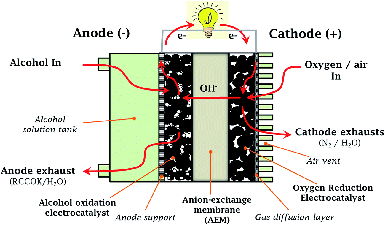 | ||
| Fig. 1 Schematic of anion-exchange membrane-based direct alcohol fuel cell (AEM-DAFC). | ||
1.1. Basic principles underlying metal nanoparticle-enhanced electrocatalytic activity
Metal nanoparticles carry out electrocatalysis more easily than large single-crystal catalysts. In his book, Roduner12 elegantly described the general principles of catalysis with nanoparticles. In a nutshell, there are several reasons why nanoparticles (clusters of atoms), often with irregular shapes, can perform better chemistry than single-crystal surfaces. The first reason is the irregularity of the particle surfaces, which provide a suitable environment for the occurrence of defects, steps, and kinks, which permit the creation of special bonding situations that are favourable for the breaking and making of bonds. The second reason is that the nanoparticles permit facile surface restructuring, unlike single crystals. It should be noted that surface restructuring constantly occurs to adapt to the adsorbate and thus the chemistry that takes place. Atoms close to the surface of small clusters are freer to move, since they have fewer neighbours to obstruct their movements compared to large single crystals.The electrode reaction, defined as the current density drawn under an overpotential, I (amperes per surface area of the electrode), is given by the following equation:13
| I (A cm−2) = j (A cm−2) s (cm2 g−1) w (g cm−2) | (1) |
The use of unit stereographic triangles (Fig. 2) to illustrate the co-ordinates of different crystal planes has been well-documented in the literature, and is not intended to be repeated here. However, a short summary here may be appropriate to remind us of the Miller indices. As shown in Fig. 2, the three low-index or basal planes (i.e., (111), (100), and (110)) are at the three vertices, while the high-index planes (i.e., (331), (311), (310), (751), etc.) are located at the sidelines (i.e., (001), (011), and (110)) and inside the triangle. The (111) and (100) planes comprise closely packed and highly coordinated surface atoms, and the (110) plane comprises step atoms, whilst the high-index planes comprise kink atoms. Surface atoms are easily differentiated from one another by the so-called coordination numbers (CNs), which are the numbers of their nearest atoms; the smaller the CN, the better the electrocatalytic performance of the nanoparticles. The CNs decrease as follows: 6 for planes in zone {001} and inside the triangle, 7 for planes in zones {011}, {110}, and (110), 8 for (100), and 9 for the (111) plane.17 Similarly, for the intrinsic triangle that coordinates the crystal surface index and the shape of metal nanocrystals (MNCs) (Fig. 2), the vertices describe the coordinates of polyhedral nanocrystals bounded by basal facets, i.e. the cube, octahedron, and rhombic dodecahedron are covered by {100}, {111}, and {110}, respectively. Inside the triangle are found the hexoctahedra bounded by 48 {hkl}, while in the sidelines of the triangle are the polyhedral MNCs, which are the tetrahexahedra (THH), trapezohedra, and trisoctahedra bounded by {hk0}, {hkk}, and {hhl} facets, respectively.17
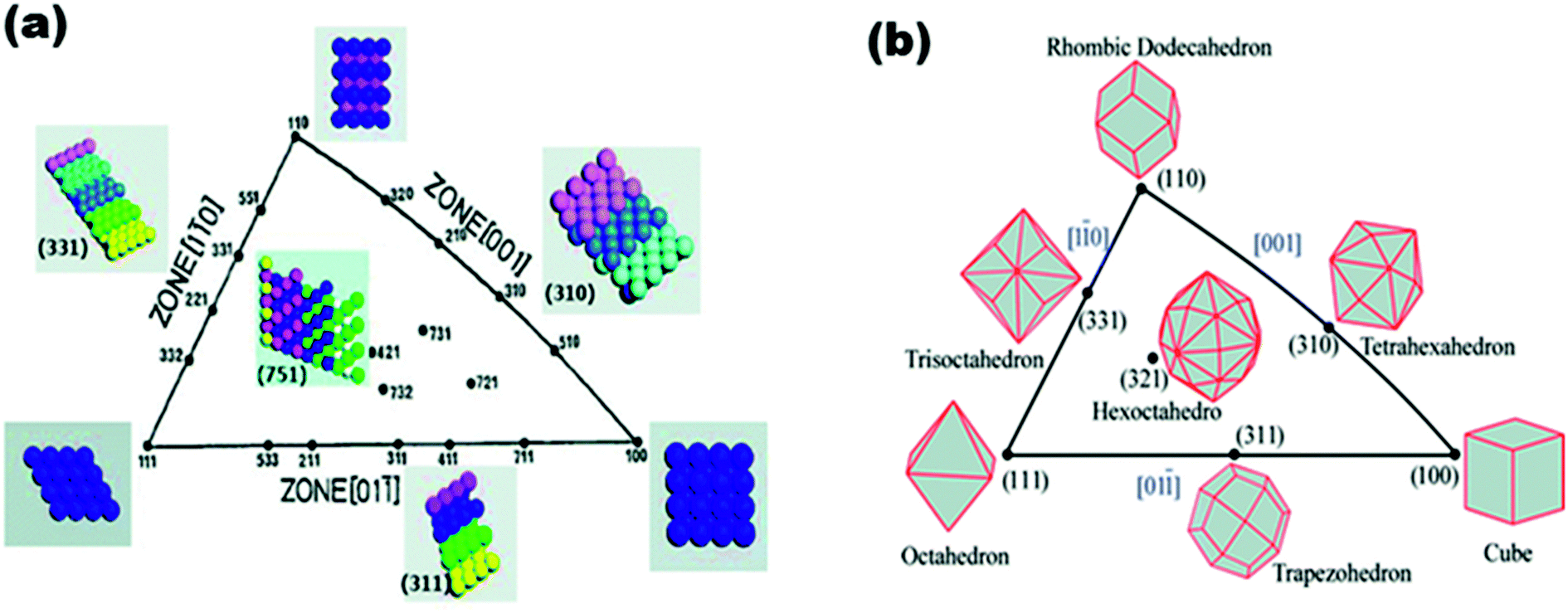 | ||
| Fig. 2 (a) Unit stereographic triangle of fcc single-crystal and models of surface atomic arrangement, (b) unit stereographic triangle of polyhedral nanocrystals bounded by different crystal planes. Figure adapted from ref. 17 with permission. | ||
| Core | Shell | |||||
|---|---|---|---|---|---|---|
| Ag | Pd | Ni | Ir | Co | Fe | |
| Ag | 0 | −0.82 | −2.29 | −3.54 | −2.15 | −5.20 |
| Pd | 0.70 | 0 | −1.09 | −1.71 | −1.29 | −3.26 |
| Ni | 0.67 | 0.46 | 0 | −0.67 | −0.20 | −2.02 |
| Ir | 1.51 | 1.34 | 0.33 | 0 | −0.04 | −1.97 |
| Co | 0.36 | 0.75 | 0.15 | 0.04 | 0 | −2.24 |
| Fe | 0.60 | 0.74 | −0.10 | 0.00 | 0.07 | 0 |
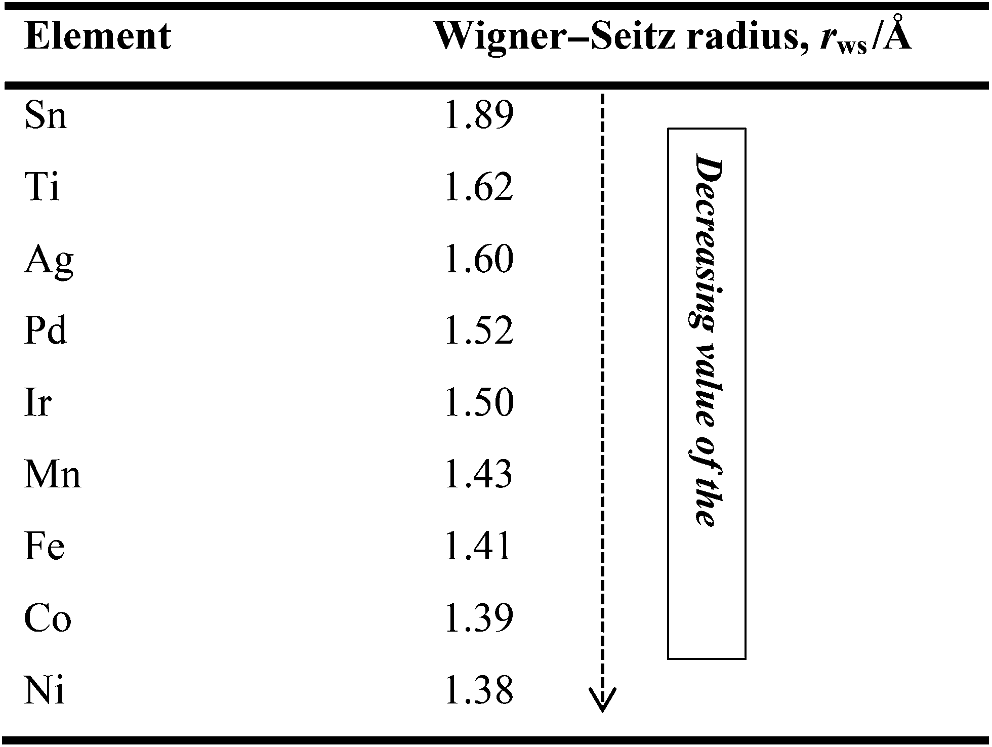
Three decades ago, Yamauchi34 formulated the rule that an element with a larger Wigner–Seitz radius (lower average electron density) in a binary alloy segregates to the surface. In other words, metallic elements with smaller atomic radii tend to occupy the core to relieve compressive strain. Thus, if one knows the WS radii or the electron densities of metals, one is then able to predict, design and make the desired nanocatalysts. For example, Table 2 compares the Wigner–Seitz radii and electron densities of some metallic elements that are useful for making alloy catalysts for AFC systems. Table 2 clearly indicates that Pd, for example, has a stronger tendency to surface-segregate in Ni, Fe, or Fe–Co alloys.
 |
This is in agreement with the recent finding by Ozoemena and co-workers,25,26,35,36 where Fe was found to occupy the ‘shell’ position in an FeCo alloy, and Pd occupied the ‘shell’ position in a high-performance sub 10 nm FeCo@Fe@Pd catalyst for alkaline direct alcohol fuel cell systems. Also, in an AgPd nanoalloy catalyst,37 Ag is predicted to surface-segregate on Pd. It is believed that the enhanced ORR activity on the AgPd alloy was a combination of two factors; modification of the electronic structure and ensemble effects. Alloying was proved to alter the electronic structures of the two metals (by shifts in the binding energy in XPS). The ensemble effect simply describes the suitable arrangement of the Ag next to the Pd surface atoms.
Catalyst-supports for fuel cells may be conveniently divided into two categories: (i) carbon-based supports and (ii) non-carbon supports. Carbon materials are the most important catalyst-support materials for fuel-cell electrocatalysts. By adopting different types of synthesis methods, different morphologies of carbons have been obtained, including core–shells, spheres, hollow spheres, nanotubes, and onion-like. The importance of carbon as a catalyst-support material stems from its unique advantages, such as easy availability, low-cost, high stability in both acidic and basic media, and ability to be burnt off easily, thus allowing for easy recovery of the precious metal catalysts if needed. Despite these important advantages, carbons are plagued by the following shortcomings, which have limited their performance as catalyst-supports: (i) severe corrosion/oxidation under normal operating conditions, leading to poor durability of the electrocatalysts as they are electrically isolated or separated from the support, and subsequent aggregation of small particles of these catalyst particles (Ostwald ripening), which can lead to the formation of an inhomogeneous structure over time.38,40,41 Indeed, the main reason for the loss of electrochemically-active surface area (ECSA) of the electrode and the consequent loss of electrocatalytic activity is related to (i) the ability of the small-sized particles to aggregate into large-sized particles via diffusion, accompanied by coalescence or the Ostwald ripening mechanism; (ii) the presence of a large amount of micropores (<1 nm), which can impede fuel supply to the surface, and present a low accessible surface area for the deposition of metal particles; (iii) low polarity and high hydrophobicity, which reduces the permeability of gases and liquids; and (iv) poor stability at temperatures higher than 373 K and lack of proton conductivity.42,43
Several types of carbons have been investigated as catalyst-supports and these include carbon blacks, carbon nanotubes (CNTs), carbon microspheres, carbon nanofibers, and graphenes. Theoretical and experimental studies have shown how the physicochemical properties of the carbons can impact on their ability to strongly adsorb catalysts and improve fuel cell performances. Two such key features of the carbons are shapes and structures. For example, Cuong et al.44 used DFT to unravel the interplay between different carbon supports (i.e., graphene sheet, a metallic single-wall carbon nanotube (SWCNT), and a series of semiconducting SWCNTs) and Pt nano-clusters, in determining the stability and electronic properties of Pt nanoclusters (Fig. 3). It was established that the Pt clusters were best stabilized by adsorption on carbon nanotubes, rather than on graphene supports, with the adsorption energy of Pt clusters on SWCNTs (4.0 eV) being much higher than that of graphene (2.21 eV).
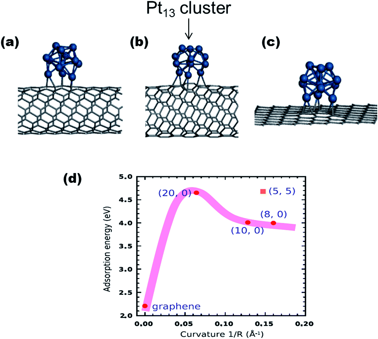 | ||
| Fig. 3 The geometric structures of Pt13 clusters adsorbed on carbon supports: (a) metallic (5, 5) SWNT, (b) semiconducting (10, 0) SWNT, and (c) (8 × 8) graphene surface. (d) describes the dependence of the curvature of the carbon supports on the adsorption energy of Pt13 clusters on the SWNTs and graphene sheet. Figure adapted from ref. 44 with permission. | ||
The enhanced stability of the Pt cluster on SWCNTs was associated with the geometry of the SWCNTs; “due to the curvature-induced pyramidalization and misalignment of p-orbitals of carbon atoms in SWCNT, carbon atoms on the outside wall of the SWCNT have more sp3 nature than those on a flat graphene sheet”.44 This finding could well explain the generally high-performing ability of CNT-supported catalysts compared to catalysts adsorbed on graphite carbons. Considering that the metal–carbon bonding arises from the hybridization between d-states of the metal atoms and p-states of adjacent carbon atoms, this means that the high curvature of the CNTs is able to promote the overlap between p and d wave functions, thus increasing the adsorption energy of metal on CNTs.
Another key feature of a carbon surface that influences its ability to interact with metal catalysts is surface functional groups. The two main functionalities are oxygen and nitrogen (Fig. 4). The commonly observed oxygen functionalities are carboxyl (–COOH), hydroxyl (–OH), and carbonyl (–C![[double bond, length as m-dash]](https://www.rsc.org/images/entities/char_e001.gif) O) groups. Although a number of dopants are being reported on a constant basis, nitrogen-doping has emerged as an efficient strategy for tailoring the properties of carbons and tuning the physicochemical properties of carbon materials for a plethora of applications.45 For the nitrogen-doped carbons (Fig. 4), the three most commonly observed are the pyridinic, pyrrolic, and graphitic nitrogen groups. The main goal of surface-functionalization of carbon materials is to improve their hydrophilicity (e.g., treatment with acids and bases) or hydrophobicity (e.g., treatment with organic compounds such as benzene), with a view to enhancing their dispersibility in solvents and permitting anchorage of the metal catalysts. CNTs are attractive supports for electrocatalysts due to their excellent mechanical strength, high-surface area, high conductivity and, of course, their inherent geometry, which allows for the high binding energy with metal catalysts, as described above.
O) groups. Although a number of dopants are being reported on a constant basis, nitrogen-doping has emerged as an efficient strategy for tailoring the properties of carbons and tuning the physicochemical properties of carbon materials for a plethora of applications.45 For the nitrogen-doped carbons (Fig. 4), the three most commonly observed are the pyridinic, pyrrolic, and graphitic nitrogen groups. The main goal of surface-functionalization of carbon materials is to improve their hydrophilicity (e.g., treatment with acids and bases) or hydrophobicity (e.g., treatment with organic compounds such as benzene), with a view to enhancing their dispersibility in solvents and permitting anchorage of the metal catalysts. CNTs are attractive supports for electrocatalysts due to their excellent mechanical strength, high-surface area, high conductivity and, of course, their inherent geometry, which allows for the high binding energy with metal catalysts, as described above.
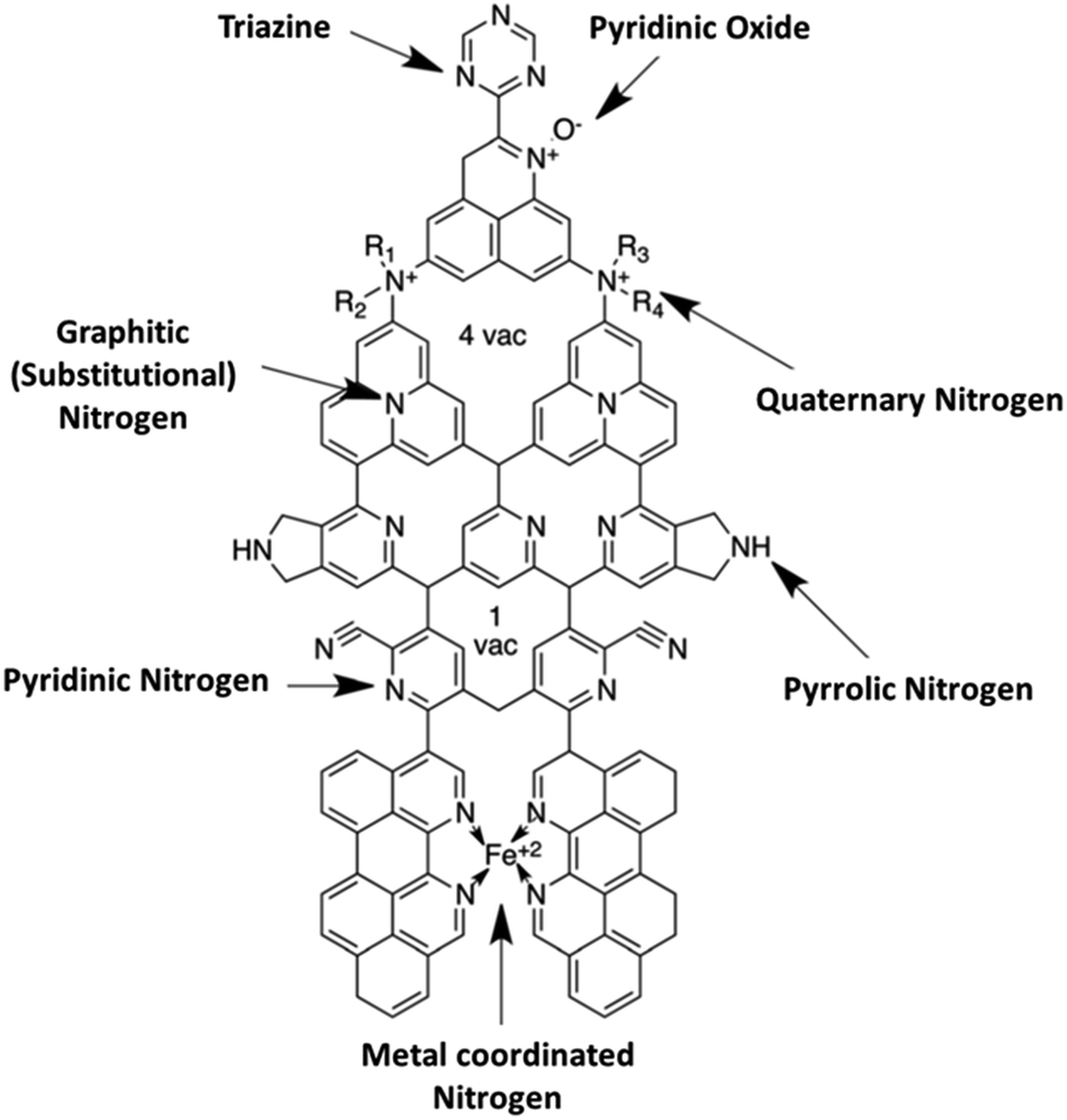 | ||
| Fig. 4 Structure depicting nitrogen functionalities in nitrogen-doped carbon materials, the most commonly observed groups being the pyridinic, pyrrolic and graphitic. Figure adapted from ref. 45 with permission. | ||
The surface-functional groups provide the binding sites for the growth of the metal catalyst ions. The conventional method for surface-functionalisation of CNTs, and indeed any carbon materials, involves treatment with acids or bases, a simple chemical treatment that permits the introduction of surface groups, such as carboxyl, hydroxyl, phenolic, sulfonyl, or sulfite groups on the carbon surfaces. About a decade ago, Kim and Park46 investigated the effects of the chemical treatment of carbon supports on the electrochemistry of platinum catalysts. The following carbon supports were studied; virgin carbon blacks (CBs), neutral-treated carbon blacks (NCBs obtained by treating CBs with 0.2 M benzene), base-treated carbon blacks (BCBs, obtained by treating CBs with 0.2 M KOH), and acid-treated carbon blacks (ACBs, obtained by treating CBs with 0.2 M H3PO4). The authors showed that the size and the catalyst-loading were strongly dependent on the surface characteristics of the carbon blacks: BCB-supported Pt yielded the smallest particle size (2.65 nm) and the highest loading (97%) compared to the other carbons investigated. The electroactivity of the catalyst was enhanced with BCBs and NCBs, but deteriorated with ACBs.
Another interesting method of improving the surface properties of nanocarbon materials, including CNTs, is sulfonation,47–49 which was first introduced by Hara et al. in 2004.50 In a recent review by Kang et al.,47 the authors discussed a number of synthesis methods for sulfonated nanocarbons, including their applications. To improve the sulfonation process, Ozoemena and co-workers51 first functionalised pristine CNTs to increase the concentration of the oxo-groups (mainly the –COOH) by a three-step acid-treatment process: (i) refluxing in 2.6 M HNO3 for 24 h; (ii) sonicating in an H2SO4/HNO3 mixture (3![[thin space (1/6-em)]](https://www.rsc.org/images/entities/char_2009.gif) :1 ratio) for 24 h; and (iii) stirring in an H2SO4/H2O2 mixture (4:1 ratio) at 70 °C. The acid-functionalised CNTs (MWCNT-COOH) were then sulfonated using a mixture of H2SO4 and acetic anhydride at 70 °C for 2 h, using the procedure reported by Sun et al.48,49 The catalysts were supported on the sulfonated-CNTs (MWCNT-SO3H) using rapid microwave irradiation, as shown in Fig. 5.
:1 ratio) for 24 h; and (iii) stirring in an H2SO4/H2O2 mixture (4:1 ratio) at 70 °C. The acid-functionalised CNTs (MWCNT-COOH) were then sulfonated using a mixture of H2SO4 and acetic anhydride at 70 °C for 2 h, using the procedure reported by Sun et al.48,49 The catalysts were supported on the sulfonated-CNTs (MWCNT-SO3H) using rapid microwave irradiation, as shown in Fig. 5.
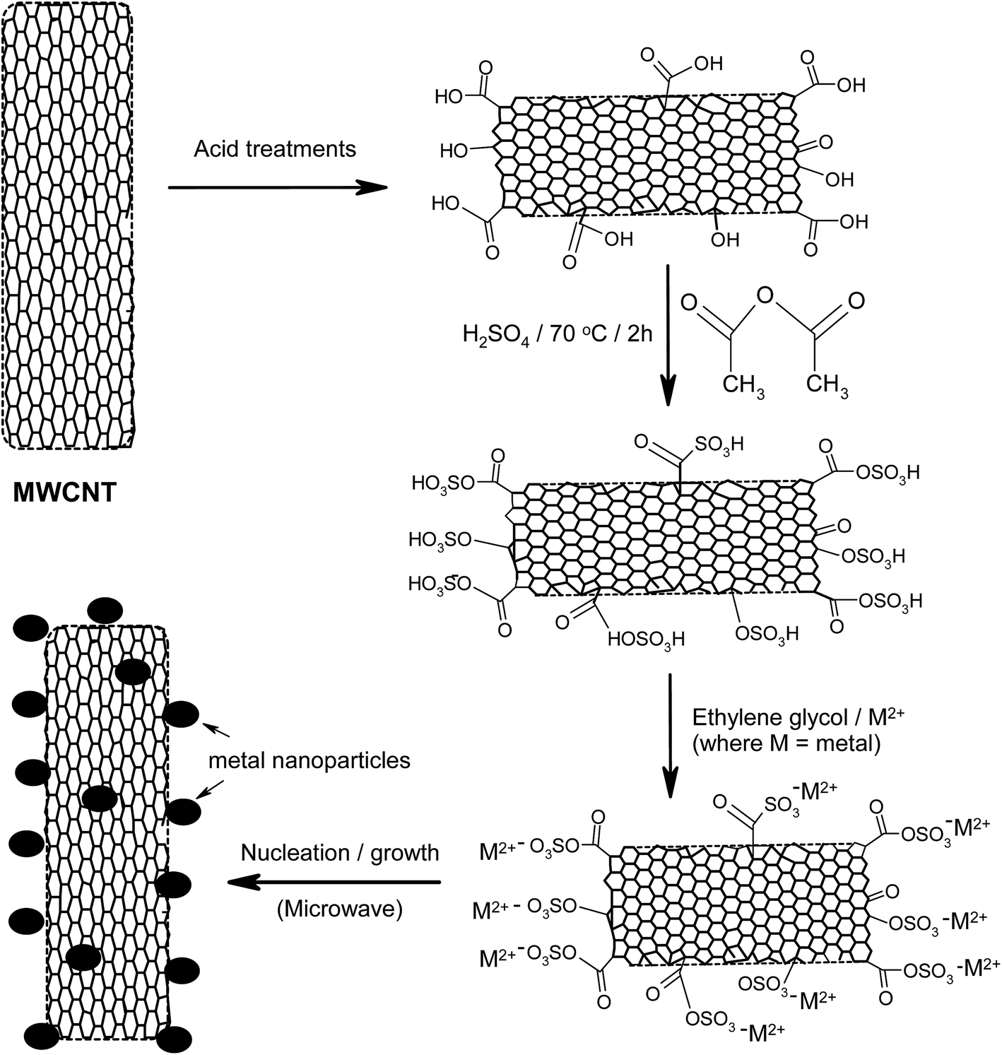 | ||
| Fig. 5 Schematic of the sulfonation process for carbon nanotubes using microwave-assisted synthesis. Figure modified from ref. 51 with permission. | ||
Sun et al.48,49 showed that a Pd catalyst supported on sulfonated MWCNT (Pd/MWCNT-SO3H) had an enhanced catalytic activity for methanol oxidation48 and the ethylene glycol oxidation reaction.49 The MWCNT-SO3H allowed for uniform dispersion of smaller-sized Pd nanoparticles (∼4.5 nm) compared to MWCNT supports that were not sulphonated. The uniform dispersion was associated with the specific electrostatic interactions between negatively charged MWCNTs and positively charged Pd (Pd2+). Ramulifho et al.51 adopted similar functionalization of MWCNTs for the synthesis of bimetallic Pd-based catalysts using a microwave-assisted method, rather than the conventional NaBH4 reduction method used by Sun et al.48,49 The authors showed that the catalytic properties of the PdSn catalyst followed this trend: PdSn/MWCNT-SO3H > PdSn/MWCNT-COOH > PdSn/C.
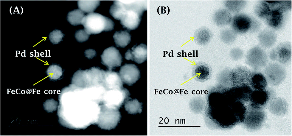
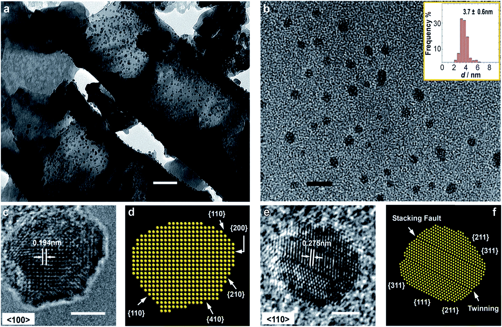
To understand the effect of sulfonation on MWCNT supports, Ozoemena and co-workers recently investigated the catalytic properties of an FeCo@Fe@Pd nanocatalyst supported on MWCNT-COOH and MWCNT-SO3H. The core–core–shell Pd-based nanocatalysts (FeCo@Fe@Pd) were obtained by what has been termed “microwave-induced top-down nanostructuring and decoration (MITNAD)”,25 a process whereby a large-sized precursor core–shell alloy (FeCo@Fe, ≥0.5 μm) was reduced to a nano-sized structure and decorated with a Pd-shell (FeCo@Fe@Pd, ≤10 nm) by fast microwave irradiation (Fig. 6). The authors clearly proved that surface functionalities (mainly –COOH and –SO3H) on the MWCNT support played a crucial role in the physico-chemistry of the FeCo@Fe@Pd catalyst toward the oxidation of polyhydric alcohols, ethylene glycol, and glycerol. The FeCo@Fe@Pd/MWCNT-COOH (Fig. 6A and B and 7) gave smaller-sized particles (ca. 7.4 nm), more uniform dispersion or loading of the catalyst on the support, a higher electrochemically active surface area (ECSA, ca. 75 m2 g−1) and an enhanced electrocatalytic activity compared to the FeCo@Fe@Pd/MWCNT-SO3H (Fig. 6C and D), with ca. 11 nm particle size and an ECSA of ca. 42 m2 g−1. This finding is in good agreement with the report by Kim and Park,46 as already discussed above, where carbon black treated with acid showed a poor catalyst loading compared to the base-treated or neutral carbon blacks. It is possible that the MWCNT-COOH support (a weak acid) might have led to complete reduction of the Pd2+, thus allowing a more uniform dispersion and higher loading of catalysts than the MWCNT-SO3H support (strong acid). Simply stated, the high catalytic performance of FeCo@Fe@Pd/MWCNT-COOH may be related to the improved electronic properties of the catalyst, coupled with the high affinity of its –COOH surface with the catalyst. It should be noted, however, that this finding is in contradiction to previous findings,48,49,51 and this may be related to several factors, including the nature of the pristine CNTs used (i.e., the amount of –COOH available), the nature of the alloys (e.g., the arrangement of the Sn on Pd), and the synthesis method used (fast microwave-assisted acid-functionalization vs. a lengthy hydrothermal reaction).
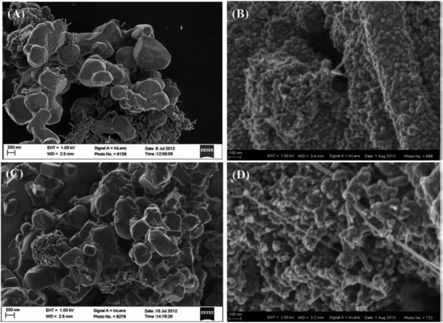 | ||
| Fig. 6 FESEM images describing the importance of the “microwave-induced top-down nanostructuring and decoration” (MITNAD) process: (A) FeCo@Fe/MWCNT-COOH (≥0.5 μm), (B) FeCo@Fe@Pd/MWCNT-COOH (≤10 nm), (C) FeCo@Fe/MWCNT-SO3H (≥0.5 μm), and (D) FeCo@Fe@Pd/MWCNT-SO3H (≤10 nm). Figure adapted from ref. 25 with permission. | ||
 | ||
| Fig. 7 (A) High-angle annular dark-field (HAADF)- and (B) bright-field (BF)-STEM images simultaneously acquired for FeCo@Fe@Pd/MWCNT-COOH. Figure adapted and modified from ref. 25 with permission. | ||
Despite the advantages of chemical oxidation of carbon supports to introduce surface-functional groups, it should be noted that the oxidised sites of the carbon supports may accelerate the degradation process of the support material, thereby inducing significant aggregation of the catalyst nanoparticles. One of the strategies to avoid the occurrence of these oxidation problems is to wrap the carbon support with polymeric materials that contain appropriate functional groups for the binding of the metal catalyst. For example, Fujigaya and co-workers elegantly wrapped CNTs with polymeric materials that contain nitrogen atoms (i.e., pyridine-doped polybenzimidazole52) and poly[2,29-(2,6-pyridine)-5,59-bibenzimidazole53], sulfonic acid (i.e., sulfonated polysulfone and sulfonated polyimide54) and phosphonic acid groups (i.e., poly(vinyl phosphonic acid)-doped polybenzimidazole55). The catalysts displayed excellent stability with a durability 10 times higher than that of commercial carbon black/Pt.
To mitigate the problems of carbon-based supports in fuel cells, especially the issue of corrosion, several non-carbon supports for fuel cells are being developed without sacrificing the desirable properties of carbon, such as high surface area and high electrical conductivity. The non-carbon materials include the following: (i) conducting polymers, such as polypyrrole (PPY) and polyaniline (PANI); (ii) metal oxides and hydroxides, such as ZrO2, CeO2, TiO2, MnO2, and Al2O3; (iii) transition metal carbides, such as tungsten monocarbide (WC), and (iv) transition metal nitrides, including binary nitrides (e.g., CrN, TiN) and ternary nitride (e.g., Ti0.5Nb0.5N) complexes. For more information on these non-carbon supports, the reader is referred to the recent book chapter by Ejikeme et al.56
1.2. Synthesis of nanoelectrocatalysts for application in AEM-ADAFCs
As already explained in the preceding section, the catalytic activities of nanostructured electrocatalysts strongly depend upon their elemental composition, size or surface area, shape with the preferred surface structure (exposed surface planes), and the extent of interaction with supports. For an anodic reaction (i.e., the alcohol oxidation reaction), Pd-based metal catalysts are used, while for a cathodic reaction (i.e., the oxygen reduction reaction), non-platinum group metal (non-PGM) catalysts or Pt-free catalysts are used. The catalysts (anodic and cathodic) are synthesized using similar methods. The key synthesis methods can be summarised as chemical reduction, galvanic replacement, seed-mediated growth, and electrochemical deposition. Each of these methods can be used alone or combined with another method to prepare a catalyst.Surfactants, such as PVP and CTAB, have the ability to tune the physico-chemistry of the catalysts and improve their catalytic performance. For example, Xia and coworkers60 demonstrated the synthesis of Pt–Pd alloy nanocrystals with well-defined shapes and twinned structures by simply heating an aqueous solution of Na2PdCl4, K2PtCl4, and PVP at 80 °C for 18 h. It was found that this lengthy or slow-reduction synthesis process with a weak reductant was responsible for the formation of the twinned structure. The PVP-mediated slow reduction rate (owing to the hydroxyl terminal group of the PVP) was able to retain the particles at small sizes for a long period of time before nucleation could start. The slow process allows for easy coalescence of small particles into larger particles, thereby reducing the surface-to-volume ratio, thus leading to the formation of twinned structures. When the process was repeated with ethylene glycol, which is a relatively high-rate reductant, a single-crystal structure of Pt–Pd nanocrystals with a truncated, octahedral shape was obtained.
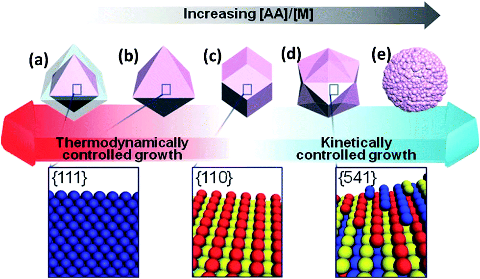
Lee et al.61 obtained Au–Pd nanocrystals (NCs) (Fig. 8) enclosed exclusively by high-index facets {541}, by one-pot aqueous synthesis involving simultaneous reduction of Au and Pd precursors. The nanocrystals were made possible by manipulating the growth kinetics, by controlling the relative amounts of reductant, ascorbic acid (AA), to the metal (M) precursors. It is interesting to observe that AA plays a critical role in the morphology of the NCs. The co-reduction of Au and Pd precursor salts with CTAB in the absence of AA produced Au@Pd core–shell NCs with an octahedral shape (ca. 48 h at 90 °C). On the contrary, however, the co-reduction of the metal precursor salts in the presence of AA at an [AA]/[M] ratio of 0.75 (where [M] is the metal precursor concentration) (2 h at room temperature), yielded Au–Pd alloy NCs with {111}-faceted octahedral morphology. When the [AA]/[M] ratio was 1, rhombic dodecahedral (RD) Au–Pd alloy NCs exclusively bound by {110} facets were obtained. Increasing the [AA]/[M] ratio to 4 yielded hexoctahedral (HOH) Au–Pd alloy NCs predominantly bound by high-index {541} facets. The changes in the morphology of the NCs following changes in the [AA]/[M] ratio are elegantly described by the authors (Fig. 8). As should be expected, the HOH Au–Pd alloy NCs showed a higher catalytic performance toward the electro-oxidation of ethanol in alkaline media than equivalent RD Au–Pd alloy NCs bound by low-index facets (Fig. 9c and d).
 | ||
| Fig. 8 Schematic of the correlation between the morphology of Au–Pd NCs and the NC growth kinetics; (a) core–shell octahedron, (b) octahedron, (c) rhombic dodecahedron (RD), (d) hexoctahedron (HOH), and (e) flower-like structure. Corresponding 3D lattice models for the surface facets of NCs are shown below the scheme. Figure adapted from ref. 61 with permission. | ||
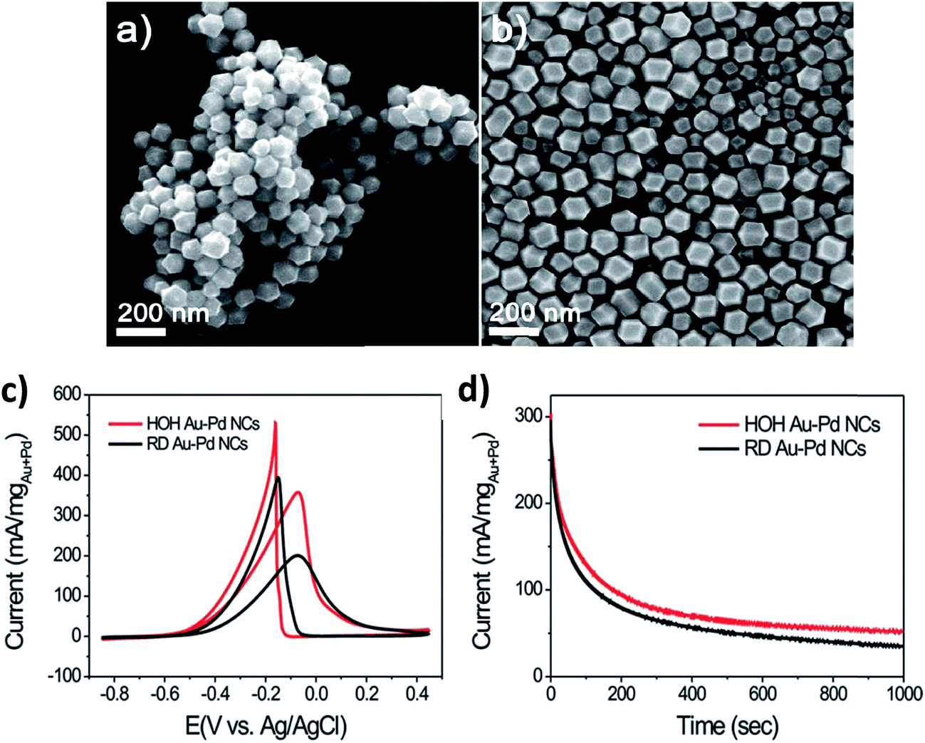 | ||
| Fig. 9 SEM images of (a) HOH and (b) RD Au–Pd alloy NCs, (c) cyclic voltammograms of GCE-modified HOH and RD Au–Pd alloy NCs obtained in 0.1 M KOH + 0.5 M ethanol at a scan rate of 50 mV s−1, and (d) chronoamperograms of HOH and RD Au–Pd alloy NCs at −0.1 V vs. Ag/AgCl. Figure adapted from ref. 61 with permission. | ||
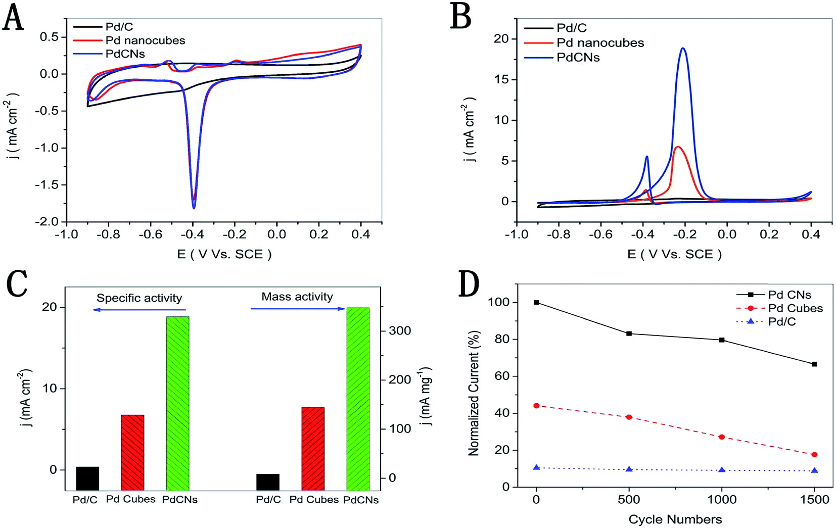 | ||
| Fig. 10 Cyclic voltammograms of the PdCNs, Pd nanocubes, and commercial Pd/C, which are recorded at room temperature with a scan rate of 50 mV s−1 in (A) 1 M KOH solution; (B) 1 M KOH containing 1 M CH3OH; (C) the mass and specific activities (−0.2 V vs. SCE); (D) normalized current of 1500 cycles. Figure adapted from ref. 74 with permission. | ||
In 2007, Sun and co-workers76,77 first reported the use of a square-wave potential treatment (SWPT) process for the synthesis of Pt nanocrystals covered with high-index facets. This unique process was able to generate high-index faceted Pt nano-crystals supported on carbon black with a small size (2–10 nm), comparable to that of the standard commercial Pt/C catalysts.78 Since the introduction of this technique, other workers have also used the technique to transform the shapes of some nanocrystals. For example, Zhou et al. used the technique to transform Pt nanocubes to tetrahexahedra with an average size of ∼10 nm.79 The technique was able to transform the surface structure from low-index facets {100} to high-index facets {310}, thereby significantly improving the electrocatalysis of the ethanol oxidation reaction. In 2010, the same authors80 slightly modified the technique for the synthesis of palladium nanocrystals with high-index facets, with an average particle diameter of 61 nm. In 2015, Lin et al. adopted the method to synthesize Bi-decorated Pd tetrahexahedral nanocrystals for the ethanol oxidation reaction.81
In 2012, Vizza and co-workers82 reported a modified SWPT named electrochemical milling and faceting (ECMF). In this method, the authors first electrodeposited large Pd nanoparticles (35 nm) with low-index facets supported on TiO2 nanotube arrays (TNTAs), and then applied a two-step SWPT (see Fig. 11) involving “heavy” and “mild” oxidation–reduction steps that finally yielded Pd nanocrystals of a small mean particle size of 7 nm (milling) and high-index facets (faceting) (Fig. 12). The obtained TNTA-modified Pd nanocrystals exhibited improved electrocatalysis towards the EOR (in terms of current density, mass-specific activity, and onset potential) compared to the as-deposited TNTA–Pd.
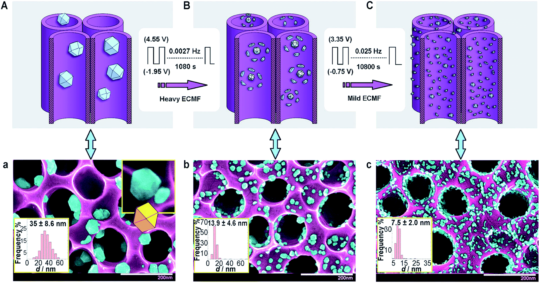 | ||
| Fig. 11 (A) TNTAs with as-deposited Pd and (a) the corresponding SEM image. (B) TNTAs with Pd after heavy ECMF and (b) the corresponding SEM image. (C) TNTAs with Pd after heavy and mild ECFM and (c) the corresponding SEM image. False coloring of the SEM images shows Pd NPs (light blue) and the TNTA support (violet). The white scale bars in (a–c) are 200 nm. Figure adapted from ref. 82 with permission. | ||
 | ||
| Fig. 12 (a) TEM image of the Pd-loaded TNTA electrode after heavy and mild ECMF (scale bar = 50 nm). (b) Pd nanoparticles found in the electrolyte after heavy and mild ECMF (scale bar = 35 nm). (c) HRTEM image (scale bar = 2 nm) and (d) atomic models with face assignment of the TNTA-supported Pd nanoparticle along the {100} direction. (e) HRTEM image (scale bar = 2 nm) and (f) face assignment of the TNTA-supported Pd nanoparticles along the {110} direction. Figure adapted from ref. 82 with permission. | ||
2. Nanocatalysts for alcohol oxidation reaction (AOR) in alkaline media
2.1. Introduction: an overview of the general reaction mechanism
The various advantages that characterize the use of alkaline media in the efficient electrocatalytic oxidation of alcohols have been elegantly reviewed by Bianchini and Shen.3 Some of the advantages include: (i) the possibility to deploy low-cost non-precious metal catalysts; (ii) improved kinetics at low overpotentials; (iii) reduced ability of the reacting alcohol to crossover from its anodic compartment to the cathodic side; (iv) improved water management of the cell; water is generated at the anodic compartment where water already exists, while water is removed from the cathodic compartment via electro-osmotic drag, thereby preventing the possibility of water-flooding; (v) minimum corrosion risks for the electrode materials; and (vi) minimum risks of the adsorption of the spectator ions onto the MEAs. In addition, catalyst poisoning is very weak in alkaline media.5,6The two most investigated monohydric or primary alcohols are methanol and ethanol, while the polyhydric alcohols are glycerol and ethylene glycol. The popularity of these alcohols in ADAFCs stems from their unique advantages of high gravimetric and volumetric energy densities (Table 3). The volumetric energy density of each of the alcohols (ca. 5.0–7.5 kW h L−1) is slightly lower than that of gasoline (ca. 9.5 kW h L−1) and anthracite coal (ca. 10.2 kW h L−1), but much higher than that of hydrogen (1.6 kW h L−1) or lithium-ion batteries, or electrochemical capacitors (<0.02 kW h L−1). Also, one often finds that KOH is the most important electrolyte for the AFC and ADAFC systems, rather than its NaOH counterpart, and this should perhaps not be surprising as KOH is less caustic than NaOH, which means that the degradation of some of the components of a fuel cell, such as the gaskets, will be milder than with NaOH. In addition, KOH is ionically more conductive than NaOH, which means that the ohmic overpotential losses are higher with NaOH than with KOH.
| Fuel | Density at 20 °C/g cm−3 | Specific energy density/kW h kg−1 | Volumetric energy density/kW h L−1 | n |
|---|---|---|---|---|
| Methanol | 0.787 | 6.36 | 4.99 | 6e− |
| Ethanol | 0.785 | 8.32 | 6.52 | 12e− |
| Ethylene glycol | 1.113 | 5.30 | 5.87 | 10e− |
| Glycerol | 1.261 | 5.00 | 6.26 | 14e− |
| Propan-1-ol | 0.800 | 9.41 | 7.53 | 18e− |
| Propan-2-ol (isopropanol) | 0.781 | 9.35 | 7.30 | 18e− |
| Gasoline | 0.716 | 13.24 | 9.48 | — |
| Hydrogen (at 700 bar) | 34.72 | 1.57 | 2e− | |
| Coal (anthracite) | 1.350 | 7.56 | 10.21 | — |
| Coal (lignite) | 0.801 | 4.20 | 3.36 | — |
| Lithium-ion battery (re-chargeable) | — | 0.100–0.245 | 0.252–0.736 | — |
| Supercapacitor (EDLC) | — | 0.003–0.010 | 0.014–0.017 | — |
| Supercapacitor (pseudocapacitor) | — | 0.009 | 0.013 | — |
With the exception of methanol, which requires 6 electrons for complete oxidation, the oxidation of higher alcohols is more difficult, as they require between 10 and 18 electrons for complete oxidation. Presently, much effort is being devoted to improving their electro-oxidation performance by utilising Pd-based bimetallic and ternary catalysts, and understanding the underlying mechanisms.83–85 From the “bi-functional theory”,86 the electro-oxidation of primary alcohols (e.g., methanol and ethanol) to CO2 and R–COOH (or CO32− and R–COO− in alkaline medium) requires the activation of H2O under OH adsorbed species (OHads) at the catalyst's surface, to provide the extra oxygen atom and to complete the AOR, in accordance with eqn (2)–(6), occurring in alkaline electrolyte:
| Pd + RCH2OH → Pd–(RCH2OH)ads | (2) |
| Pd–(RCH2OH)ads + 3OH− → Pd–(RCO)ads + 3H2O + 3e− | (3) |
| Pd–OH− → Pd–OHads− + e− | (4) |
| Pd–(RCO)ads + Pd–OHads− → Pd–(RCOOH) + Pd rds | (5) |
| RCOOH + OH− → RCOO− + H2O | (6) |
Eqn (2) and (3) relate to the fast dissociative adsorption of alcohol on the catalyst surface. Eqn (5) is the rate-determining step (rds), which means that the AOR strongly depends on the coverage of the adsorbed acyl and hydoxyl species, RCOads and OHads, on the surface of the nanocatalyst, generally leading to the formation of the acetate. Nano-sizing of the catalysts improves the rate of hydroxyl adsorption on the catalyst surface.87
Some researchers have shown that the catalytic performance of Pd nanocatalysts for the AOR in alkaline media (in respect of activity and stability) can be greatly enhanced by incorporating catalysts with metal oxides (such as NiO, CeO2, Co3O4, and Mn3O4).88–90 Indeed, the metal oxides play the same role as Ru in the PtRu/C catalysts in the bi-functional mechanism by increasing the concentration of OHads species on the surface of the electrocatalyst for C–C bond cleavage and formation of the final oxidation products. Similarly, the enhancing catalytic role of metal oxides has been attributed to the so-called spillover of the primary oxide (M–OH).91
It should be pointed out that the mechanism of the AOR in alkaline media is intriguing as it is somewhat controversial and unclear. It is undeniable, though, that the reaction steps are mediated by both the solution/electrolyte conditions and metal catalyst. Two recent studies can help explain this point. In 2011, Koper and co-workers92 reported that the AOR in alkaline media on a gold electrode follows the Hammett-type correlation (the lower the pKa of the alcohol, the higher its reactivity) as exemplified by this trend:
| Glycerol (pKa = 14.15) > ethylene glycol (pKa = 14.77) > ethanol (pKa = 15.9) > isopropanol (pKa = 17.1) |
According to the authors, this trend is due to the solution hydroxide, which leads to the initial base-catalysed deprotonation reaction of the alcohol as the rate-determining step (rds), followed by the fast gold-catalysed deprotonation step. They concluded that the “base catalysis is the main driver behind the high oxidation activity of many organic fuels on fuel cell anodes in alkaline media, and not the catalyst interaction with hydroxide”.92
In 2015, interestingly, Coutanceau and co-workers93 studied the same alcohols in alkaline media using Pd–Sn catalysts and obtained exactly the opposite trend:
| Isopropanol (pKa = 17.1) > ethanol (pKa = 15.9) > ethylene glycol (pKa = 14.77) > glycerol (pKa = 14.15) |
According to the authors, the rds is not the initial base catalysis, as in the case of the gold electrode, but the ability of the catalyst surface to dissociatively adsorb the reacting alcohol or quickly desorb the reaction products of the AOR. They attributed the higher reactivity of the isopropanol to the ease by which the acetone desorption (i.e., the rds of isopropanol oxidation on the Pd–Ni catalyst94) occurs at the catalyst surface, compared to the more difficult dihydroxyacetone desorption (i.e., possible rds of glycerol oxidation) from the catalyst surface.
2.2. Electro-oxidation of monohydric alcohols
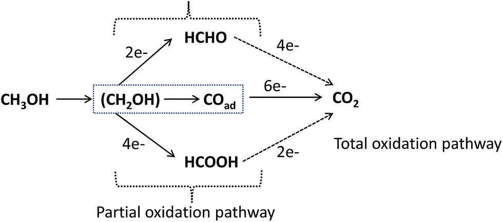 | ||
| Fig. 13 Schematic of the parallel pathways for the electrocatalytic oxidation of methanol. | ||
The main disadvantage of methanol is its toxicity. Compared to other known metals, Pt gives the best catalytic activity toward the MOR, both in acidic and alkaline solutions. The activity of Pd toward the MOR in alkaline solution can be greatly enhanced by incorporating another metal in the alloyed form (such as Pd–Ni/C)96,97 or in the oxide form (such as Pd–NiO/C),98,99 thus explaining the reason why most reports today on the MOR in alkaline media deploy Pd-based bimetallic nanocatalysts. The promoting effect of Ni or its oxide form should perhaps not be surprising, as Ni has long been known to oxidize primary alcohols to acids,100 as shown in eqn (7) and (8). When Ni is placed in alkaline solution, it is covered with a layer of nickel hydroxide; the surface transformation and subsequent electro-oxidation of the alcohol to organic acids are normally written as follows:100
| Ni(OH)2 → NiOOH + H+ + e− | (7) |
| RCH2OH + NiOOH → RCOOH + Ni(OH)2 | (8) |
The NiO is said to promote the anti-poisoning properties of the PdNiO/C catalyst. Indeed, the last five years have seen an increase in research activities aimed at improving the catalytic activity of nanostructured Pd-based bimetallic catalysts for the MOR in alkaline media.
Recently, some non-precious metal oxides (notably, oxides of tin, cobalt, and nickel) have been reported as viable nanocatalysts for the MOR. Shi's group101 showed that nanocomposites of tin oxide nanocrystals (∼3 nm) homogenously decorated on the surface of mesoporous zeolite (i.e., SnO2/m-ZSM-5) exhibited high and stable electrocatalytic properties for the MOR, comparable to Pt/C. According to the authors, the enhanced performance was related to the excellent tolerance of CO poisoning, stemming from the synergistic interaction between SnO2 and m-ZSM-5. In 2016, Asghari and co-workers102 showed that hierarchical nanostructured tin-oxide-decorated polypyrrole on nanoporous copper (porous Cu/PPy/SnOx) showed enhanced MOR catalysis compared to its smooth Cu/PPy/SnOx and porous Cu/PPy counterparts. The improved performance was attributed to factors such as the ability of the SnOx to bring about the adsorption of MOR intermediates and oxidation of the products, such as CO, permitting the dehydrogenation of the alcohols, including the increased microscopic surface area of the electrodes. Wu et al.103 reported that a Co3O4/NiO core–shell nanowire array (with mesoporous nanowire core and branched nanoflake shell), obtained by combined hydrothermal and electrodeposition methods, showed excellent electrocatalysis toward the MOR compared to its single Co3O4 nanowire array. The enhanced performance was attributed to the synergy between the core–shell architecture, which allowed for fast kinetics and a lower overpotential. An interesting finding on the electrocatalytic properties of NiOx and MnOx was reported by Saleh's group.104 According to the authors, electrodeposited NiOx and MnOx nanocomposites on glassy carbon provided an excellent catalyst platform for the MOR, but to achieve the desired catalytic effects, NiOx must be sitting on the MnOx surface, and not the other way around (i.e., GC/MnOx/NiOx). The enhanced activity was ascribed to the enhanced adsorbability of MeOH on the MnOx. Indeed, these reports are highly promising for the development of precious metal-free catalyst design for alcohol oxidation.
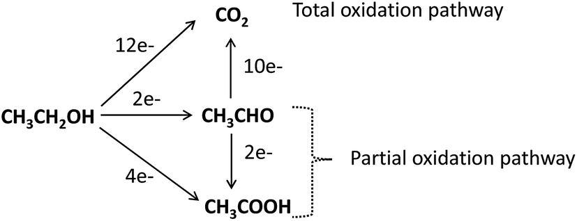 | ||
| Fig. 14 Schematic of the parallel pathways for the electrocatalytic oxidation of ethanol. | ||
Unlike the MOR, the EOR in alkaline solution is more feasible with a Pd than a Pt catalyst. To realize the bifunctional mechanism, the majority of the EOR studies in alkaline electrolyte in the last five years have focused on Pd-based bimetallic catalysts, such as Pd–Ag,106–109 Pd–Ni,51,110–113 Pd–Sn,114–116 Pd–Pb,117 Pb–Tb,118 Pd–Bi,119 Pd–In2O3,120 Pd–NiO,90 and Pd–CeO2,90 as well as ternary catalysts, such as Pd–Ir–Ni,121 Pd–Ru–Sn,114 FeCo@Fe@Pd,36 and Pd–Fe2CoOx.122
The underlying mechanisms of the Pd-catalyzed EOR in alkaline media, established from in situ spectroscopic techniques, are intricately linked to factors such as the pH electrolyte, electrode potential, water, and adsorbed acyl and hydroxyl species. Recently, using in situ FTIR spectroelectrochemistry, Fang et al.123 proved that breaking of the C–C bond of ethanol at the Pd electrode is dependent on the pH of the electrolyte; total C–C bond breaking occurs only at pH ≤ 13, while at pH 14, partial oxidation occurs, with acetate being the only oxidation product of the EOR, indicating that the faradic efficiency of the EOR with Pd is lowered at an elevated alkaline pH.
The effect of the applied electrode potential on the cleavage of C–C bonds in the EOR was recently established by Yang et al.,124 from in situ attenuated total reflection surface enhanced infrared adsorption spectroscopy (ATR-SEIRAS). From their findings, the authors proposed a 2-way mechanistic pathway (Fig. 15). At the open-circuit potential (OCP) or lower potential (<−0.1 V) an adsorbed acyl species (CH3COads) is formed, which is further electro-oxidized through a C2 pathway to form CH3COO− (at high anode potentials, >−0.4 V) or a C1 pathway to COad and CHx and eventually to CO2 (at low potentials).
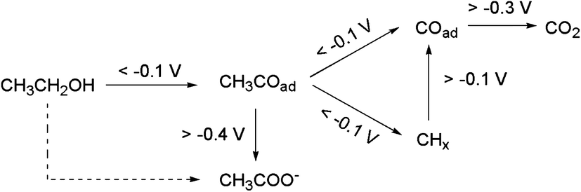 | ||
| Fig. 15 Reaction pathways for interfacial CH3CH2OH oxidation on a Pd electrode in alkaline media (the dashed-line arrow is not accompanied by any direct spectral evidence). Figure adapted from ref. 124 with permission. | ||
A recent study on ab initio molecular dynamics simulations by Sheng et al.125 demonstrated the importance of water and OHads on the EOR mechanism on a Pd electrode in alkaline media. As depicted in Fig. 16, ethanol adsorbed in the IHP on Pd(111) overcomes a barrier to produce acetaldehyde (CH3CHO) first. However, because of the weak adsorption of CH3CHO, the formed CH3CHO immediately desorbs to the electrolyte solution, in which a sufficient amount of geminal diol (CH3CH(OH)2) is produced. The CH3CH(OH)2 is more active than CH3CHO, to produce acetate (CH3COO−). The authors demonstrated that the EOR in alkaline medium follows a concerted-like dehydrogenation mechanistic pathway in which OHads plays a critical role. In the inner Helmholtz plane (IHP), OHads is the active center for dehydrogenation. The initial generation of OHads is followed by water dissociation (which is the predominant route for the generation of electricity) and then the generation of new OHads for further dehydrogenation. Thus, it is ethanol decomposition and water dissociation that form the complete electrocatalytic cycle, continuously transferring H to the aqueous electrolyte. The main highlight of this study is that, unlike the traditional multi-step mechanisms that involve several intermediates, the mechanism proposed by these researchers (shown in Fig. 16) involves the generation of both acetaldehyde and acetate in a manner that avoided a variety of intermediates, and is proven with experimental observations from in situ FTIR spectroscopy. As should be expected from electrocatalytic reactions (which take place at the electrode–electrolyte interface), the authors showed that an OHads-assisted concerted-like mechanism takes place at the IHP (i.e., electrical double layer), while the outer Helmholtz plane (OHP) has little effect on the reaction barriers (∼0.02 eV).
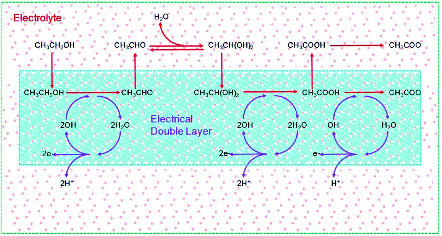 | ||
| Fig. 16 Schematic of ethanol electrooxidation in a DEFC using a Pd electrode in the presence of an electrical double layer. The red arrows represent the dehydrogenation of ethanol, while the purple arrows represent the dissociation of water. Figure adapted from ref. 125 with permission. | ||
2.3. Oxidation of polyhydric alcohols in alkaline media: ethylene glycol and glycerol
The oxidation of alcohols, especially the higher alcohols (such as EtOH, EG, and Gly), is better performed in alkaline DAFCs (ADAFCs) than in acidic DAFC devices. The reasons for the deployment of alkaline DAFCs for the higher alcohols are due to the attendant advantages of working in alkaline media, which include; (i) faster anode (AOR) and cathode (ORR) electrode kinetics with the use of non-noble metal catalysts, (ii) little or no poisoning of the non-noble metal catalysts, (iii) faster ORR at high pH, and (iv) higher power density and efficiency compared to acidic DAFCs. Indeed, the highest-performing DAFCs are the AEM-based alkaline DAFC devices.The most investigated polyhydric alcohols for alkaline DAFCs are EG and Gly, albeit some new ones, such as 1,2-propandiol, 1,3-propandiol and 1,4-butandiol,126 have recently been introduced. Most of the reports on the oxidation and mechanisms of EG and Gly have been from the group of Vizza and co-workers.127 Like ethanol, no one has been able to achieve complete oxidation of EG and Gly to CO2 or carbonate. In fact, the formation of carbonate has generally remained a minor reaction pathway, with a mixture of products being formed. Interestingly, however, Ozoemena and co-workers recently reported how an FeCo@Fe@Pd core–shell–shell nanocatalyst, supported on carboxyl-functionalized multi-walled carbon nanotubes (MWCNT-COOH), electrocatalyzed EG and Gly in an alkaline DAFC device, with high selectivity to carbonate (i.e., 67 and 73% carbonate for EG and Gly, respectively).26 Fig. 17 and 18 show the proposed mechanistic pathways for the excellent oxidation of EG and Gly, giving carbonate as the main products. For the EG, the Pd-based electrocatalysts tend to oxidize one hydroxyl group (i.e., glycolate formation, path a), with a very small amount of oxalate by direct oxidation (path b). By the small amount of oxalate observed, it may be inferred that further oxidation of the glycolate to oxalate (path d) is not preferred, but rather the formation of the carbonate with a minute amount of formate (path c). Compared to Pd/MWCNT-COOH, FeCo@Fe@Pd/MWCNT-COOH showed a stronger ability to break the C–C bond, thereby producing a larger amount of carbonate (path c).
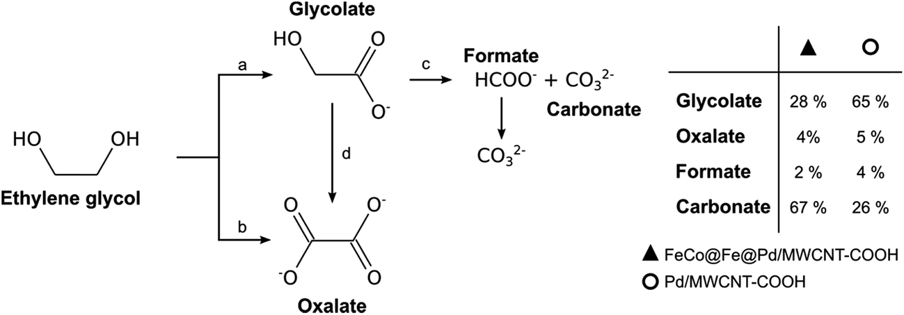 | ||
| Fig. 17 Proposed reaction pathway for EG electro-oxidation on FeCo@Fe@Pd/MWCNT-COOH and Pd/MWCNT-COOH in alkaline medium. Figure adapted from ref. 26 with permission. | ||
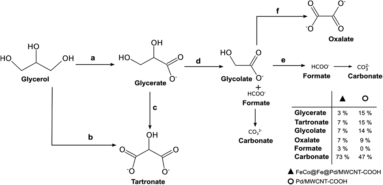 | ||
| Fig. 18 Proposed reaction pathway for G electro-oxidation on FeCo@Fe@Pd/MWCNT-COOH and Pd/MWCNT-COOH in alkaline medium. Figure adapted from ref. 26 with permission. | ||
From the products of the oxidation of Gly, we proposed that Gly is first oxidized to glycerate (path a), which is further oxidized to tartronate (path c). Direct oxidation of Gly to tartronate (path b) is also possible. By cleavage of the C–C bond, the tartronate is then converted into glycolate and formate, and finally to carbonate (path d). Also, the glyconate can be oxidised to oxalate (path f) as well as to carbonate via the formate route (path e). Interestingly, the oxidation of Gly at the FeCo@Fe@Pd/MWCNT-COOH gave significant amounts of carbonate (73%) compared to the Pd/MWCNT-COOH (47%), clearly suggesting that the Pd-based core–shell catalyst is able to completely electro-oxidize Gly with an enhanced faradaic efficiency. This finding is quite unique, especially when we consider that none of the Pd-based catalysts reported to date (such as Pd/C, PdNi/C, and PdAu/C,128 PdRh/C,129 PdAu/C and PdNi,130 and PdPtBi/C)131 showed selectivity for the total oxidation of glycerol.
3. Nanoelectrocatalysts for oxygen reduction reaction (ORR) in alkaline media
The oxygen reduction reaction (ORR) is notorious for sluggish kinetics. The poor ORR kinetics are related to a variety of factors, notably the electrolyte pH and reaction temperature. As shown in Fig. 19,132 the mechanism of the ORR in acidic and alkaline media is essentially the same: water is the final product in the direct pathway and hydrogen peroxide in the series pathway in acidic media, while the hydroxide anion is the final product in the direct pathway, with generation of peroxide in the series pathway in alkaline media. However, in alkaline media, the ORR is greatly enhanced, both thermodynamically (i.e., occurs at a more positive potential) and kinetically (i.e., due to enhanced charge transfer). Also, the highly alkaline electrolyte pH provides a less corrosive environment than the acidic media for the utilization of non-precious metal catalysts, especially for the ORR. Importantly, because these catalysts are highly selective for the ORR, the polarization losses that arise from alcohol crossover from the anode to the cathode can be completely avoided. Readers are referred to the most recent review by He and Cairns,132 where the ORR in AEM-based alcohol fuel cells has been elegantly described. Here, I will attempt to review some of the latest findings with respect to the ORR, especially with respect to the utilization of non-noble catalysts.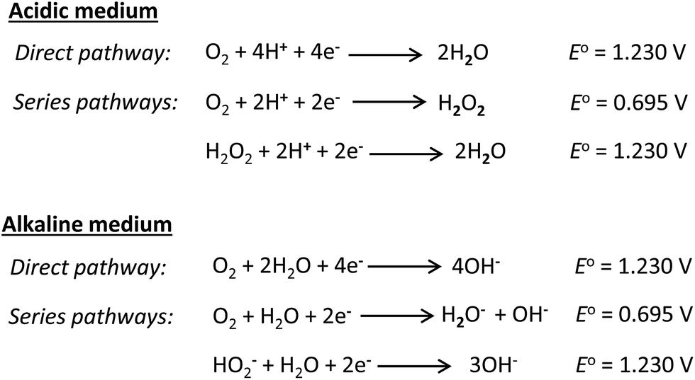 | ||
| Fig. 19 Reaction pathways for the ORR in acidic and alkaline media. | ||
In alkaline media, platinum catalysts are readily replaceable by non-noble metals (and their alloys). Non-noble metal complexes or platinum-free catalysts are generally not active toward the alcohol oxidation reaction, thus their use as cathode catalysts in ADAFCs is a huge advantage, as the consequences of alcohol cross-over to the cathode can be avoided. The Pt-free catalysts for the ORR in alkaline media can be conveniently categorized as (i) transition metal-based alloys and chalcogenides, (ii) non-noble metal oxides, (iii) metal–nitrogen (M–Nx) catalysts, and (iv) metal-free carbon materials. The common transition metals (e.g., Fe, Co, Ni, Cu, and Mn) mostly exhibit catalytic properties toward the ORR in their alloy forms, rather than their monometallic forms. Typically, these transition metals are alloyed with noble metals to improve the ORR kinetics. Metal alloying, as already described elsewhere in this review, can lead to several advantageous properties, such as changes in the surface morphology, electron density, synergistic effects, and disruption of the crystal lattice structure. Some of the transition-metal-based alloys for the ORR include FeCo@Fe@Pd/C, FeCo@Fe@Pd/MWCNTs, PdCu/rGO,133 PdNi,134 Pd2NiAg,135 Ag4Sn/C,136 and AgPd alloys.37 The popularity of Pd-based transition metal alloys is related to the fact that ORR activity in alkaline media is energetically more favourable on Pd/C than on Pt/C; the activation energy for the ORR on Pd/C (39 kJ mol−1) is smaller than recorded for the Pt/C (48 kJ mol−1) at an overpotential of 300 mV.137 However, unlike Pt/C, Pd/C has been shown to undergo oxidation under the operating conditions of the cathode. To avoid the problem of Pd oxidation, it makes sense that Pd-based alloys are explored.
Transition-metal-based chalcogenides (TMC) have been well investigated for the ORR in acidic media (PEMFC) for more than two decades, but the same cannot be said for the ORR in alkaline media. However, interestingly, new reports describing the application of TMCs for the ORR in alkaline fuel cells have continued to emerge. For example, just recently, Verjulio et al.138 reported the use of CoSe2/C as a viable catalyst in a passive, air-breathing, alkaline anion-exchange membrane micro-direct methanol fuel cell (AEM-μDMFC). The catalyst exhibited high tolerance to possible methanol cross-over, thus making the system a potentially suitable device for powering mobile devices. Also, recently, Cao et al.139 proved that Co9S8 embedded in a porous nitrogen-doped carbon matrix (Co9S8/N–C hybrid) is an efficient bi-functional catalyst for both the ORR (oxygen reduction reaction) and the OER (oxygen evolution reaction). Interestingly, the Co9S8/N–C hybrid exhibited comparable ORR activity with Pt/C (20 wt%) and superior OER activity over the state-of-the-art system, RuO2/C (20 wt%). The enhanced performance of the electrocatalyst was associated with synergistic effects arising from the covalent interaction between the Co9S8 and N–C, as well as the porosity of the N–C matrix. In a similar vein, Ma and He140 reported a new TMC catalyst, comprising Co4S3, NixS6 (7 ≥ x ≥ 6), and NiOOH nanocrystals supported on 3D nitrogen-doped graphene–carbon nanotubes (NGC), obtained by an in situ hydrothermal method. The NGC@Co4S3/NixS6 (7 ≥ x ≥ 6)/NiOOH nanohybrid catalyst exhibited enhanced ORR and OER activities over the state-of-the-art systems, 20 wt% Pt/C and RuO2/C. According to the authors, the excellent performance of the TMC system is due to the synergistic effects arising from the multiple active sites of the transition-metal nanocrystals and NGC, coupled with the inherent good conductivity and large specific surface area of the substrates.
The second category, non-noble metal oxides, used in the ORR in alkaline media, include MnOx,141–144 Cu–α-MnO2 nanowires,145 Mn3O4/NrGO nanoflakes,146 Mn3O4/NrGO nanoparticles,147 MnO2 layered nanosheets on graphene oxide,148 Fe3O4/N–C,149,150 Fe-doped Co3O4 nanofilms,151 Co–Fe3O4 hybrid nanoparticles,152 Co3O4/rGO nanorods,153 g-C3N4@CoO,154 Co–g-C3N4/graphene,155 Ni(OH)2/GO,156 Cu/TiO2,157 MnOx–Co3O4/C,158 Ni(OH)2–MnOx/C nanocomposites,159 Co2FeO4/MWCNT hollow nanostructures,160 and various spinel nanomaterials, such as NiCo2O4,161,162 ZnCo2O4/NCNT,163 CuCo2O4/N-rGO,164 CoMn2O4/PDDA–CNTs,165 CoMn2O4, and MnCo2O4.166 The MnOx-based catalysts require a special mention, especially considering the high-abundance and low-cost of manganese and its rich chemistry. From the works of Chatenet and co-workers,141–143 it is clear that nanostructured MnOx materials can show excellent ORR activity with high tolerance to ethanol in alkaline media. It has been shown by Su et al.,144 from first-principles theoretical analysis and experimental electrochemistry, that nanostructured α-Mn2O3 can serve as a viable bi-functional catalyst for the ORR and oxygen evolution reactions (OER), with the Mn3O4 and MnO2 showing an enhanced performance for the OER compared to Mn2O3. The phase and morphology in which the MnO2 exists tends to have a strong influence on its ORR activity. For example, Meng et al.167 in 2014 studied α-, β-, δ-, and amorphous MnO2 samples and showed that α-MnO2 was able to catalyse the ORR via a 4-electron pathway, while the other MnO2 could only undergo a 2-electron pathway. Interestingly, different morphologies of nanostructured α-MnO2 exhibit different performances toward ORR activity, decreasing as follows: α-MnO2 nanowire > α-MnO2 nanorod > α-MnO2 nanotube > α-MnO2 nanoparticle > α-MnO2 nanoflower. It has been shown by theory168–172 and experiment173 that oxygen-deficient β-MnO2 improves the ORR activity. For example, Cheng and co-workers showed that the introduction of oxygen vacancies in β-MnO2 material enhanced the catalytic properties of MnO2 towards the ORR in an alkaline medium (in terms of a lower overpotential and larger current response), following a quasi-4e pathway. This is an important finding, as it provides an important insight into the non-stoichiometric, oxygen-deficient MnO2 species (i.e., MnO2-δ) in oxygen electrochemistry.
The third category of ORR material is the M–Nx-based catalysts. The first M–N4 macrocyle, iron phthalocyanine (FePc), was accidentally discovered by Linstead in 1934.174 There are several works and reviews on the ORR activity on N4-macrocylic complexes. In a recent book chapter by Ozoemena and co-workers,175 the authors discussed in detail the fundamental principles of the electrocatalytic properties of N4-macrocylic complexes (metallophthalocyanines and metalloporphyrins) toward the ORR. The ORR is very sensitive to the nature of the metal centre in the M–N4 macrocycle. As depicted in Fig. 20, an oxygen molecule can interact with the metal centre of the M–N4 macrocycle via “end-on”, “side-on”, “bridge-cis” or “bridge-trans” configurations. These possible interactions can reduce the O–O bond energy, favoring its rupture.
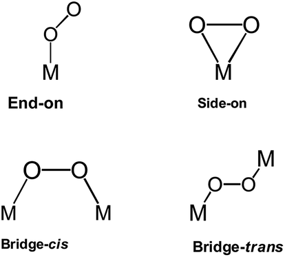 | ||
| Fig. 20 Different spatial configurations for molecular oxygen when it interacts with metal sites. | ||
The Fe and Mn phthalocyanines favour the 4-electron ORR pathway with the rupturing of the O–O bond,176–178 while the Co, Ni, and Cu phthalocyanines promote the ORR via the 2-electron mechanism. Interestingly, the electropolymerized Co(II) tetra-aminophthalocyanines promote the 4-electron pathway,179,180 while the electropolymerized Fe(II) tetra-aminophthalocyanines only favour the 2-electron pathway.181 Generally speaking, the net catalytic ORR activity of the M–N4 macrocycle is intricately linked to the central metal ion, with some degree of d-character to permit the co-ordination of the oxygen molecule. Fig. 21 is a volcano plot of the potential of the MPc complexes for the ORR in an alkaline environment at constant current versus the number of “d” electrons.182 The plot shows that MPc catalysts with d character (i.e., CrPc, MnPc, FePc, and CoPc) exhibit a higher ORR activity than those with ligand character (i.e., NiPc and CuPc). FePc complexes give the highest ORR activity in alkaline media, followed by MnPc and CoPc, confirming that transition metals with almost half-filled d-energy levels show enhanced catalysis. Thus, it is clear that a redox mechanism does not operate for those metals that cannot show the M(III)/(II) transition in the potential window examined for the ORR, as in the case for the NiPc, CuPc, and ZnPc complexes.
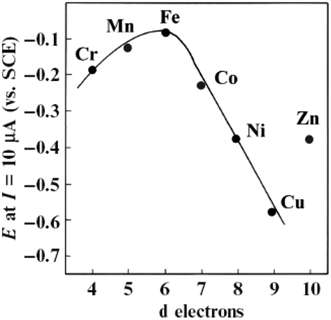 | ||
| Fig. 21 Volcano plot for the electrocatalytic activity of different M-tetrasulfonated phthalocyanines adsorbed on graphite for O2 reduction in 0.1 M NaOH, as a function of the number of d-electrons in the metal. Figure adapted from ref. 182 with permission. | ||
The ORR activity occurs within the reduction potential of the metal–O2-adduct, and the onset potential of the ORR is linked to the redox potential of the central metal; the more positive the redox potential, the higher the ORR activity. The substituents at the peripheral positions of the phthalocyanine rings have a strong influence on the MPc-based ORR. Electron-withdrawing substituents (such as the sulfonate and fluoro-groups) on the phthalocyanine ring can stabilize the singly occupied molecular orbital (SOMO), while the opposite is true for the electron-donating substituents (such as the methoxy and neopentoxy groups). In other words, electron-withdrawing groups not only decrease the electron density on the transition metal centre (i.e., creating more positive redox potential for such as Fe, Co, or Mn), but they also decrease the SOMO energy gap between the phthalocyanine and the oxygen. Electron-withdrawing functional groups on the phthalocyanine or porphyrin ring are able to shift the energy of the d-orbitals away from the Fermi level, leading to enhanced ORR activity. It should be noted that most studies on M–N4 macrocyclic catalysts involve adsorption on a carbon support to improve the ORR activity.
Many theories exist for the explanation of the ORR activity in 3d transition-metal coordinated systems and non-metal catalysts, including spin density, charge density, and defects. For M–Nx-based catalysts (such as Fe–N4 and Co–N4), their enhanced ORR activity is thought to originate from their inherent ability to anchor on defects or interplane regions of the carbon-supports. The active sites, as one should expect, are developed by the synthetic methods (e.g., pyrolysis and accompanying temperatures) used in the preparation of the catalysts. For example, it is evident from the work of Mukerjee's group183 that an optimized pyrolysis method (maximized temperature and atmosphere) is able to integrate Fe–N4 active sites into the defective pockets on the carbon support, thus enhancing the ORR activity (i.e., large shift of the Fe2+/Fe3+ redox couple and reduced ORR overpotential).
Since 2010, some researchers have continued to show that alloy-based ORR-active catalysts can be conveniently prepared from metallophthalocyanine (MPc) complexes. For example, FeCu/C,184–186 FeCo/C,187 and FeAg/C188 were prepared by simply pyrolyzing the relevant carbon-supported mixed MPc precursors (i.e., FePc, CuPc, AgPc, and CoPc) at high temperatures (600–1000 °C). These bicore MPc-based catalysts were shown to be active towards the ORR in alkaline media. Importantly, it is to be cautioned here that both the pyrolyzing temperature and atmosphere could play critical roles in the catalytic performance of the catalyst. It is possible to generate ORR-inactive metallic species if the pyrolyzing temperature exceeds a certain value.189 Also, Zhang et al.190 showed that Co-based catalysts obtained in a nitrogen atmosphere exhibited better catalysis compared to those prepared in argon or carbon dioxide atmospheres.
The next category of ORR catalysts that have begun to capture major research interest are the metal-free nanocarbons (MFNCs). The interest in MFNCs stems from the fact that most nanocarbons satisfy the critical requirements for the ORR to occur: ability to adsorb oxygen, ability to desorb reduction products, large surface area, and sufficient electronic conductivity, which confer on them the physicochemical properties to serve as powerful electron-transfer building blocks and conduits,191 and the ability to maintain electrochemical cycling stability at extreme pH values. The MFNCs that have attracted major interest include nitrogen-doped carbon nanotubes,192 nitrogen-doped carbon nanosheets,193,194 nitrogen–boron co-doped carbon nanosheets,195 carbon nitride/carbon composite spheres,196 nitrogen-doped carbon molecular sieves,197 nitrogen and sulfur co-doped carbon nanosheets,198 nitrogen-doped graphene,199–204 nitrogen-doped reduced graphene oxide,205 halogen-doped reduced graphene oxide nanosheets,206 nitrogen and fluorine co-doped reduced graphene oxide,207 nitrogen-doped carbon nanoribbons,208 nitrogen and sulfur co-doped graphene,209 boron-doped graphene,199,210 sulfur-doped graphene,211 nitrogen and phosphorus co-doped graphene,212 nitrogen and boron co-doped graphene,213–215 nitrogen-doped carbon spheres,216,217 nitrogen and sulfur co-doped carbon nanospheres,218 and nitrogen-doped carbon nanofibers,219 to mention just a few. These MFNCs have proved themselves as efficient and highly stable catalysts for the ORR in alkaline media, compared to commercial Pt/C. The performance of these nanocarbons on the ORR activity is strictly dependent on the opened structures of the MFNCs, which allow for enhanced exposure of the active sites of these heteroatoms. This is one of the findings of the recent work by Vazquez-Arenas and co-workers,220 in their theoretical and experimental investigation aimed at unravelling the catalytic nitrogen sites on graphene nanosheets for the ORR in alkaline media. However, I should mention that, despite the undeniable role of the heteroatoms on the catalytic activity of the MFCNs, residual metal nanoparticles from the adopted synthesis protocol could also play some role in the ORR activity. For example, in a recent report by Pumera and co-workers,221 it was established that the enhanced ORR activity with RGO is due to residual metal particle impurities; a similar finding was published in 2006 by the Compton group,222 for electrocatalysis at some carbon nanotube-modified electrodes.
Like the M–Nx catalyst systems, theoretical explanations for the ORR activities at MFNCs abound. The enhanced ORR activity on graphene (and CNT; after all, the difference between graphene and CNT is that graphene can be regarded as a SWCNT that has been longitudinally unzipped along its axis) is due to the defects and dopants (heteroatoms), which alter the charge density and increase the number of active sites. Lu et al.205 showed that RGO was characterized by more defects upon doping with nitrogen (N-RGO), explaining the superior performance of N-RGO over its RGO counterparts towards ORR activity. Indeed, it is now well recognised that one of the key strategies to avoid the inefficient 2-electron pathway and realize the more efficient 4-electron pathway for the ORR is to design electrocatalysts containing dopant heteroatoms and structural defects. From theoretical studies (DFT), Zhang and Xia223 proved that N-doping confers upon graphene asymmetric spin density and atomic charge density, thus making it possible for N-graphene to show superior ORR activity (4-electron pathway). Zhang et al.224 reported that the ORR activity of N-doped graphene is largely dependent on the nitrogen concentration, with a value of 24–25% achieving the favourable 4-electron transfer process.
4. MEA fabrication and AEM-DAFC: real-time operation and performance of fuel cells
Most literature reports on nanostructured catalysts for alkaline fuel cells have been based on half-cell reactions (3-electrode configurations) of alcohol oxidation or the ORR, rather than on single-cell reactions (2-electrode configurations). The performance of any fuel cell catalyst is best determined when it is subjected to single-cell operation utilizing the membrane-electrode assembly (MEA). There are a limited number of laboratories across the globe that make efforts to conduct research on AEM-DAFCs. Most MEAs fabricated for AEM-DAFCs employ commercially available AEMs, notably, those produced by Tokuyama® (A201, A901 or A-006), Solvay® and Fumatech®.According to several literature reports,132,134,225,226 the fabrication of MEAs for AEM-DAFCs follows some basic steps that can be summarised as follows. First, the catalyst ink for the anode (typically obtained by thoroughly sonicating a mixture of the Pd-based catalyst powder (≥90 wt%) and binding agent, such as PTFE (≤10 wt%) in a volatile organic solvent, such as propan-1-ol) is air-brushed onto the liquid diffusion layer (such as carbon cloth or nickel foam) to obtain the required AOR catalyst loading (typically, 1.0 mg metal per cm2). For the cathode, a sufficient amount of the ORR catalyst (typically, ≥70 wt%) is thoroughly blended with an anion-conductive ionomer (e.g., ca. 30 wt% Tokuyama's AS-4) and then uniformly sprayed onto the AEM (e.g., Tokuyama's A201). Subsequently, a gas diffusion layer (GDL), usually a carbon paper, is placed to completely cover the cathode catalyst. The components of the MEA (anode/AEM/cathode) are mechanically sandwiched in a fuel cell system using silicone-rubber gaskets to obtain efficient sealing of the system (see Fig. 22 for a typical home-made air-breathing DAFC cell, fabricated with Plexiglas and gold-plated stainless steel plates as current collectors).
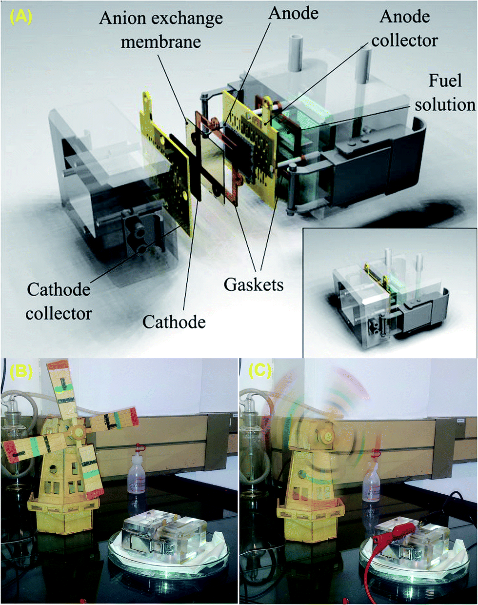 | ||
| Fig. 22 (A) Components of a home-made air-breathing DAFC cell, fabricated with Plexiglas and gold-plated stainless steel plates as current collectors, and typical laboratory demonstration of a CSIR-fabricated air-breathing DAFC driving a windmill, before (B) and after (C) completion of the circuit. Photos donated by Dr Hamish Miller (ICCOM, CNR, Italy) and Dr Mmalewane Modibedi (CSIR, South Africa). | ||
The capacity of the anode compartment is ca. 20 mL, which should allow for an actual fuel solution of ca. 10 mL. In some cases, prior to assembling the fuel cell device, it may be necessary to obtain better contact of the anode/AEM/cathode system by using a hot press (typically ∼100 °C under a pressure of ∼2 bars) for a few minutes.226 Also, prior to use, the AEM is pre-treated by first soaking in 1 M KOH solution for a few hours (ca. 2 h) at low temperature (ca. 40 °C), followed by immersing in 1 M KOH solution at ambient temperature for ca. 24 h, and finally rinsing with deionised water. The fuel cell device can be used to run both the passive and active AEM-DAFCs.
The major difference between a ‘passive AEM-DAFC’ and an ‘active AEM-DAFC’ is that the former is completely operated in ambient conditions (ca. 25 °C, in air, with the alcohol solution in the reservoir diffusing into the anode catalyst layer due to the concentration gradient existing between the reservoir and the anode), whereas the latter is more technically sophisticated and is operated under mechanical conditions (usually 25–80 °C, with the alkaline alcohol solutions and pure oxygen gas delivered to the fuel cell system at regulated or controlled flow rates, e.g., 4 mL min−1 for the alcohol solution and 200 mL min−1 for the oxygen gas). For both systems, the anode compartment is usually maintained in a nitrogen atmosphere to protect it from possible contamination from atmospheric CO2.
The performance of AEM-DAFCs (passive or active) is determined by their open-circuit voltage (OCV), peak power density, and operating temperature. Table 4 exemplifies some of the recent reports on active AEM-DAFCs based on ethanol, ethylene glycol, and glycerol, utilizing some of the catalysts already discussed in this review. Table 4 provides some insights that should be emphasized. Firstly, of the three alcohols, ethanol remains the most investigated fuel. For a greener environment, there is a need for increased research on alcohols that can be obtained from renewable biomass feedstocks (such as glycerol). Glycerol is a biodiesel-derived alcohol (i.e., a waste by-product of the transesterification reaction process for the large-scale production of biodiesel).227 Unlike other alcohols, there are very limited reports on fuel cells using EG and G as liquid fuels.
| Fuel | Anode | Cathode | Membrane | OCV/mV | Tcell/°C | Pmax/mW cm−2 | Ref. |
|---|---|---|---|---|---|---|---|
| 10% EtOH, 2 M KOH | Pd/C–CeO2 1 mg cm−2 | FeCo/C 2 mg cm−2 | A201 | 870 | 80 | 140 | 231 |
| 10% EtOH, 2 M KOH | Pd/TNTA-web 1.5 mg cm−2 | FeCo/C 2 mg cm−2 | A201 | 600 | 80 | 210 | 228 |
| 10% EtOH, 2 M KOH | Pd/TNTA-web 6 mg cm−2 | FeCo/C 2 mg cm−2 | A201 | 900 | 80 | 335 | 228 |
| EtOH 3 M, 3 M KOH | Pd/Ni-foam 3 mg cm−2 | FeCu/C 2 mg cm−2 | A201 | 870 | 60 | 164 | 232 |
| EtOH 3 M, 5 M KOH | PdNi/C 2 mg cm−2 | FeCo/C 2 mg cm−2 | A201 | 900 | 80 | 130 | 233 |
| EtOH 3 M, 5 M KOH | PdIrNi/C 1 mg cm−2 | FeCo/C 2 mg cm−2 | A201 | 900 | 60 | 92 | 121 |
| EtOH 3 M, 3 M KOH | Pd3Ru/C 1 mg cm−2 | MnO2 nanotube 2 mg cm−2 | A201 | 800 | 80 | 176 | 234 |
| 10% EG, 2 M KOH | Pd/TNTA-web 1.5 mg cm−2 | FeCo/C 2 mg cm−2 | A201 | 920 | 80 | 170 | 228 |
| 1 M EG, 7 M KOH | PdNi 1 mg cm−2 | FeCo/C 1 mg cm−2 | PBI | 90 | 112 | 235 | |
| 10% G, 2 M KOH | Pd/TNTA-web 1.5 mg cm−2 | FeCo/C 2 mg cm−2 | A201 | 940 | 80 | 160 | 228 |
Secondly, for the anodic reactions, Pd and Pd-based catalysts are the most preferred, while for the cathode reactions, Fe-based catalysts (notably, FeCo/C and FeCu/C) combined with Tokuyama's AEMs dominate current studies due to their enhancing properties in AEM-DAFCs. It is to be noted that the performance of the simple Pd/C can be enhanced by alloy formation (e.g. PdIrNi/C and FeCo@Fe@Pd/C) and exploitation of the strong metal–support interactions by utilizing some metal oxide supports (e.g. CeO2, TiO2, and Ni/NiO). The enhanced performance of Pd nanoparticles supported on titania nanotube arrays (TNTAs) requires some mention as Chen et al.228 succeeded in achieving an excellent peak power density (335 mW cm−2) for AEM-DEFC with 6 mgPd cm−2 at 80 °C.
Thirdly, the best operating conditions seem to involve the deployment of a high concentration of the electrolyte (up to 6 M KOH) and fuel concentrations in the 1–3 M alcohol range. Although a high KOH concentration is necessary for enhanced ionic conductivity for the membrane and electrode layers, and provides the necessary amount of OH− for the high-pH-dependent AOR, closer reading of some literature226,229 shows that a high KOH concentration alone is not sufficient to provide the required AEM-DAFC performance in terms of improved kinetics and mass transport. For example, Zhao and co-workers229 showed that for an ethanol-based AEM-DAFC operated with 5.0 M ethanol at 40 °C, a higher KOH concentration impacted negatively on the cell resistance, in that the cell resistance increased (from ca. 66.5 to 67.8 Ω) with an increased KOH concentration (from 1.0 to 4.5 M). According to the authors, the increased cell resistance is the result of the increased anode OH− concentration, which impedes the transport of OH− ions from the cathode to the anode. As a contrast, however, Zhang et al.230 observed that for a glycerol-based AEM-DAFC operated with 1.0 M glycerol solution at 80 °C, the cell resistance decreased at higher KOH concentrations (224.9 mΩ cm−2 at 2.0 M KOH compared to 151.9 mΩ cm−2 at 6.0 M KOH). The internal resistance of AEM-DAFCs is a function of the cathode and membrane, which is related to their degree of humidification. Both workers used similar AEMs (28 μm thick), the only difference between the two studies being that one used about 30 wt% of conductive ionomer in the fabrication of their cathode catalyst, while the other lab did not. Considering that the main function of the conductive ionomer is to enhance the electronic and ionic transport, it should perhaps not be completely surprising that the mass transport of the one is better than the other. Therefore, one can infer that the effect of a high KOH concentration on the performance of AEM-DAFCs (especially in terms of the impact on the internal resistance of the system) most likely depends on other factors, such as the type of alcohol being oxidized, operating temperatures, and electrode fabrication conditions, such as the presence of quality anion-exchange ionomers.
5. Conclusions & future perspectives
Alkaline direct alcohol fuel cells (ADAFCs) have emerged as promising electrochemical power sources for consumer and portable electronics. They represent alternative power sources to the conventional direct methanol fuel cells (DMFC) or proton-exchange membrane fuel cells (PEMFCs). Liquid alcohols (monohydric and polyhydric) are much easier to handle than hydrogen, and possess much higher volumetric energy densities than hydrogen. The emergence of anion-exchange membranes (AEMs) has continued to motivate researchers to focus on developing different kinds of nanostructured electrocatalysts for the development of high-performance ADAFCs. This review has provided some insights into the fundamental principles that allow for the intelligent design and synthesis of various types of catalysts with advantageous features, including platinum-free nanostructured electrocatalysts for the cathode and anode reactions of ADAFCs. Indeed, to improve the performance of ADAFCs in the near future (e.g., improved power output and long-term cycling) there is a need for further development of nanostructured catalysts (especially those with high Miller indices) and their promoter metal oxides, AEMs with improved physicochemical properties (improved ionic conductivity, stability, and ability to perform at ≥80 °C).Abbreviations
| AA | Ascorbic acid |
| AFC | Alkaline fuel cell (i.e., hydrogen-fed/oxygen system) |
| DAFC | Direct alcohol fuel cell (i.e., performed in acidic medium) |
| ADAFC | Alkaline direct alcohol fuel cell |
| AEM-AFC | Anion-exchange membrane alkaline fuel cell |
| AEM-ADAFC | Anion-exchange membrane alkaline direct alcohol fuel cell |
| AOR | Alcohol oxidation reaction |
| ATR-SEIRAS | Attenuated total reflectance surface-enhanced infrared absorption spectroscopy |
| BCBs | Base-treated carbon blacks |
| CBs | Carbon blacks |
| ECMF | Electrochemical milling and faceting |
| EOR | Ethanol oxidation reaction |
| EG | Ethylene glycol |
| Gly | Glycerol |
| GRR | Galvanic replacement reaction |
| MEA | Membrane-electrode assembly |
| MFNCs | Metal-free nanocarbons |
| MITNAD | Microwave-induced top-down nanostructuring and decoration |
| MOR | Methanol oxidation reaction |
| MPc | Metallophthalocyanine |
| NCBs | Neutral-treated carbon blacks |
| NCs | Nanocrystals |
| OCV | Open-circuit voltage |
| OER | Oxygen evolution reaction |
| ORR | Oxygen reduction reaction |
| SMG | Seed-mediated growth |
| SOMO | Single-occupied molecular orbital |
| SWPT | Square-wave potential treatment |
| TNTA | Titanium dioxide nanotube arrays |
Acknowledgements
This work was supported by the CSIR, South Africa. I am grateful to RSC Advances for the invitation to write this critical review, I learnt a lot during this process. The excellent comments by the reviewers are highly appreciated.References
- J. Gosselink, Int. J. Hydrogen Energy, 2002, 27, 1125–1129 CrossRef CAS.
- M. R. Modibedi, K. I. Ozoemena and M. K. Mathe, Palladium-Based Nanocatalysts for Alcohol Electro-oxidation in Alkaline Media, in Electrocatalysis in Fuel Cells: Non- and Low Platinum Approach, Lecture Notes in Energy 9, ed. Minhua Shao, Springer-Verlag, London, 2013, ch. 6, pp. 129–156 Search PubMed.
- C. Bianchini and P. K. Shen, Chem. Rev., 2009, 109, 4183–4206 CrossRef CAS PubMed.
- Electrocatalysis in Fuel Cells: Non- and Low Platinum Approach, Lecture Notes in Energy 9, ed. M. Shao, Springer-Verlag, London, 2013 Search PubMed.
- A. Tripković, K. Popović, B. Grgur, B. Blizanac, P. Ross and N. Marković, Electrochim. Acta, 2002, 47, 3707–3714 CrossRef.
- J. Prabhuram and R. Manoharan, J. Power Sources, 1998, 74, 54–61 CrossRef CAS.
- A. Aricò, V. Baglio and V. Antonucci, Electrocatal. Direct Methanol Fuel Cells From Fundam. to Appl., 2009, pp. 1–78 Search PubMed.
- Modern Aspects of Electrochemistry, ed. J. O. Bockris, B. E. Conway and R. E. White, Kluwer Academic Publishers, Boston, 2002, vol. 34 Search PubMed.
- C. Lamy, The direct ethanol fuel cell: a challenge to convert bioethanol cleanly into electric energy, 2009 Search PubMed.
- F. Bidault, D. J. L. Brett, P. H. Middleton and N. P. Brandon, J. Power Sources, 2009, 187, 39–48 CrossRef CAS.
- E. Antolini and E. R. Gonzalez, J. Power Sources, 2010, 195, 3431–3450 CrossRef CAS.
- E. Roduner, Nanoscopic Materials: Size-Dependent Phenomena, Royal Society of Chemistry, Cambridge, 2006 Search PubMed.
- Catalysis and Electrocatalysis at Nanoparticle Surfaces, ed. A. Wieckowski, E. R. Savinova and C. G. Vayenas, CRC Press, 2003 Search PubMed.
- F. J. Vidal-Iglesias, J. Solla-Gullón, E. Herrero and J. M. Feliu, Au electrocatalysis for oxygen reduction, in Electrocatalysis in Fuel Cells: A Non- and Low-Platinum Approach, Lecture Notes in Energy 9, ed. Minhua Shao, Springer-Verlag, London, 2013, ch. 7, pp. 483–512 Search PubMed.
- D. Hao, S. Xue-Zhao, S. Cheng-Min, H. Chao, X. Zhi-Chuan, L. Chen, T. Yuan, W. Deng-Ke and G. Hong-Jun, Chin. Phys. B, 2010, 19, 106104 CrossRef.
- R. Narayanan and M. A. El-Sayed, Nano Lett., 2004, 4, 1343–1348 CrossRef CAS.
- A. E. Russell, Faraday Discuss., 2009, 140, 9–10 RSC.
- S.-G. Sun, A.-C. Chen, T.-S. Huang, J.-B. Li and Z.-W. Tian, J. Electroanal. Chem., 1992, 340, 213–226 CrossRef CAS.
- G. A. Attard, J. Phys. Chem. B, 2001, 105, 3158–3167 CrossRef CAS.
- N. Tian, Z.-Y. Zhou, S.-G. Sun, Y. Ding and Z. L. Wang, Science, 2007, 316, 732–735 CrossRef CAS PubMed.
- Z. L. Wang, J. Phys. Chem. B, 2000, 104, 1153–1175 CrossRef CAS.
- M. Shao, A. Peles and K. Shoemaker, Nano Lett., 2011, 11, 3714–3719 CrossRef CAS PubMed.
- M. Mavrikakis, B. Hammer and J. Nørskov, Phys. Rev. Lett., 1998, 81, 2819–2822 CrossRef.
- W. J. Huang, R. Sun, J. Tao, L. D. Menard, R. G. Nuzzo and J. M. Zuo, Nat. Mater., 2008, 7, 308–313 CrossRef CAS PubMed.
- O. O. Fashedemi, B. Julies and K. I. Ozoemena, Chem. Commun., 2013, 49, 2034–2036 RSC.
- O. O. Fashedemi, H. A. Miller, A. Marchionni, F. Vizza and K. I. Ozoemena, J. Mater. Chem. A, 2015, 3, 7145–7156 CAS.
- M. Shao, A. Peles, K. Shoemaker, M. Gummalla, P. N. Njoki, J. Luo and C.-J. Zhong, J. Phys. Chem. Lett., 2011, 2, 67–72 CrossRef CAS PubMed.
- P. Strasser, S. Koh, T. Anniyev, J. Greeley, K. More, C. Yu, Z. Liu, S. Kaya, D. Nordlund, H. Ogasawara, M. F. Toney and A. Nilsson, Nat. Chem., 2010, 2, 454–460 CrossRef CAS PubMed.
- S. R. Calvo and P. B. Balbuena, Surf. Sci., 2007, 601, 4786–4792 CrossRef CAS.
- E. J. Lamas and P. B. Balbuena, J. Chem. Theory Comput., 2006, 2, 1388–1394 CrossRef CAS PubMed.
- J. C. Sotelo and J. M. Seminario, J. Chem. Phys., 2007, 127, 244706 CrossRef PubMed.
- R. Ferrando, J. Jellinek and R. L. Johnston, Chem. Rev., 2008, 108, 845–910 CrossRef CAS PubMed.
- L.-L. Wang and D. D. Johnson, J. Am. Chem. Soc., 2009, 131, 14023–14029 CrossRef CAS PubMed.
- H. Yamauchi, Phys. Rev. B: Condens. Matter Mater. Phys., 1985, 31, 7688–7694 CrossRef CAS.
- O. O. Fashedemi and K. I. Ozoemena, Phys. Chem. Chem. Phys., 2013, 15, 20982–20991 RSC.
- O. O. Fashedemi and K. I. Ozoemena, Electrochim. Acta, 2014, 128, 279–286 CrossRef CAS.
- D. A. Slanac, W. G. Hardin, K. P. Johnston and K. J. Stevenson, J. Am. Chem. Soc., 2012, 134, 9812–9819 CrossRef CAS PubMed.
- S. Sharma and B. G. Pollet, J. Power Sources, 2012, 208, 96–119 CrossRef CAS.
- Z. Zhang, T. Shimizu, S. Senz and U. Gösele, Adv. Mater., 2009, 21, 2824–2828 CrossRef CAS.
- Z. Qiu, H. Huang, J. Du, X. Tao, Y. Xia, T. Feng, Y. Gan and W. Zhang, J. Mater. Chem. A, 2014, 2, 8003 CAS.
- M. S. Wilson, J. Electrochem. Soc., 1993, 140, 2872 CrossRef CAS.
- K. Philippot and P. Serp, Nanomater. Catal., First edn, 2012, pp. 1–54 Search PubMed.
- X. Yuan, X.-L. Ding, C.-Y. Wang and Z.-F. Ma, Energy Environ. Sci., 2013, 6, 1105–1124 CAS.
- N. T. Cuong, A. Fujiwara, T. Mitani and D. H. Chi, Comput. Mater. Sci., 2008, 44, 163–166 CrossRef CAS.
- K. N. Wood, R. O'Hayre and S. Pylypenko, Energy Environ. Sci., 2014, 7, 1212 CAS.
- S. Kim and S. J. Park, J. Power Sources, 2006, 159, 42–45 CrossRef CAS.
- S. Kang, J. Ye and J. Chang, Int. Rev. Chem. Eng., 2013, 5, 133–144 Search PubMed.
- Z.-P. Sun, X.-G. Zhang, R.-L. Liu, Y.-Y. Liang and H.-L. Li, J. Power Sources, 2008, 185, 801–806 CrossRef CAS.
- Z. P. Sun, X. G. Zhang, Y. Y. Liang and H. L. Li, J. Power Sources, 2009, 191, 366–370 CrossRef CAS.
- M. Hara, T. Yoshida, A. Takagaki, T. Takata, J. N. Kondo, S. Hayashi and K. Domen, Angew. Chem., Int. Ed., 2004, 43, 2955–2958 CrossRef CAS PubMed.
- T. Ramulifho, K. I. Ozoemena, R. M. Modibedi, C. J. Jafta and M. K. Mathe, Electrochim. Acta, 2012, 59, 310–320 CrossRef CAS.
- T. Fujigaya, M. Okamoto and N. Nakashima, Carbon, 2009, 47, 3227–3232 CrossRef CAS.
- I. H. Hafez, M. R. Berber, T. Fujigaya and N. Nakashima, Sci. Rep., 2014, 4, 6295 CrossRef CAS PubMed.
- T. Fujigaya, C. R. Kim, K. Matsumoto and N. Nakashima, Polym. J., 2013, 45, 326–330 CrossRef CAS.
- M. R. Berber, T. Fujigaya, K. Sasaki and N. Nakashima, Sci. Rep., 2013, 3, 1764 Search PubMed.
- P. M. Ejikeme, K. Makgopa and K. I. Ozoemena, Effects of Catalyst-Support Materials on the Performance of Fuel Cells, in Nanomaterials for Fuel Cell Catalysis, ed. K. I. Ozoemena and S. Chen, Springer Publishing, New York, USA, 2016, ch. 13, pp. 517–550 Search PubMed.
- X. Wang, N. Kariuki, J. T. Vaughey, J. Goodpaster, R. Kumar and D. J. Myers, J. Electrochem. Soc., 2008, 155, B602 CrossRef CAS.
- V. Raghuveer, P. Ferreira and A. Manthiram, Electrochem. Commun., 2006, 8, 807–814 CrossRef CAS.
- H. Liu and A. Manthiram, Electrochem. Commun., 2008, 10, 740–744 CrossRef CAS.
- B. Lim, J. Wang, P. H. C. Camargo, C. M. Cobley, M. J. Kim and Y. Xia, Angew. Chem., Int. Ed., 2009, 48, 6304–6308 CrossRef CAS PubMed.
- Y. W. Lee, D. Kim, J. W. Hong, S. W. Kang, S. B. Lee and S. W. Han, Small, 2013, 9, 660–665 CrossRef CAS PubMed.
- M. Tsuji, T. Kidera, A. Yajima, M. Hamasaki, M. Hattori, T. Tsuji and H. Kawazumi, CrystEngComm, 2014, 16, 2684 RSC.
- R. C. Sekol, X. Li, P. Cohen, G. Doubek, M. Carmo and A. D. Taylor, Appl. Catal., B, 2013, 138–139, 285–293 CrossRef CAS.
- L. Xu, Z. Luo, Z. Fan, X. Zhang, C. Tan, H. Li, H. Zhang and C. Xue, Nanoscale, 2014, 6, 11738–11743 RSC.
- G.-T. Fu, C. Liu, Q. Zhang, Y. Chen and Y.-W. Tang, Sci. Rep., 2015, 5, 13703 CrossRef PubMed.
- C. Peng, Y. Hu, M. Liu and Y. Zheng, J. Power Sources, 2015, 278, 69–75 CrossRef CAS.
- N. Abbasi, P. Shahbazi and A. Kiani, J. Mater. Chem. A, 2013, 1, 9966 CAS.
- I. Bakos, A. Paszternák and D. Zitoun, Electrochim. Acta, 2015, 176, 1074–1082 CrossRef CAS.
- Y. Chen, Q.-L. Zhu, N. Tsumori and Q. Xu, J. Am. Chem. Soc., 2015, 137, 106–109 CrossRef CAS PubMed.
- M. Jin, H. Zhang, Z. Xie and Y. Xia, Angew. Chem., Int. Ed., 2011, 50, 7850–7854 CrossRef CAS PubMed.
- J. Zhang, L. Zhang, S. Xie, Q. Kuang, X. Han, Z. Xie and L. Zheng, Chemistry, 2011, 17, 9915–9919 CrossRef CAS PubMed.
- W. Niu, W. Zhang, S. Firdoz and X. Lu, Chem. Mater., 2014, 26, 2180–2186 CrossRef CAS.
- H. Zhang, M. Jin, Y. Xiong, B. Lim and Y. Xia, Acc. Chem. Res., 2013, 46, 1783–1794 CrossRef CAS PubMed.
- X. Xie, G. Gao, Z. Pan, T. Wang, X. Meng and L. Cai, Sci. Rep., 2015, 5, 8515 CrossRef CAS PubMed.
- F. J. Vidal-Iglesias, J. Solla-Gullón, E. Herrero, A. Aldaz and J. M. Feliu, Angew. Chem., Int. Ed., 2010, 49, 6998–7001 CrossRef CAS PubMed.
- Y. Ding, Y. Gao, Z. L. Wang, N. Tian, Z.-Y. Zhou and S.-G. Sun, Appl. Phys. Lett., 2007, 91, 121901 CrossRef.
- N. Tian, Z.-Y. Zhou, S.-G. Sun, Y. Ding and Z. L. Wang, Science, 2007, 316, 732–735 CrossRef CAS PubMed.
- Z.-Y. Zhou, Z.-Z. Huang, D.-J. Chen, Q. Wang, N. Tian and S.-G. Sun, Angew. Chem., Int. Ed., 2010, 49, 411–414 CrossRef CAS PubMed.
- Z.-Y. Zhou, S.-J. Shang, N. Tian, B.-H. Wu, N.-F. Zheng, B.-B. Xu, C. Chen, H.-H. Wang, D.-M. Xiang and S.-G. Sun, Electrochem. Commun., 2012, 22, 61–64 CrossRef CAS.
- N. Tian, Z.-Y. Zhou, N.-F. Yu, L.-Y. Wang and S.-G. Sun, J. Am. Chem. Soc., 2010, 132, 7580–7581 CrossRef CAS PubMed.
- P. Wang, X. Lin, B. Yang, J.-M. Jin, C. Hardacre, N.-F. Yu, S.-G. Sun and W.-F. Lin, Electrochim. Acta, 2015, 162, 290–299 CrossRef CAS.
- Y.-X. Chen, A. Lavacchi, S.-P. Chen, F. di Benedetto, M. Bevilacqua, C. Bianchini, P. Fornasiero, M. Innocenti, M. Marelli, W. Oberhauser, S.-G. Sun and F. Vizza, Angew. Chem., Int. Ed., 2012, 51, 8500–8504 CrossRef CAS PubMed.
- F. Hu, C. Chen, Z. Wang, G. Wei and P. K. Shen, Electrochim. Acta, 2006, 52, 1087–1091 CrossRef CAS.
- U. B. Demirci, J. Power Sources, 2007, 173, 11–18 CrossRef CAS.
- J. Yang, Y. Zhou, H. Su and S. Jiang, J. Electroanal. Chem., 2011, 662, 251–256 CrossRef CAS.
- T. Yajima, N. Wakabayashi, H. Uchida and M. Watanabe, Chem. Commun., 2003, 828–829 RSC.
- Z. X. Liang, T. S. Zhao, J. B. Xu and L. D. Zhu, Electrochim. Acta, 2009, 54, 2203–2208 CrossRef CAS.
- P. K. Shen and C. Xu, Electrochem. Commun., 2006, 8, 184–188 CrossRef CAS.
- C. Xu, Z. Tian, P. Shen and S. P. Jiang, Electrochim. Acta, 2008, 53, 2610–2618 CrossRef CAS.
- C. Xu, P. kang Shen and Y. Liu, J. Power Sources, 2007, 164, 527–531 CrossRef CAS.
- J. M. Jaksic, N. V. Krstajic, L. M. Vracar, S. G. Neophytides, D. Labou, P. Falaras and M. M. Jaksic, Electrochim. Acta, 2007, 53, 349–361 CrossRef CAS.
- Y. Kwon, S. C. S. Lai, P. Rodriguez and M. T. M. Koper, J. Am. Chem. Soc., 2011, 133, 6914–6917 CrossRef CAS PubMed.
- A. Zalineeva, A. Serov, M. Padilla, U. Martinez, K. Artyushkova, S. Baranton, C. Coutanceau and P. Atanassov, Electrochem. Commun., 2015, 57, 48–51 CrossRef CAS.
- Y. Cheng, Y. Liu, D. Cao, G. Wang and Y. Gao, J. Power Sources, 2011, 196, 3124–3128 CrossRef CAS.
- E. A. Batista, H. Hoster and T. Iwasita, J. Electroanal. Chem., 2003, 554–555, 265–271 CrossRef CAS.
- Z. Liu, X. Zhang and L. Hong, Electrochem. Commun., 2009, 11, 925–928 CrossRef CAS.
- K. S. Kumar, P. Haridoss and S. K. Seshadri, Surf. Coat. Technol., 2008, 202, 1764–1770 CrossRef CAS.
- P. K. Shen, C. Xu, R. Zeng and Y. Liu, Electrochem. Solid-State Lett., 2006, 9, A39–A42 CrossRef CAS.
- M. Wang, W. Liu and C. Huang, Int. J. Hydrogen Energy, 2009, 34, 2758–2764 CrossRef CAS.
- M. Fleischmann, K. Korinek and D. Pletcher, J. Electroanal. Chem. Interfacial Electrochem., 1971, 31, 39–49 CrossRef CAS.
- X. Cui, Y. Zhu, Z. Hua, J. Feng, Z. Liu, L. Chen and J. Shi, Energy Environ. Sci., 2015, 8, 1261–1266 CAS.
- E. Asghari, H. Ashassi-Sorkhabi, A. Vahed, B. Rezaei-Moghadam and G. R. Charmi, Thin Solid Films, 2016, 598, 6–15 CrossRef CAS.
- J. B. Wu, Z. G. Li, X. H. Huang and Y. Lin, J. Power Sources, 2013, 224, 1–5 CrossRef CAS.
- R. H. Tammam, A. M. Fekry and M. M. Saleh, Int. J. Hydrogen Energy, 2015, 40, 275–283 CrossRef CAS.
- G. A. Camara and T. Iwasita, J. Electroanal. Chem., 2005, 578, 315–321 CrossRef CAS.
- S. T. Nguyen, Y. Yang and X. Wang, Appl. Catal., B, 2012, 113–114, 261–270 CrossRef CAS.
- J. Liu, H. Zhou, Q. Wang, F. Zeng and Y. Kuang, J. Mater. Sci., 2011, 47, 2188–2194 CrossRef.
- H. Ji, J. Frenzel, Z. Qi, X. Wang, C. Zhao, Z. Zhang and G. Eggeler, CrystEngComm, 2010, 12, 4059 RSC.
- S. T. Nguyen, H. M. Law, H. T. Nguyen, N. Kristian, S. Wang, S. H. Chan and X. Wang, Appl. Catal., B, 2009, 91, 507–515 CrossRef CAS.
- Z. Qi, H. Geng, X. Wang, C. Zhao, H. Ji, C. Zhang, J. Xu and Z. Zhang, J. Power Sources, 2011, 196, 5823–5828 CrossRef CAS.
- Y.-C. Wei, C.-W. Liu, W.-D. Kang, C.-M. Lai, L.-D. Tsai and K.-W. Wang, J. Electroanal. Chem., 2011, 660, 64–70 CrossRef CAS.
- T. Maiyalagan and K. Scott, J. Power Sources, 2010, 195, 5246–5251 CrossRef CAS.
- Z. Zhang, L. Xin, K. Sun and W. Li, Int. J. Hydrogen Energy, 2011, 36, 12686–12697 CrossRef CAS.
- R. M. Modibedi, T. Masombuka and M. K. Mathe, Int. J. Hydrogen Energy, 2011, 36, 4664–4672 CrossRef CAS.
- W. Du, K. E. Mackenzie, D. F. Milano, N. A. Deskins, D. Su and X. Teng, ACS Catal., 2012, 2, 287–297 CrossRef CAS.
- L.-H. Jou, J.-K. Chang, T.-J. Whang and I.-W. Sun, J. Electrochem. Soc., 2010, 157, D443 CrossRef CAS.
- Y. Wang, T. S. Nguyen, X. Liu and X. Wang, J. Power Sources, 2010, 195, 2619–2622 CrossRef CAS.
- S. T. Nguyen, D. S. Ling Tan, J.-M. Lee, S. H. Chan, J. Y. Wang and X. Wang, Int. J. Hydrogen Energy, 2011, 36, 9645–9652 CrossRef CAS.
- A. O. Neto, M. M. Tusi, N. S. de Oliveira Polanco, S. G. da Silva, M. Coelho dos Santos and E. V. Spinacé, Int. J. Hydrogen Energy, 2011, 36, 10522–10526 CrossRef.
- D. Chu, J. Wang, S. Wang, L. Zha, J. He, Y. Hou, Y. Yan, H. Lin and Z. Tian, Catal. Commun., 2009, 10, 955–958 CrossRef CAS.
- S. Shen, T. S. Zhao, J. Xu and Y. Li, Energy Environ. Sci., 2011, 4, 1428 CAS.
- W. Wang, D. Chai, Y. Yang, Y. Liu, Y. Kang and Z. Lei, Int. J. Hydrogen Energy, 2015, 40, 10041–10048 CrossRef CAS.
- X. Fang, L. Wang, P. K. Shen, G. Cui and C. Bianchini, J. Power Sources, 2010, 195, 1375–1378 CrossRef CAS.
- Y. Yang, J. Ren, Q. Li, Z. Zhou, S. Sun and W. Cai, ACS Catal., 2014, 4, 798–803 CrossRef CAS.
- T. Sheng, W.-F. Lin, C. Hardacre and P. Hu, J. Phys. Chem. C, 2014, 118, 5762–5772 CAS.
- M. Bellini, M. Bevilacqua, J. Filippi, A. Lavacchi, A. Marchionni, H. A. Miller, W. Oberhauser, F. Vizza, S. P. Annen and H. Grützmacher, ChemSusChem, 2014, 7, 2432–2435 CrossRef CAS PubMed.
- A. Marchionni, M. Bevilacqua, C. Bianchini, Y.-X. Chen, J. Filippi, P. Fornasiero, A. Lavacchi, H. Miller, L. Wang and F. Vizza, ChemSusChem, 2013, 6, 518–528 CrossRef CAS PubMed.
- A. Villa, M. Plebani, M. Schiavoni, C. Milone, E. Piperopoulos, S. Galvagno and L. Prati, Catal. Today, 2012, 186, 76–82 CrossRef CAS.
- R. S. Ferreira Jr, M. Janete Giz and G. A. Camara, J. Electroanal. Chem., 2013, 697, 15–20 CrossRef.
- M. Simões, S. Baranton and C. Coutanceau, Appl. Catal., B, 2010, 93, 354–362 CrossRef.
- M. Simões, S. Baranton and C. Coutanceau, Appl. Catal., B, 2011, 110, 40–49 CrossRef.
- Q. He and E. J. Cairns, J. Electrochem. Soc., 2015, 162, F1504–F1539 CrossRef CAS.
- J.-J. Lv, S.-S. Li, A.-J. Wang, L.-P. Mei, J.-J. Feng, J.-R. Chen and Z. Chen, J. Power Sources, 2014, 269, 104–110 CrossRef CAS.
- M. Wang, W. Zhang, J. Wang, D. Wexler, S. D. Poynton, R. C. T. Slade, H. Liu, B. Winther-Jensen, R. Kerr, D. Shi and J. Chen, ACS Appl. Mater. Interfaces, 2013, 5, 12708–12715 CAS.
- S. Liu, Q. Zhang, Y. Li, M. Han, L. Gu, C. Nan, J. Bao and Z. Dai, J. Am. Chem. Soc., 2015, 137, 2820–2823 CrossRef CAS PubMed.
- Y. Lu, N. Zhang, L. An, X. Li and D. Xia, J. Power Sources, 2013, 240, 606–611 CrossRef CAS.
- L. Jiang, A. Hsu, D. Chu and R. Chen, J. Electrochem. Soc., 2009, 156, B370 CrossRef CAS.
- R. W. Verjulio, J. Santander, J. Ma and N. Alonso-Vante, Int. J. Hydrogen Energy, 2016 DOI:10.1016/j.ijhydene.2016.01.132.
- X. Cao, X. Zheng, J. Tian, C. Jin, K. Ke and R. Yang, Electrochim. Acta, 2016, 191, 776–783 CrossRef CAS.
- X.-X. Ma and X.-Q. He, Electrochim. Acta, 2016, 213, 163–173 CrossRef CAS.
- M. Chatenet, F. Micoud, I. Roche, E. Chainet and J. Vondrák, Electrochim. Acta, 2006, 51, 5452–5458 CrossRef CAS.
- A. C. Garcia, F. H. B. Lima, E. A. Ticianelli and M. Chatenet, J. Power Sources, 2013, 222, 305–312 CrossRef CAS.
- A. C. Garcia, J. J. Linares, M. Chatenet and E. A. Ticianelli, Electrocatalysis, 2013, 5, 41–49 CrossRef.
- H.-Y. Su, Y. Gorlin, I. C. Man, F. Calle-Vallejo, J. K. Nørskov, T. F. Jaramillo and J. Rossmeisl, Phys. Chem. Chem. Phys., 2012, 14, 14010–14022 RSC.
- D. J. Davis, T. N. Lambert, J. A. Vigil, M. A. Rodriguez, M. T. Brumbach, E. N. Coker and S. J. Limmer, J. Phys. Chem. C, 2014, 118, 17342–17350 CAS.
- S. K. Bikkarolla, F. Yu, W. Zhou, P. Joseph, P. Cumpson and P. Papakonstantinou, J. Mater. Chem. A, 2014, 2, 14493 CAS.
- S. Bag, K. Roy, C. S. Gopinath and C. R. Raj, ACS Appl. Mater. Interfaces, 2014, 6, 2692–2699 CAS.
- C. Shi, G.-L. Zang, Z. Zhang, G.-P. Sheng, Y.-X. Huang, G.-X. Zhao, X.-K. Wang and H.-Q. Yu, Electrochim. Acta, 2014, 132, 239–243 CrossRef CAS.
- Y. Su, H. Jiang, Y. Zhu, X. Yang, J. Shen, W. Zou, J. Chen and C. Li, J. Mater. Chem. A, 2014, 2, 7281 CAS.
- D. Zhou, L. Yang, L. Yu, J. Kong, X. Yao, W. Liu, Z. Xu and X. Lu, Nanoscale, 2015, 7, 1501–1509 RSC.
- J. Zhang, X. Wang, D. Qin, Z. Xue and X. Lu, Appl. Surf. Sci., 2014, 320, 73–82 CrossRef CAS.
- C.-H. Wang, C.-W. Yang, Y.-C. Lin, S.-T. Chang and S. L. Y. Chang, J. Power Sources, 2015, 277, 147–154 CrossRef CAS.
- M. Wang, J. Huang, M. Wang, D. Zhang, W. Zhang, W. Li and J. Chen, Electrochem. Commun., 2013, 34, 299–303 CrossRef.
- J. Jin, X. Fu, Q. Liu and J. Zhang, J. Mater. Chem. A, 2013, 1, 10538 CAS.
- Q. Liu and J. Zhang, Langmuir, 2013, 29, 3821–3828 CrossRef CAS PubMed.
- E. Farjami, M. A. Rottmayer and L. Jay Deiner, J. Mater. Chem. A, 2013, 1, 15501 CAS.
- K. Liu, Y. Song and S. Chen, Nanoscale, 2015, 7, 1224–1232 RSC.
- Y. Wang, X. Ma, L. Lu, Y. He, X. Qi and Y. Deng, Int. J. Hydrogen Energy, 2013, 38, 13611–13616 CrossRef CAS.
- Q. Wu, L. Jiang, Q. Tang, J. Liu, S. Wang and G. Sun, Electrochim. Acta, 2013, 91, 314–322 CrossRef CAS.
- J. Wang, H. L. Xin, J. Zhu, S. Liu, Z. Wu and D. Wang, J. Mater. Chem. A, 2015, 3, 1601–1608 CAS.
- Y. Xiao, C. Hu, L. Qu, C. Hu and M. Cao, Chem.–Eur. J., 2013, 19, 14271–14278 CrossRef CAS PubMed.
- Z.-Q. Liu, Q.-Z. Xu, J.-Y. Wang, N. Li, S.-H. Guo, Y.-Z. Su, H.-J. Wang, J.-H. Zhang and S. Chen, Int. J. Hydrogen Energy, 2013, 38, 6657–6662 CrossRef CAS.
- Z. Pu, Q. Liu, C. Tang, A. M. Asiri, A. H. Qusti, A. O. Al-Youbi and X. Sun, J. Power Sources, 2014, 257, 170–173 CrossRef CAS.
- R. Ning, J. Tian, A. M. Asiri, A. H. Qusti, A. O. Al-Youbi and X. Sun, Langmuir, 2013, 29, 13146–13151 CrossRef CAS PubMed.
- X. Zhai, W. Yang, M. Li, G. Lv, J. Liu and X. Zhang, Carbon, 2013, 65, 277–286 CrossRef CAS.
- P. W. Menezes, A. Indra, N. R. Sahraie, A. Bergmann, P. Strasser and M. Driess, ChemSusChem, 2015, 8, 164–171 CrossRef CAS PubMed.
- Y. Meng, W. Song, H. Huang, Z. Ren, S.-Y. Chen and S. L. Suib, J. Am. Chem. Soc., 2014, 136, 11452–11464 CrossRef CAS PubMed.
- J. A. Dawson and I. Tanaka, ACS Appl. Mater. Interfaces, 2014, 6, 17776–17784 CAS.
- D. a. Tompsett, S. C. Parker and M. S. Islam, J. Am. Chem. Soc., 2014, 136, 1418–1426 CrossRef CAS PubMed.
- L. Li, X. Feng, Y. Nie, S. Chen, F. Shi, K. Xiong, W. Ding, X. Qi, J. Hu, Z. Wei, L.-J. Wan and M. Xia, ACS Catal., 2015, 4825–4832 CrossRef CAS.
- J. A. Dawson, H. Chen and I. Tanaka, ACS Appl. Mater. Interfaces, 2015, 7, 1726–1734 CAS.
- D. Tompsett and M. Islam, J. Phys. Chem. C, 2014, 25009–25015 CAS.
- F. Cheng, T. Zhang, Y. Zhang, J. Du, X. Han and J. Chen, Angew. Chem., Int. Ed., 2013, 52, 2474–2477 CrossRef CAS PubMed.
- R. P. Linstead, J. Chem. Soc., 1934, 1016 RSC.
- J. Masa, K. I. Ozoemena, W. Schuhmann and J. H. Zagal, Fundamental Studies on the Electrocatalytic Properties of Metal Macrocyclics and Other Complexes for the Electroreduction of O2, in Electrocatalysis in Fuel Cells: A Non- and Low-Platinum Approach, Lecture Notes in Energy 9, ed. Minhua Shao, Springer-Verlag, London, 2013, ch. 7, pp. 157–212 Search PubMed.
- J. Zagal, M. Páez, A. A. Tanaka, J. R. dos Santos and C. A. Linkous, J. Electroanal. Chem., 1992, 339, 13–30 CrossRef CAS.
- J. H. Zagal, Coord. Chem. Rev., 1992, 119, 89–136 CrossRef CAS.
- Y.-H. Tse, P. Janda, H. Lam, J. Zhang, W. J. Pietro and A. B. P. Lever, J. Porphyrins Phthalocyanines, 1997, 1, 3–16 CrossRef CAS.
- G. Ramírez, E. Trollund, M. Isaacs, F. Armijo, J. Zagal, J. Costamagna and M. Aguirre, Electroanalysis, 2002, 14, 540–545 CrossRef.
- J. Pavez, M. Paez, A. Ringuede, F. Bedioui and J. H. Zagal, J. Solid State Electrochem., 2004, 9, 21–29 CrossRef.
- G. Lalande, R. Côté, D. Guay, J. P. Dodelet, L. T. Weng and P. Bertrand, Electrochim. Acta, 1997, 42, 1379–1388 CrossRef CAS.
- J. H. Zagal, S. Griveau, J. F. Silva, T. Nyokong and F. Bedioui, Coord. Chem. Rev., 2010, 254, 2755–2791 CrossRef CAS.
- N. Ramaswamy, U. Tylus, Q. Jia and S. Mukerjee, J. Am. Chem. Soc., 2013, 135, 15443–15449 CrossRef CAS PubMed.
- M. Piana, M. Boccia, A. Filpi, E. Flammia, H. A. Miller, M. Orsini, F. Salusti, S. Santiccioli, F. Ciardelli and A. Pucci, J. Power Sources, 2010, 195, 5875–5881 CrossRef CAS.
- Q. He, X. Yang, X. Ren, B. E. Koel, N. Ramaswamy, S. Mukerjee and R. Kostecki, J. Power Sources, 2011, 196, 7404–7410 CrossRef CAS.
- Q. He, X. Yang, R. He, A. Bueno-López, H. Miller, X. Ren, W. Yang and B. E. Koel, J. Power Sources, 2012, 213, 169–179 CrossRef CAS.
- V. Bambagioni, C. Bianchini, J. Filippi, A. Lavacchi, W. Oberhauser, A. Marchionni, S. Moneti, F. Vizza, R. Psaro, V. Dal Santo, A. Gallo, S. Recchia and L. Sordelli, J. Power Sources, 2011, 196, 2519–2529 CrossRef CAS.
- H. A. Miller, M. Bevilacqua, J. Filippi, A. Lavacchi, A. Marchionni, M. Marelli, S. Moneti, W. Oberhauser, E. Vesselli, M. Innocenti and F. Vizza, J. Mater. Chem. A, 2013, 1, 13337 CAS.
- L. Li, X. Yuan, Z. Ma and Z.-F. Ma, J. Electrochem. Soc., 2015, 162, F359–F365 CrossRef CAS.
- H.-J. Zhang, H. Li, X. Li, B. Zhao, Z.-F. Ma and J. Yang, Electrochim. Acta, 2014, 115, 1–9 CrossRef CAS.
- K. Lawrence, C. L. Baker, T. D. James, S. D. Bull, R. Lawrence, J. M. Mitchels, M. Opallo, O. A. Arotiba, K. I. Ozoemena and F. Marken, Chem.–Asian J., 2014, 9, 1226–1241 CrossRef CAS PubMed.
- K. Gong, F. Du, Z. Xia, M. Durstock and L. Dai, Science, 2009, 323, 760–764 CrossRef CAS PubMed.
- W. Wei, H. Liang, K. Parvez, X. Zhuang, X. Feng and K. Müllen, Angew. Chem., 2014, 126, 1596–1600 CrossRef.
- Q. Liu, Y. Duan, Q. Zhao, F. Pan, B. Zhang and J. Zhang, Langmuir, 2014, 30, 8238–8245 CrossRef CAS PubMed.
- Y. Zhang, X. Zhuang, Y. Su, F. Zhang and X. Feng, J. Mater. Chem. A, 2014, 2, 7742 CAS.
- X. Fu, X. Hu, Z. Yan, K. Lei, F. Li, F. Cheng and J. Chen, Chem. Commun., 2016, 52, 1725–1728 RSC.
- N. López-Salas, M. C. Gutiérrez, C. O. Ania, M. A. Muñoz-Márquez, M. Luisa Ferrer and F. del Monte, J. Mater. Chem. A, 2016, 4, 478–488 Search PubMed.
- K. Qu, Y. Zheng, S. Dai and S. Z. Qiao, Nano Energy, 2016, 19, 373–381 CrossRef CAS.
- X. Xu, T. Yuan, Y. Zhou, Y. Li, J. Lu, X. Tian, D. Wang and J. Wang, Int. J. Hydrogen Energy, 2014, 39, 16043–16052 CrossRef CAS.
- B. Zheng, J. Wang, F.-B. Wang and X.-H. Xia, Electrochem. Commun., 2013, 28, 24–26 CrossRef CAS.
- D. W. Chang, H.-J. Choi and J.-B. Baek, J. Mater. Chem. A, 2015, 3, 7659–7665 CAS.
- K. Parvez, S. Yang, Y. Hernandez, A. Winter, A. Turchanin, X. Feng and K. Müllen, ACS Nano, 2012, 6, 9541–9550 CrossRef CAS PubMed.
- Z. Lin, G. H. Waller, Y. Liu, M. Liu and C. Wong, Nano Energy, 2013, 2, 241–248 CrossRef CAS.
- W. Yan, L. Wang, C. Chen, D. Zhang, A.-J. Li, Z. Yao and L.-Y. Shi, Electrochim. Acta, 2016, 188, 230–239 CrossRef CAS.
- Z.-J. Lu, M.-W. Xu, S.-J. Bao, K. Tan, H. Chai, C.-J. Cai, C.-C. Ji and Q. Zhang, J. Mater. Sci., 2013, 48, 8101–8107 CrossRef CAS.
- K. Kakaei and A. Balavandi, J. Colloid Interface Sci., 2016, 463, 46–54 CrossRef CAS PubMed.
- X. Qiao, S. Liao, G. Wang, R. Zheng, H. Song and X. Li, Carbon, 2016, 99, 272–279 CrossRef CAS.
- M. Liu, Y. Song, S. He, W. W. Tjiu, J. Pan, Y.-Y. Xia and T. Liu, ACS Appl. Mater. Interfaces, 2014, 6, 4214–4222 CAS.
- Z. Zuo, W. Li and A. Manthiram, J. Mater. Chem. A, 2013, 1, 10166 CAS.
- Z.-H. Sheng, H.-L. Gao, W.-J. Bao, F.-B. Wang and X.-H. Xia, J. Mater. Chem., 2012, 22, 390–395 RSC.
- Z. Yang, Z. Yao, G. Li, G. Fang, H. Nie, Z. Liu, X. Zhou, X. Chen and S. Huang, ACS Nano, 2012, 6, 205–211 CrossRef CAS PubMed.
- G. Jo, J. Sanetuntikul and S. Shanmugam, RSC Adv., 2015, 5, 53637–53643 RSC.
- J. Tai, J. Hu, Z. Chen and H. Lu, RSC Adv., 2014, 4, 61437–61443 RSC.
- J. Han, J. Y. Cheon, S. H. Joo and S. Park, Solid State Sci., 2014, 33, 1–5 CrossRef CAS.
- J. Jin, F. Pan, L. Jiang, X. Fu, A. Liang, Z. Wei, J. Zhang and G. Sun, ACS Nano, 2014, 8, 3313–3321 CrossRef CAS PubMed.
- Y. Li, T. Li, M. Yao and S. Liu, J. Mater. Chem., 2012, 22, 10911 RSC.
- Y.-L. Liu, C.-X. Shi, X.-Y. Xu, P.-C. Sun and T.-H. Chen, J. Power Sources, 2015, 283, 389–396 CrossRef CAS.
- C. You, S. Liao, H. Li, S. Hou, H. Peng, X. Zeng, F. Liu, R. Zheng, Z. Fu and Y. Li, Carbon, 2014, 69, 294–301 CrossRef CAS.
- J. Yin, Y. Qiu, J. Yu, X. Zhou and W. Wu, RSC Adv., 2013, 3, 15655 RSC.
- J. Vazquez-Arenas, A. Galano, D. U. Lee, D. Higgins, A. Guevara-García and Z. Chen, J. Mater. Chem. A, 2016, 4, 976–990 CAS.
- L. Wang, C. K. Chua, B. Khezri, R. D. Webster and M. Pumera, Electrochem. Commun., 2016, 62, 17–20 CrossRef CAS.
- C. E. Banks, A. Crossley, C. Salter, S. J. Wilkins and R. G. Compton, Angew. Chem., Int. Ed., 2006, 45, 2533–2537 CrossRef CAS PubMed.
- L. Zhang and Z. Xia, J. Phys. Chem. C, 2011, 115, 11170–11176 CAS.
- Y. Zhang, J. Ge, L. Wang, D. Wang, F. Ding, X. Tao and W. Chen, Sci. Rep., 2013, 3, 2771 Search PubMed.
- V. Bambagioni, C. Bianchini, A. Marchionni, J. Filippi, F. Vizza, J. Teddy, P. Serp and M. Zhiani, J. Power Sources, 2009, 190, 241–251 CrossRef CAS.
- R. M. Modibedi, T. Mehlo, K. I. Ozoemena and M. K. Mathe, Int. J. Hydrogen Energy, 2015, 40, 15605–15612 CrossRef CAS.
- J. Van Gerpen, Fuel Process. Technol., 2005, 86, 1097–1107 CrossRef CAS.
- Y. Chen, M. Bellini, M. Bevilacqua, P. Fornasiero, A. Lavacchi, H. A. Miller, L. Wang and F. Vizza, ChemSusChem, 2015, 8, 524–533 CrossRef CAS PubMed.
- Y. S. Li, T. S. Zhao and Z. X. Liang, J. Power Sources, 2009, 187, 387–392 CrossRef CAS.
- Z. Zhang, L. Xin, J. Qi, D. J. Chadderdon and W. Li, Appl. Catal., B, 2013, 136–137, 29–39 CrossRef CAS.
- V. Bambagioni, C. Bianchini, Y. Chen, J. Filippi, P. Fornasiero, M. Innocenti, A. Lavacchi, A. Marchionni, W. Oberhauser and F. Vizza, ChemSusChem, 2012, 5, 1266–1273 CrossRef CAS PubMed.
- Y. Li and Y. He, RSC Adv., 2014, 4, 16879 RSC.
- Y. S. Li and T. S. Zhao, Int. J. Hydrogen Energy, 2011, 36, 7707–7713 CrossRef CAS.
- L. Ma, H. He, A. Hsu and R. Chen, J. Power Sources, 2013, 241, 696–702 CrossRef CAS.
- L. An, L. Zeng and T. S. Zhao, Int. J. Hydrogen Energy, 2013, 38, 10602–10606 CrossRef CAS.
| This journal is © The Royal Society of Chemistry 2016 |