Towards cost-effective silicon anodes using conductive polyaniline-encapsulated silicon micropowders

Xin Zhao*, Minjie Li, Nicole Ross and Yu-Ming Lin
Bluestone Global Tech, 169 Myers Corners Road, Wappingers Falls, NY 12590, USA. E-mail: vacxzhao@gmail.com

Received 3rd June 2016 , Accepted 9th August 2016

First published on 10th August 2016


Abstract

To overcome the remaining issues of nanostructured Si anodes such as compromised packing density and prohibitive cost associated with sophisticated structural designs and synthetic approaches, we investigated the feasibility towards practically viable Si anodes by combining low-cost material precursors with facile and scalable mechanical grinding and solution processes. By encapsulating Si particles in a conductive polyaniline matrix that serves as an effective buffer layer, we demonstrate stable capacities along with enhanced efficiency and volumetric energy output from solar-grade Si granule-derived Si micropowders. A systematic comparative study with nano-sized Si counterparts presents competitive cost weighted performance for the Si micropowder-enabled anode systems, which offers the potential for realizing high-performance, cost-effective lithium-ion batteries.

The electrochemical alloying/de-alloying reactions between silicon and lithium ions are accompanied with dramatic volume expansion/contraction due to the accommodation of a large amount of Li ions in the Si host.1 To address the rapid mechanical and chemical degradation of Si anodes arising from colossal volume variation, research has been directed into engineering of Si-based nanostructures with finely controlled morphologies that are more tolerant to lithiation induced fracturing.2–4 Despite the enhanced laboratory performance achieved, there are several crucial issues towards the practical deployment of Si anodes whose importance is often overlooked and which are difficult for nanostructured Si anodes. These issues include: (1) the low cycling efficiency resulting from the huge gravimetric specific surface area and consequently intensified parasitic side reactions, (2) the compromised volumetric capacity consequential of reduced packing densities, and (3) the employment of inherently expensive source materials or elaborate i.e. high-temperature and low-throughput synthetic approaches that do not permit scalable and affordable manufacturing.5–8

In order to realize the potential of Si fully while lifting the restriction of scalability placed by the materials and processing routes, low-grade Si sources such as metallurgical Si and iron-containing ferrosilicon have been explored lately.9–11 The coarse Si powders were treated by chemical etching and converted into new forms of porous Si monolithic that were capable of accommodating the volume variation during cycling. However, to remove the undesirable metallic impurities and create inward void space, use of hazardous hydrofluoric acid was inevitably involved. The potential safety concern may become more acute when large-scale application is considered. Another approach is to encapsulate micron-sized Si powders with or without porosity in a conductive carbonaceous shell12–14 or polymer network7,15–18 that prevents the ruptured particles from electrical isolation. The use of polymers such as conductive or self-healing polymers offers additional advantages by allowing room temperature processing, whereas specially designed macromolecular structures were often needed and therefore issues for scaling up remain. Furthermore, electrode fading may still occur as the areal mass loading increases to a practically meaningful level.19,20

Herein we investigate the feasibility towards practically viable Si anode by employing low-cost and more environmentally benign materials and processes. By combining mechanical milling and solution-based polymerization at room temperature, we developed a Si composite anode comprising Si particles encapsulated in a conductive polyaniline matrix. A comparative analysis on nano-sized and micron-sized Si shows that the conductive polymer matrix provides an effective protection to Si particles with a broad size range. Formulating the active material with graphite additives further enhances the adaptability of large and dense Si particles, and we have successfully applied solar-grade polycrystalline Si granules (∼99.99% Si, $10 USD per kg) as the starting material, which is readily available in ton quantities21 and requires no purification. Our electrochemical study and cost estimation demonstrates competitive cost-weighted performance22 of the modified solar-grade bulk Si, which can potentially serve as a cost-effective Si anode for energy storage.

Si nanopowders (∼100 nm, Sigma-Aldrich) and polycrystalline Si granules (99.99%, ∼20 mesh, MEMC) were used as starting materials and processed in parallel for comparative purposes. The Si nanopowders were applied as received. The polycrystalline Si powders were ground mechanically with N-methyl-2-pyrrolidone (NMP, Sigma-Aldrich) on a 2 L planetary ball mill (Across International, PQ-N2) with a rotation speed of 300 rpm. The ball[thin space (1/6-em)]:[thin space (1/6-em)]solvent[thin space (1/6-em)]:[thin space (1/6-em)]powder mass ratio was set to 4[thin space (1/6-em)]:[thin space (1/6-em)]1[thin space (1/6-em)]:[thin space (1/6-em)]1. After 24 hours of milling under ambient atmosphere, the Si powders were separated and washed with acetone by centrifugation, and subsequently dispersed in an aqueous solution of aniline monomer and L-phenylalanine. Typically, 8 g milled Si powders were added into 60 mL water containing 0.45 g L-phenylalanine (Sigma-Aldrich) under vigorous stirring, followed by addition of 0.84 g aniline (Sigma-Aldrich). Then 30 mL 0.125 M ammonium persulfate aqueous solution was injected dropwise, and the mixture was kept at room temperature under stirring for overnight, followed by centrifugation and washing with water and isopropanol. The collected solid products were vacuum dried at 90 °C thoroughly. The PANI treated nano-sized Si and milled ∼20 mesh Si composites are denoted as “nm-Si@PANI” and “μm-Si@PANI”, respectively.

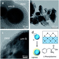
The morphology of PANI coated Si powders was determined by JEM-2100F transmission electron microscopy (TEM), as shown in Fig. 1a–c. The as-received Si nanoparticles were spherical and monodispersed, while the ball milled ∼20 mesh Si was populated with sub-micron to 3 μm-sized particles possessing a relatively broad size distribution and irregular morphology. Owing to a native oxide layer on their surface, the amphiphilic Si particles were readily dispersible in the aqueous solution. Phenylalanine is a prevalent amino acid (Fig. 1d), in which the carboxylic acid and amino groups can graft onto the SiOx surface and form self-healable hydrogen bonds with Si.23–25 The in situ polymerization of aniline monomers took place rapidly in the presence of the oxidative initiator, leading to ∼10–20 nm thick conformal coating around the Si cores. The Si particles were partially fused by the polymer layer during synthesis. Doping of PANI by the hydrophobic chains of phenylalanine might have arisen during cross-linking,26,27 which could enhance the electrical conductivity and structural integrity of the composites further. Raman spectra were recorded on the resulting products by a WiTec alpha500 automated confocal Raman microscope at 532 nm laser excitation, which showed the characteristic peaks of polymerized aniline (Fig. S1). The Si content in the composite was estimated to be 75 wt% based on weight losses upon organic combustion under flowing air in thermogravimetric analysis.


image file: c6ra14386e-f1.tif
Fig. 1 TEM images of (a) PANI coated nm-Si particles, (b) PANI coated μm-Si particles at low magnification, and (c) PANI coated μm-Si particles at high magnification showing the uniform PANI layer. (d) Schematics of Si particles encapsulated within conformal PANI coatings. The oxygen-terminated SiOx surface interacted with the L-phenylalanine molecules through hydrogen bonding, enabling uniform PANI coating.

After removal of residual reactants, the PANI coated Si particles were firstly formulated with a poly(acrylic acid) binder (PAA, Mw ∼ 3[thin space (1/6-em)]000[thin space (1/6-em)]000, Sigma-Aldrich) in the absence of additional conductive agents. The working electrode was fabricated by tape casting a mixture of PANI coated Si particles and PAA with a mass ratio of 90[thin space (1/6-em)]:[thin space (1/6-em)]10 onto a 9 μm-thick copper foil. The total mass loading was of the order of 3–5 mg cm−2, and the electrodes were calendered and dried at 90 °C for 12 h under vacuum prior to cell assembly in an Ar-filled glovebox. Electrochemical charge/discharge measurements were examined by galvanostatic cycling using a CR2032-type coin cell with metallic lithium as the counter electrode. A Whatman borosilicate glass fiber membrane soaked with an electrolyte of 1 M LiPF6 per ethylene carbonate (EC) per dimethyl carbonate (DMC) (1[thin space (1/6-em)]:[thin space (1/6-em)]1 v/v) plus 10 vol% fluoroethylene carbonate (FEC) was used as the separator. The cells were subject to deep galvanostatic charge/discharge cycling on a Maccor Series 4000 automated test system between 1.5 and 0.02 V vs. Li/Li+.

Fig. 2 depicts the capacity and cycling stability of nm-Si@PANI and μm-Si@PANI composite electrodes. When cycled at a constant current of 0.5 A g−1 (corresponding to ∼0.2C-rate based on the theoretical capacity of 3579 mA h g−1 for Si),28 the nm-Si@PANI composite exhibited an initial coulombic efficiency (CE) of ∼60% and a relatively stable reversible capacity of ∼1000 mA h g−1 during long-term cycling. The initial capacity losses were primarily caused by electrolyte decomposition and irreversible reactions of Li ions with the SiOx and residual surface groups.5 By contrast, the initial CE of the μm-Si@PANI composite was 55%, and the capacity increased steadily from 400 to 650 mA h g−1 upon cycling for 200 times. The stepwise increase of capacity can be ascribed to the gradual wetting of PANI sheathed Si by the carbonate electrolyte,15 along with fracturing of Si particles that induced fresh surfaces for electrolyte diffusion and ion insertion. The unprotected Si, however, deactivated severely during successive charge/discharge reactions regardless of particle sizes. This indicates that the conductive and ductile network consolidated by PANI confined the micron-sized Si particles and their broken pieces, which inhibited electrode deformation, as illustrated in Fig. 2c. Meanwhile, the ion-permeable PANI coating serves as a conformal conductive media for fast transport of electrons and Li ions. The PANI chains possessed interspaces for Li ion diffusion,29 and the swelling of the PANI shells during cycling further promoted the rate of ion diffusion.30 The topographic feature and ability of conductive polymers to expand and shrink coherently with the Si particles assisted in maintaining a good electronic and ionic conductivity during cycling.7,31 It is noteworthy that reducing the content of PANI by half engendered incomplete coverage of the irregular Si particles (Fig. S2a), while increasing the PANI content significantly hampered electrolyte wetting, and compromised the overall capacity and cycling efficiency (Fig. S2b and c).


image file: c6ra14386e-f2.tif
Fig. 2 Delithiation capacity (solid) and coulombic efficiency (open) of electrodes prepared using (a) nm-Si and (b) μm-Si particles with and without PANI coating cycled from 1.5 V to 0.02 V at a current density of 0.5 A g−1. Capacity is calculated using the total mass of Si and PANI. (c) Schematic drawing showing the morphological changes of μm-Si particles with and without PANI coating during cycling. The PANI coating confines the fractured pieces of Si particles.

In order to further suppress the disintegration of Si micropowders, partially exfoliated graphite flakes (Asbury, Fig. S3) were introduced into the μm-Si@PANI composite via an additional ball milling step. Such thin-flake graphite is an analog to graphene platelets while being more ordered and abundant.32,33 The dry powders were ball milled for 2 hours at a rotation speed of 300 rpm, and the ball[thin space (1/6-em)]:[thin space (1/6-em)]powder mass ratio was 1[thin space (1/6-em)]:[thin space (1/6-em)]1. The surface topology of μm-Si@PANI particles before and after milling with graphite is shown in the scanning electron microscopy (SEM) images in Fig. 3a and b. The interconnected graphitic layers with extreme width-to-thickness aspect ratios (∼5000–10[thin space (1/6-em)]000) constructed into a highly conductive structural platform for anchoring the μm-Si@PANI particles. Intimate contact between the graphitic matrix and particles was generated owing to the energy from the mechanical agitation and the affinity of PANI towards graphitic carbon.34 By pasting the aqueous slurry of the μm-Si@PANI/graphite composite and PAA binder onto copper foils, smooth electrode films were obtained, as shown in Fig. 3c and d. Attributed to the horizontally oriented and compact graphite flakes, the compression density of the films approached 1.2 g cm−3 after calendering, in contrast to ∼0.9 g cm−3 and 0.7 g cm−3 for solely μm-Si@PANI and nm-Si@PANI electrodes, respectively.


image file: c6ra14386e-f3.tif
Fig. 3 SEM images of (a) PANI coated μm-Si particles and (b) PANI coated μm-Si/graphite composites showing the particles uniformly distributed on the basal plane of graphite flakes. (c) Digital photograph of large-area PANI coated μm-Si/graphite composite coatings on a 15 cm × 28 cm copper foil current collector. (d) Schematic drawing of PANI coated μm-Si particles embedded in a matrix comprising interconnected graphite flakes.

The cycling performance of μm-Si@PANI composites incorporating graphite at three different weight loadings is presented in Fig. 4a and b. All the composites were characterized by an improved initial CE of above 70% and little capacity fading during prolonged cycling. Among them, the composite electrode consisting of 60 wt% μm-Si@PANI and 30 wt% graphite displayed a high initial CE of 73%, along with the largest reversible capacity exceeding 600 mA h g−1 and minimal decay when cycled at 0.5 A g−1 (∼0.27C). At a higher rate of 2.5 A g−1 (∼1.4C), a reversible capacity beyond 500 mA h g−1 was shown in the beginning, which slowly declined to 383 mA h g−1 after 300 cycles, corresponding to a capacity loss of 0.08% per cycle on average. Note that the areal capacity of the electrode films attained 2.7 mA h cm−2, which is typically higher than published results.3,7,10–12,15–18 Nonetheless, the capacity decay was much less significant in our case, given the high areal loading. The volumetric capacity of μm-Si@PANI/graphite composite surpassed that of the nm-Si@PANI owing to the higher compression density. Since polymers tend to degrade during storage,35 cycling tests were repeated on electrodes that were stored in air (relative humidity ∼ 60%) for 60 days (Fig. S4). The stable reversible capacity was reproducible, confirming that the composites do not undergo severe degradation when stored in the ambient atmosphere.


image file: c6ra14386e-f4.tif
Fig. 4 Delithiation capacity (solid) and coulombic efficiency (open) of PANI coated μm-Si/graphite composite electrodes cycled at current densities of (a) 0.5 A g−1 and (b) 2.5 A g−1. Capacity is calculated using the total mass of Si, PANI and graphite. (c) Galvanostatic charge/discharge voltage profiles of PANI coated μm-Si/graphite composite electrodes at 0.5 A g−1. (d) Nyquist plots of PANI coated μm-Si and PANI coated μm-Si/graphite composite electrodes after 50 cycles at 0.5 A g−1.

The shape of the charge/discharge voltage profiles of the composite electrode resemble common observations with Si-based electrodes,3,5,25 and was not changed by the presence of PANI or graphite (Fig. 4c). However, the ohmic polarization behavior appeared to be ameliorated markedly by introducing graphite, which ensured an effective usage and improved charge/discharge reversibility of the active material (Fig. S5 and Table S1). At 0.5 A g−1, the capacity contribution from graphite was ∼60 mA h g−1 (Fig. S6). Despite a reduction of Si content from 68 wt% to 45 wt% in the finished electrodes due to the addition of graphite, the real capacity of Si was boosted from 530–800 mA h g−1 to 1140 mA h g−1. The enhanced coulombic efficiency can be further attributed to the graphite and PANI “dual protection” that assisted in the formation of more stable SEI layers on the electrodes. The existence of an optimum μm-Si@PANI and graphite content is indicative of balanced charge storage behavior, conductivity and structural integrity.

The positive role of graphite in enabling a high electrode utilization and stability is further evidenced by electrochemical impedance spectroscopy. The electrochemical impedance spectroscopy (EIS) measurements were conducted using an Ametak VersaSTAT3 potentiostat/galvanostat by applying an AC voltage of 10 mV amplitude and DC open circuit voltage (OCV) in the frequency range of 100 kHz to 0.01 Hz. The Nyquist plots on delithiated electrodes showed depressed semi-circles at the high-frequency regime of 100 kHz to 10 Hz and nearly straight lines at frequencies below 10 Hz (Fig. 4d), which correlated with the charge-transfer and diffusion kinetic-controlled regions, respectively. This is in line with previous studies on Si nanostructures,36 and an identical equivalent circuit can be applied to fit into the plots. The μm-Si@PANI electrode without graphite displayed a much widened semi-circle and inclined Warburg region37 after cycling compared to the μm-Si@PANI/graphite composite, implying pronouncedly higher charge-transfer and diffusion resistances during the lithiation/delithiation processes. As graphite is a more effective electronic conductor than delithiated amorphous Si and PANI, it has reinforced the electrical contact at the interfaces and promoted electron transport throughout the electrode films, which is consistent with the suppressed polarization afore described. Moreover, the internal resistance determined from the intersection of the high-frequency curves with the real axis was 22.2, 4.2 and 4.9 Ω for the bare μm-Si, μm-Si@PANI and μm-Si@PANI/graphite electrodes after cycling, respectively (Fig. S7), which agrees with the low conductivity and unstable interface of the unprotected Si electrode.

Due to the comparatively large particle size and existence of Si aggregates, the maximum gravimetric capacity of μm-Si in the engineered composite electrodes was lower than that of nano-Si (1140 mA h g−1 vs. 1600 mA h g−1) and what generally claimed in nanostructured Si anode. Employing high-energy grinding and/or hard grinding media such as boron carbide nano/micro-millers38 would further narrow down the particle size distribution of Si, and thus improve electrode utilization and alleviate degradation. However, the cost benefit of the μm-Si electrode design is broadly compelling. A preliminary assessment of the total costs of Si nano and micropowder-based electrodes is included in Table S2. The cost estimations and comparisons are based on the retail price of Si sources and chemical precursors, as well as energy consumption of laboratory scale processing. Presumably, these costs could be reduced commensurately if the materials are purchased in bulk and the fabrication routes are tuned to high-volume production. However, in the absence of robust citable cost data, it is reasonable to conclude based on the actual costs in our work that the μm-Si electrodes will likely offer attractive cost weighted performance compared to nm-Si based systems.

Conclusions

A Si composite anode constructed from Si particles encapsulated in a conductive polyaniline matrix was prepared by combining facile mechanical grinding and solution process, which achieved enhanced capacity and cycling stability. Further incorporating conductive and compact graphite flakes into the electrode enabled excellent performance and high utilization of micron-sized Si particles derived from low-cost solar-grade Si, by promoting the electron conduction and improving the structural stability. The combination of materials and preparation protocol developed in our work led to a good cost-performance balance, which would offer a prospect of addressing the practical barriers confronting the deployment of Si-based anode on a large scale.

Notes and references

  1. B. A. Boukamp, G. C. Lesh and R. A. Huggins, J. Electrochem. Soc., 1981, 128, 725–729 CrossRef CAS.
  2. P. G. Bruce, B. Scrosati and J.-M. Tarascon, Angew. Chem., Int. Ed., 2008, 47, 2930–2946 CrossRef CAS PubMed.
  3. C. K. Chan, H. Peng, G. Liu, K. McIlwrath, X. F. Zhang, R. A. Huggins and Y. Cui, Nat. Nanotechnol., 2008, 3, 31–35 CrossRef CAS PubMed.
  4. X. H. Liu, L. Zhong, S. Huang, S. X. Mao, T. Zhu and J. Y. Huang, ACS Nano, 2012, 6, 1522–1531 CrossRef CAS PubMed.
  5. M. N. Obrova and V. L. Chevrier, Chem. Rev., 2014, 114, 11444–11502 CrossRef PubMed.
  6. M. Ko, P. Oh, S. Chae, W. Cho and J. Cho, Small, 2015, 11, 4058–4073 CrossRef CAS PubMed.
  7. M. Wu, J. E. C. Sabisch, X. Song, A. M. Minor, V. S. Battaglia and G. Liu, Nano Lett., 2013, 13, 5397–5402 CrossRef CAS PubMed.
  8. D. Larcher and J.-M. Tarascon, Nat. Chem., 2015, 3, 19–29 Search PubMed.
  9. L. Zong, B. Zhu, Z. Lu, Y. Tan, Y. Jin, N. Liu, Y. Hu, S. Gu, J. Zhu and Y. Cui, Proc. Natl. Acad. Sci. U. S. A., 2015, 3, 13473–13477 CrossRef PubMed.
  10. B. Zhu, Y. Jin, Y. Tan, L. Zhong, Y. Hu, L. Chen, Y. Chen, Q. Zhang and J. Zhu, Nano Lett., 2015, 15, 5750–5754 CrossRef CAS PubMed.
  11. T. Jin, S. Zhang, B. Zhu, Y. Tan, X. Hu, L. Zong and J. Zhu, Nano Lett., 2015, 15, 7742–7747 CrossRef PubMed.
  12. R. Yi, F. Dai, M. L. Gordin, S. Chen and D. Wang, Adv. Energy Mater., 2013, 3, 295–300 CrossRef CAS.
  13. Z. Lu, N. Liu, H.-W. Lee, J. Zhao, W. Li, Y. Li and Y. Cui, ACS Nano, 2015, 9, 2540–2547 CrossRef CAS PubMed.
  14. Y. Li, K. Yan, H.-W. Lee, Z. Lu, N. Liu and Y. Cui, Nat. Energy, 2016, 1, 15029 CrossRef.
  15. H. Wu, G. Yu, L. Pan, N. Liu, M. T. McDowell, Z. Bao and Y. Cui, Nat. Commun., 2013, 4, 1943 Search PubMed.
  16. C. Wang, H. Wu, Z. Chen, M. T. McDowell, Y. Cui and Z. Bao, Nat. Chem., 2013, 5, 1042–1048 CrossRef CAS PubMed.
  17. G. Liu, S. Xun, N. Vukmirovic, X. Song, P. Olalde-Velasco, H. Zheng, V. S. Battaglia, L. Wang and W. Yang, Adv. Mater., 2011, 23, 4679–4683 CrossRef CAS PubMed.
  18. M. Wu, X. Xiao, N. Vukmirovic, S. Xun, P. K. Das, X. Song, P. Olalde-Velasco, D. Wang, A. Z. Weber, L.-W. Wang, V. S. Battaglia, W. Yang and G. Liu, J. Am. Chem. Soc., 2013, 135, 12048–12056 CrossRef CAS PubMed.
  19. L. David, R. Bhandavat, U. Barrera and G. Singh, Nat. Commun., 2016, 7, 10998 CrossRef CAS PubMed.
  20. J. K. Lee, C. Oh, N. Kim, J.-Y. Hwang and Y.-K. Sun, J. Mater. Chem. A, 2016, 4, 5366–5384 CAS.
  21. G. Bye and B. Ceccaroli, Sol. Energy Mater. Sol. Cells, 2014, 130, 634–6346 CrossRef CAS.
  22. C. Fu and P. S. Grant, ACS Sustainable Chem. Eng., 2015, 3, 2831–2838 CrossRef CAS.
  23. N. S. Hochgatterer, M. R. Schweiger, S. Koller, P. R. Raimann, T. Wöhrle, C. Wurm and M. Winter, Electrochem. Solid-State Lett., 2008, 11, A76–A80 CrossRef CAS.
  24. J.-S. Bridel, T. Azaïs, M. Morcrette, J.-M. Tarascon and D. Larcher, J. Electrochem. Soc., 2011, 158, A750–A759 CrossRef CAS.
  25. I. Kovalenko, B. Zdyrko, A. Magasinski, B. Hertzberg, Z. Milicev, R. Burtovyy, I. Luzinov and G. Yushin, Science, 2011, 334, 75–79 CrossRef CAS PubMed.
  26. P. Chakraborty, P. Bairi, S. Mondal and A. K. Nandi, J. Phys. Chem. B, 2014, 118, 13969–13980 CrossRef CAS PubMed.
  27. C.-G. Wu, C.-H. Chiang and U.-S. Jeng, J. Phys. Chem. B, 2008, 112, 6772–6778 CrossRef CAS PubMed.
  28. M. N. Obrovac and L. Christensen, Electrochem. Solid-State Lett., 2004, 7, A93–A96 CrossRef CAS.
  29. D. Ge, L. Yang, Z. Tong, Y. Ding, W. Xin, J. Zhao and Y. Li, Electrochim. Acta, 2013, 104, 191–197 CrossRef CAS.
  30. H. Sun, X. Shen, L. Yao, S. Xing, H. Wang, Y. Feng and H. Chen, J. Am. Chem. Soc., 2012, 134, 11243–11250 CrossRef CAS PubMed.
  31. M. Gu, X.-C. Xiao, G. Liu, S. Thevuthasan, D. R. Baer, J.-G. Zhang, J. Liu, N. D. Browning and C.-M. Wang, Sci. Rep., 2014, 4, 3684 Search PubMed.
  32. X. Zhao, M. Li, K.-H. Chang and Y.-M. Lin, Nano Res., 2014, 7, 1429–1438 CrossRef CAS.
  33. N. A. Kaskhedikar and J. Maier, Adv. Mater., 2009, 21, 2664–2680 CrossRef CAS.
  34. T.-M. Wu and Y.-W. Lin, Polymer, 2006, 47, 3576–3582 CrossRef CAS.
  35. N. M. Emanuel and A. L. Buchachenko, Chemical physics of polymer degradation and stabilization, CRC Press, 1987 Search PubMed.
  36. R. Ruffo, S. S. Hong, C. K. Chan, R. A. Huggins and Y. Cui, J. Phys. Chem. C, 2009, 113, 11390–11398 CAS.
  37. E. Barsoukov and R. MacDonald, Impedance spectroscopy: theory, experiment, and applications, John Wiley & Sons, 2nd edn, 2005 Search PubMed.
  38. X. Chen, X. Li, F. Ding, W. Xu, J. Xiao, Y. Cao, P. Meduri, J. Liu, G. L. Graff and J.-G. Zhang, Nano Lett., 2012, 12, 4124–4130 CrossRef CAS PubMed.

Footnote

Electronic supplementary information (ESI) available. See DOI: 10.1039/c6ra14386e

This journal is © The Royal Society of Chemistry 2016