Lightweight, flexible and ultra-thin sandwich architectures for screening electromagnetic radiation

Viraj Bhingardive, Goutam Prasanna Kar and Suryasarathi Bose*
Department of Materials Engineering, Indian Institute of Science, Bangalore – 560012, India. E-mail: sbose@materials.iisc.ernet.in; Tel: +91-80-2293-3407

Received 31st May 2016 , Accepted 18th July 2016

First published on 18th July 2016


Abstract

A lightweight and flexible multilayer structure consisting of poly(vinylidene fluoride) and iron particles deposited (electroless) on to a carbon nanofiber (CF) mat was successfully fabricated for electromagnetic interference shielding (EMI) application. The CF was pre-activated before depositing the iron particles by an electroless deposition technique. To enhance the shielding, a poly(vinylidene fluoride) PVDF composite containing multiwalled carbon nanotubes (MWNT) was sandwiched as an inner layer between two outer layers of iron particles deposited onto the CF mat (Fe@CF). The electroless deposition of iron particles onto the CF mat is reflected in a dramatically enhanced SE of ca. −54 dB (at 18 GHz) for an ultra-thin sheet of 0.6 mm as compared to the controlled sandwich structure (consisting of PVDF/CF) due to the presence of a conducting MWNT/PVDF film and magnetically active Fe@CF layer. This particular structure exhibits >95% absorption of the incoming EM radiation. Such a lightweight and flexible sandwich structure promises protection against EM microwave radiation.

Introduction

At the present time, developing novel architectures with characteristics like lightweight, flexibility, easy to design structures has become the prime focus of research. The materials with a perfect combination of properties and performance are highly desirable in various devices and electronic circuitry.1 A new problem, electromagnetic interference (EMI), has popped up with heavy usage of electrical devices and is extensively harmful for the device itself and nearby circuitry. So, to make an effective material which can absorb the electromagnetic noise and hence shield the device is the need of the hour. There are two important ways by which EM radiations could be arrested, either by reflection or absorption or sometimes by a combination of both.2 It is established that conducting materials (like metals) attenuates EM radiations by reflection whereas magnetic materials (like ferrites) by absorption.1c,3 Thus, combining the advantages of these materials, maximum attenuation could be attained. Recently, layer by layer sandwich structures are explored due to the ease with which the individual property of material could be tailored in order to achieve the right combination of properties.4 Hence, one such attempt has been made to demonstrate the feasibility of such approach which could lead to the development of unique architectures, exhibiting the synergistic effect of both conducting as well magnetic property. Since the multi-layer structures incorporated with fibrous material or decorated nanoparticles play a vital role in absorbing EM radiations,1c the aim of this study is to develop a sandwich structure which can attenuate the radiations mostly by absorption. Poly(vinylidene fluoride) (PVDF) is an insulating polymer and has attracted a good deal of attention due to its high permittivity, high dielectric constant and easy processability and moldability. Hence, to design lightweight and flexible architectures for applications like EM interference shielding materials, it could be a good choice.5 Since PVDF is transparent to EM radiation, the effects from the fillers can be quite well alienated. The conventional way to develop EM shielding materials is to incorporate metallic particles (Fe, Ni, Co etc.) or more recently carbon derivatives such as carbon nanotubes, graphene sheets, carbon black, carbon fibers etc. in polymer matrix.1c,6 The latter particles have showed some promises to be a perfect candidate for EMI shielding due to their excellent electrical conductivity, high strength, high aspect ratio and low density.1c However, these particles alone can shield only in a specific frequency window and often require high concentration to show shielding that is required for commercial applications. However, high loading often deteriorates the flexibility and few other physical properties of the host polymer thereby restricts their use in structural applications.7 On the other hand sandwich structure offers design flexibility, ease of processing, high strength and also provides the scope of intelligently integrating different particles by selection of desired parameters such as core and skin thickness, functionality of core etc.8 Thus, it is expected that carbon material decorated with metallic particle will possess the advantages of electrical conductivity as well as magnetic properties.9 Amongst the different metallic particles, iron, cobalt and nickel are extensively used for EMI shielding application due to their good magnetic properties.10 The purpose of choosing iron particles is to take advantage of ferromagnetic property of iron which could be useful in absorbing the EM noise. Although there are various methodologies available to alter the surface properties of carbon material in order to achieve the proper adhesion of metallic particle, electroless deposition is envisaged to be more cost effective and most suitable method due to its ability to uniform coat the particles on the substrate. This technique also doesn't require any external power (electricity) during deposition unlike other ways like electro-deposition, thus making the process much cheaper.11 For instance, Dai and coworkers fabricated nickel coated carbon fiber in paraffin wax and showed shielding effectiveness of −41 dB.8a Cao et al.12 showed that carbon nanofiber–graphene nano sheets–carbon nanofiber heterojunction results in significant enhancement in EM attenuation (25–28 dB). Zou et al.11 successfully deposited nickel particles on to carbon fiber by creating sufficient activation sites and reported their use in EMI applications. Zhong and coworkers5a designed multi-layer sandwiched structure with carbon fiber (CF) and PVDF to enhance the dielectric constant of the designed structure. Table 1 lists the available literature on carbon fiber and decorated carbon fibers used for EMI shielding application.
Table 1 Comparative study of shielding effectiveness of different composite containing CF and electrodeposited CF
Material SE total (dB) Frequency Reference
Ni@CF/ABS 44 30–1000 MHz 13
Cu@CF/ABS 15 30–1000 MHz 14
Ni@CF/ABS 35 30–1000 MHz 14
Ni@CF/PC/ABS 47 1000 MHz 15
CF/LCP 41 15 MHz 16
Ni@CF/ABS 50 1000 MHz 17
CF/PP foamed 25 8–12 GHz 18
CNF/ABS 35 8–2 GHz 19
CF/PP solid 15–20 8–2 GHz 18
CF/PBT 10 100–1400 MHz 20
PFe@CF (sandwich structure with 0.6 mm thickness) 56 12–18 GHz This work


The present paper reports the fabrication of multilayer sandwich structure with outer layers consisting of PVDF/CF laminates (hereafter denoted as PCFP and will be used as control sample) and the inner layers consists of PVDF/MWNTs composites. In addition, to maximize the absorption of the incoming EM radiation, a unique strategy was adopted here. The outer layers were replaced with CF mat containing iron particles that were deposited by electroless deposition technique and was embedded within insulating PVDF films by compression molding (hereafter denoted as PFe@CFP). The inner layer consists of a thin film of conducting multiwalled carbon nanotubes filled PVDF composites (PVDF/MWNT). The rationale behind this architecture (PFe@CFP–PVDF/MWNT–PFe@CFP) is to attenuate the incoming EM radiation to a maximum extent. The outer layers can shield both by reflection (from CF) and absorption (iron particles) and the EM waves that penetrate the outer layers will be reflected back by the conductive inner layer and will be scavenged by the outer layers. This assembly can be fabricated by simple hot pressing the different layers.

Experimental

Materials

Analytical grade reagents such as SnCl2 and PdCl2 were supplied by Sigma Aldrich and used as received. FeSO4·7H2O, KNaC4H4O6·4H2O, NaH2PO2·H2O, C12H22O11, H3BO3 were obtained from SDFCL. The pristine multiwalled carbon nanotube (MWNTs, NC7000, average diameter and length of 9.5 mm and 1.5 μm respectively with 90% purity) was obtained from Nanocyl, Belgium. Commercially available PVDF (Kynar 761 with molecular weight 440[thin space (1/6-em)]000 g mol−1) was procured from Arkema. Bidirectional carbon fiber, grade 200GSM (10 μm diameter, 0.25 mm thickness) was supplied by Hindustan Technical Fabrics Ltd.

Electroless deposition via single-step activation of carbon fibers

Pre-activation of carbon fibers was accomplished by single step activation method.21 Here, the CF sheet was sonicated in activating solution for 2 min. After the activation process, CF was washed in 1 M HCl and deionised water. Iron decorated CF was obtained by immersing the CF in 50 ml plating bath for 3 h. The plating bath was prepared by dissolving the reagents into de-ionised water. The composition of the bath is as follow: FeSO4·7H2O 25 g L−1, KNaC4H4O6·4H2O 110 g L−1, NaH2PO2·H2O 15 g L−1, C12H22O11 10 g L−1, H3BO3 10 g L−1. The pH was maintained at 12 and the deposition was carried out at room temperature. Fig. 1 shows the schematic of electroless deposition of iron particle onto carbon fiber mat.
image file: c6ra14154d-f1.tif
Fig. 1 Schematic showing electroless deposition of iron particles onto carbon fiber mat.

Design and preparation of sandwich structure

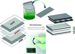
The PCFP (PVDF–CF–PVDF) sandwich structure was prepared by making two thin films of PVDF embedded with iron particles deposited CF mat. Additionally, a thin film of PVDF–MWNT composite was also prepared as inner layers. For this a composite containing 3 wt% of MWNTs in PVDF was melt mixed at 220 °C, 60 rpm and 20 min. Finally, the as prepared PVDF–MWNT composite film was sandwiched between two PFe@CFP layers to design the multilayered sandwich structure using a hot press as shown in Fig. 2. The thickness of the sandwich structure (PFe@CFP–PVDF/MWNT–PFe@CFP) is only 0.6 mm and is quite flexible as shown in Fig. 2.
image file: c6ra14154d-f2.tif
Fig. 2 Schematic showing the fabrication of PCFP/PVDF–MWNT/PCFP sandwich structure.

Characterization

The morphology of electroless deposited carbon fiber was studied using field emission scanning electron microscopy (SEM) (ULTRA 55, FESEM, Carl Zeiss). Energy dispersive X-ray technique attached with an ESEM (Quanta 200, FEI) was used to collect the spectra. Raman analysis was done using a Horiba LabRAM HR with a 532 nm monochromatic laser. EMI shielding of thin sample (ca. 0.6 mm) was measured using a Anritsu MS4642A two port Vector Network Analyser coupled to a Keycom waveguide to measure the scattering parameters in the frequency range of 12–18 GHz. Thin samples for EMI measurement were prepared by hot press.

Results and discussion

The electroless deposition of iron particles on CF mat was confirmed by scanning electron microscopy. Fig. 3a shows the morphology of bare carbon fibers. The electroless deposited iron particle onto CF mat is shown in Fig. 3b. The presence of iron particles was confirmed using EDS technique as shown in Fig. 3c.
image file: c6ra14154d-f3.tif
Fig. 3 (a) SEM morphology of bare CF mat; (b) iron particles decorated CF mat. (c) EDAX spectra of electroless deposited CF mat.

Raman analysis can reveal the structural integrity of CF. Fig. 4 shows the Raman spectra of CF and Fe@CF. Two signature peaks at 1355 and 1582 cm−1 corresponding to the D and G band respectively are well evident.22 D band corresponds to the disordered structure and G band corresponds to the ordered graphitic structure. Thus the ratio of ID/IG manifests the crystalline nature of C materials.22 The ID/IG ratio of the different CF is estimated to be ca. 1.07 for both the types of CF. It is interesting to note that the ratio is unaltered manifesting in the fact that electroless deposition is rather less harsh technique which helps in preserving the integrity of the CF unlike other techniques like electro-deposition, chemical routes etc.


image file: c6ra14154d-f4.tif
Fig. 4 Raman spectra of CF and Fe@CF.

The EMI shielding effectiveness (SE) of a material is defined as the ratio of incoming power (Pin) to the transmitted power (Pout). The EMI SE of a composite material depends on many factors such as electrical conductivity, magnetic permeability, size, shape and aspect ratio of filler.23 The higher value of SE means the total incoming radiations have been attenuated by the material. The SE was obtained from the scattering parameters measured using a VNA coupled to a waveguide set-up (see Fig. 5a). Fig. 5b illustrates the shielding effectiveness of various sandwich structures, where a single layer of control PCFP shows almost similar SE as compared to two layers of PCFP. Since the bare carbon fibers are electrically conducting and embedded within two insulating PVDF films which are transparent to EM radiations, the observed attenuation could be achieved partially by reflection mechanism and the impedance mismatch between two different medium. Surprisingly, the PVDF–MWNT composite film sandwiched between two PCFP layers also showed almost unaltered SE as compared to control PCFP because of extensive surface reflection governed by the outer layers. The total SE is controlled only by the outer layers and the effect of inner layer is almost masked. Similarly, single layer of PFe@CFP showed unaltered SE at lower frequencies however at higher frequencies a slight increment was observed. On the other hand, two (outer) layers of iron nanoparticles deposited CF (PFe@CFP) sandwiched with one (inner) layer of PVDF–MWNTs composite film showed significantly higher SE of −54 dB at 18 GHz. The dramatic increase in SE for the designed architecture (PFe@CFP–PVDF/MWNT–PFe@CFP) is attributed to the presence of magnetically active iron particle on to CF mat. We have demonstrated that PVDF/MWNTs showed better shielding effectiveness due to the presence of electrically conducting MWNTs.3b It is envisaged that the incident radiations could be utilized in aligning the magnetic domains and hence leading to magnetic loss. The radiation that penetrates these outer layers will be reflected back from the inner conductive layers (due to the presence of nomadic charge carriers in PVDF/MWNT composite films) and eventually will be scavenged by the outer layers. Thus, a synergistic effect can be expected from these architectures due to associated electric and magnetic dipole in the sandwich architecture that interacts with the EM waves.


image file: c6ra14154d-f5.tif
Fig. 5 (a) Set-up of Vector Network Analyzer coupled to a waveguide (b) SE of different sandwich structure as a function of frequency (PCFP 1 layer indicate that a CF mat is sandwiched between two PVDF films; PCFP 2 layers indicate that a PVDF/MWNT inner layer is sandwiched between two PCFP outer layers; PFe@CFP 1 layer indicate that Fe@CF mat is sandwiched between two PVDF films; PFe@CFP 2 layers indicate that a PVDF/MWNT composite film is sandwiched between two PFe@CFP outer layers).

It is important to tailor the properties of material in order to make it useful for a particular application. In this regard, it is possible to modify the surface of CF to make them applicable for EMI shielding application. The decoration of CF with iron particle has contributed significantly in attenuating the incoming EM radiation mostly by absorption. It is believed that the additional contribution in shielding mechanism could be due to the interfacial polarization created between CF and the attached magnetic nanoparticles. The inter linkages of CF resulting in conducting pathways when stacked in layer helps in absorbing the radiations.24 Additionally, the presence of magnetic particles leads to enhancement in absorption mechanism as compared to neat CF.24 As shown in Fig. 6a and b the reflection and absorption components of different composites were evaluated from the scattering parameters. It is interesting to see that our sandwich structures attenuate the incoming EM radiation mostly by absorption and the maximum absorption (>95%) is observed in PFe@CFP–PVDF/MWNT–PFe@CFP structure. This begins to suggest that the outer layers are less reflecting and more absorbing the incoming EM radiation due to the presence of magnetic particles on the CF mat. In addition, the interface between the layers also helps in multiple scattering due to heterogeneous dielectrics. When interacting with the incoming EM radiation the CF mat behave like a waveguide when they are cross linked and their absorption characteristics strongly depend on the geometric parameters (see Fig. 7). The waves that transmit the outer layers then interact with the inner layers consisting of PVDF/MWNT composite films. In Fig. 7, an equivalent circuit of MWNTs embedded in an insulating polymer is shown where it explains the interaction of these nano entities with EM signals by interconnection between capacitance and resistance. The inter-cluster polarization creates a virtual connection between the MWNTs leads to charge transport which is further explained by enhancement in increased conductivity of the composite.25 Our sandwich structure clearly demonstrates promising microwave absorbing materials.


image file: c6ra14154d-f6.tif
Fig. 6 (a) Reflection and (b) absorption components of total shielding effectiveness of different composites.

image file: c6ra14154d-f7.tif
Fig. 7 Schematic explaining the shielding mechanism.

Conclusions

Our study demonstrates the potential of multilayered architecture, consisting of PVDF and iron particles deposited on to CF mat by electroless deposition technique, in blocking EM radiation. The iron particles were deposited onto CF mat via single step activation process. The rational construction of two (outer) layers of PFe@CFP sandwiched between one (inner) layer of PVDF/MWNT composite showed a significant improvement is SE (ca. −54 dB) at 0.6 mm stack thickness as compared to control sandwich structures. The designed multilayered architecture is lightweight, flexible and easy to assemble; making them potential candidates as EM shielding materials. Such architectures can further be explored for various applications that require blocking of EM microwave radiation.

Acknowledgements

The authors would like to thank DST and INSA for the financial support and also Dr Jafar Hasan for his assistance in SEM imaging.

References

  1. (a) N. Li, Y. Huang, F. Du, X. He, X. Lin, H. Gao, Y. Ma, F. Li, Y. Chen and P. C. Eklund, Electromagnetic Interference (EMI) Shielding of Single-Walled Carbon Nanotube Epoxy Composites, Nano Lett., 2006, 6(6), 1141–1145 CrossRef CAS PubMed; (b) Y. Huang, N. Li, Y. Ma, F. Du, F. Li, X. He, X. Lin, H. Gao and Y. Chen, The influence of single-walled carbon nanotube structure on the electromagnetic interference shielding efficiency of its epoxy composites, Carbon, 2007, 45(8), 1614–1621 CrossRef CAS; (c) D. D. L. Chung, Electromagnetic interference shielding effectiveness of carbon materials, Carbon, 2001, 39(2), 279–285 CrossRef CAS.
  2. Z. Liu, G. Bai, Y. Huang, Y. Ma, F. Du, F. Li, T. Guo and Y. Chen, Reflection and absorption contributions to the electromagnetic interference shielding of single-walled carbon nanotube/polyurethane composites, Carbon, 2007, 45(4), 821–827 CrossRef CAS.
  3. (a) V. Bhingardive, S. Suwas and S. Bose, New physical insights into the electromagnetic shielding efficiency in PVDF nanocomposites containing multiwall carbon nanotubes and magnetic nanoparticles, RSC Adv., 2015, 5(97), 79463–79472 RSC; (b) V. Bhingardive, M. Sharma, S. Suwas, G. Madras and S. Bose, Polyvinylidene fluoride based lightweight and corrosion resistant electromagnetic shielding materials, RSC Adv., 2015, 5(45), 35909–35916 RSC.
  4. (a) L. Zou, S. Zhang, X. Li, C. Lan, Y. Qiu and Y. Ma, Step-by-Step Strategy for Constructing Multilayer Structured Coatings toward High-Efficiency Electromagnetic Interference Shielding, Adv. Mater. Interfaces, 2016, 3(5), 1500476 CrossRef; (b) H. S. Kim, B. H. Sohn, W. Lee, J. K. Lee, S. J. Choi and S. J. Kwon, Multifunctional layer-by-layer self-assembly of conducting polymers and magnetic nanoparticles, Thin Solid Films, 2002, 419(1–2), 173–177 CrossRef CAS.
  5. (a) L. L. Sun, B. Li, Y. Zhao, G. Mitchell and W. H. Zhong, Structure-induced high dielectric constant and low loss of CNF/PVDF composites with heterogeneous CNF distribution, Nanotechnology, 2010, 21(30), 305702 CrossRef CAS PubMed; (b) M. Sharma, M. P. Singh, C. Srivastava, G. Madras and S. Bose, Poly(vinylidene fluoride)-Based Flexible and Lightweight Materials for Attenuating Microwave Radiations, ACS Appl. Mater. Interfaces, 2014, 6(23), 21151–21160 CrossRef CAS PubMed.
  6. H. Gargama, A. K. Thakur and S. K. Chaturvedi, Polyvinylidene fluoride/nanocrystalline iron composite materials for EMI shielding and absorption applications, J. Alloys Compd., 2016, 654, 209–215 CrossRef CAS.
  7. T.-I. Yang and P. Kofinas, Dielectric properties of polymer nanoparticle composites, Polymer, 2007, 48(3), 791–798 CrossRef CAS.
  8. (a) W.-L. Song, M.-S. Cao, M.-M. Lu, S. Bi, C.-Y. Wang, J. Liu, J. Yuan and L.-Z. Fan, Flexible graphene/polymer composite films in sandwich structures for effective electromagnetic interference shielding, Carbon, 2014, 66, 67–76 CrossRef CAS; (b) J.-H. Lin, Z.-I. Lin, Y.-J. Pan, C.-L. Huang, C.-K. Chen and C.-W. Lou, Polymer composites made of multi-walled carbon nanotubes and graphene nano-sheets: effects of sandwich structures on their electromagnetic interference shielding effectiveness, Composites, Part B, 2016, 89, 424–431 CrossRef CAS.
  9. X. Shui and D. Chung, Nickel filament polymer-matrix composites with low surface impedance and high electromagnetic interference shielding effectiveness, J. Electron. Mater., 1997, 26(8), 928–934 CrossRef CAS.
  10. S. Geetha, K. Satheesh Kumar, C. R. Rao, M. Vijayan and D. Trivedi, EMI shielding: methods and materials—a review, J. Appl. Polym. Sci., 2009, 112(4), 2073–2086 CrossRef CAS.
  11. Y. Fan, H. Yang, H. Zhu, X. Liu, M. Li, Y. Qu, N. Yang and G. Zou, Metallization of Carbon Fibers with Nickel by Electroless Plating Technique, Metall. Mater. Trans. A, 2007, 38(9), 2148–2152 CrossRef.
  12. W.-L. Song, J. Wang, L.-Z. Fan, Y. Li, C.-Y. Wang and M.-S. Cao, Interfacial Engineering of Carbon Nanofiber–Graphene–Carbon Nanofiber Heterojunctions in Flexible Lightweight Electromagnetic Shielding Networks, ACS Appl. Mater. Interfaces, 2014, 6(13), 10516–10523 CAS.
  13. C.-Y. Huang and J.-F. Pai, Optimum conditions of electroless nickel plating on carbon fibres for EMI shielding effectiveness of ENCF/ABS composites, Eur. Polym. J., 1998, 34(2), 261–267 CrossRef CAS.
  14. S.-S. Tzeng and F.-Y. Chang, EMI shielding effectiveness of metal-coated carbon fiber-reinforced ABS composites, Mater. Sci. Eng., A, 2001, 302(2), 258–267 CrossRef.
  15. C.-Y. Huang and C.-C. Wu, The EMI shielding effectiveness of PC/ABS/nickel-coated-carbon-fibre composites, Eur. Polym. J., 2000, 36(12), 2729–2737 CrossRef CAS.
  16. S. Yang, K. Lozano, A. Lomeli, H. D. Foltz and R. Jones, Electromagnetic interference shielding effectiveness of carbon nanofiber/LCP composites, Composites, Part A, 2005, 36(5), 691–697 CrossRef.
  17. G. Lu, X. Li and H. Jiang, Electrical and shielding properties of ABS resin filled with nickel-coated carbon fibers, Compos. Sci. Technol., 1996, 56(2), 193–200 CrossRef CAS.
  18. A. Ameli, P. U. Jung and C. B. Park, Electrical properties and electromagnetic interference shielding effectiveness of polypropylene/carbon fiber composite foams, Carbon, 2013, 60, 379–391 CrossRef CAS.
  19. M. H. Al-Saleh, W. H. Saadeh and U. Sundararaj, EMI shielding effectiveness of carbon based nanostructured polymeric materials: a comparative study, Carbon, 2013, 60, 146–156 CrossRef CAS.
  20. S.-S. Hwang, Tensile, electrical conductivity and EMI shielding properties of solid and foamed PBT/carbon fiber composites. Composites, Part B, 2016, 98, 1–8 Search PubMed.
  21. L.-M. Ang, T. S. A. Hor, G.-Q. Xu, C.-H. Tung, S. Zhao and J. L. S. Wang, Electroless Plating of Metals onto Carbon Nanotubes Activated by a Single-Step Activation Method, Chem. Mater., 1999, 11(8), 2115–2118 CrossRef CAS.
  22. L. B. Nohara, G. Petraconi Filho, E. L. Nohara, M. U. Kleinke and M. C. Rezende, Evaluation of carbon fiber surface treated by chemical and cold plasma processes, Mater. Res., 2005, 8, 281–286 CrossRef.
  23. Y. Yang, M. C. Gupta, K. L. Dudley and R. W. Lawrence, Novel Carbon Nanotube–Polystyrene Foam Composites for Electromagnetic Interference Shielding, Nano Lett., 2005, 5(11), 2131–2134 CrossRef CAS PubMed.
  24. F. Qin and C. Brosseau, A review and analysis of microwave absorption in polymer composites filled with carbonaceous particles, J. Appl. Phys., 2012, 111(6), 061301 CrossRef.
  25. J.-M. Thomassin, C. Jérôme, T. Pardoen, C. Bailly, I. Huynen and C. Detrembleur, Polymer/carbon based composites as electromagnetic interference (EMI) shielding materials, Mater. Sci. Eng., R, 2013, 74(7), 211–232 CrossRef.

This journal is © The Royal Society of Chemistry 2016