DOI:
10.1039/C6RA14099H
(Paper)
RSC Adv., 2016,
6, 67839-67848
Mesoporous NiCo2O4 nanospheres with a high specific surface area as electrode materials for high-performance supercapacitors†
Received
1st June 2016
, Accepted 7th July 2016
First published on 7th July 2016
Abstract
Ternary nickel cobaltite (NiCo2O4) has attracted more and more attention as a promising electrode material for high performance supercapacitors (SCs) due to its high theoretical capacity, unique crystal structure and excellent electronic conductivity. In this study, a template-free chemical co-precipitation method as a general strategy has been easily developed to fabricate mesoporous NiCo2O4 nanospheres with a high specific surface area of 216 m2 g−1, which can be further self-assembled into 3D frameworks. The key to the formation of mesoporous NiCo2O4 nanospheres with a desired pore-size distribution centered at ∼2.4 nm is a unique preparation method assisted with sodium bicarbonate as a complex agent. When tested as electrode materials for SCs, the NiCo2O4 electrodes delivered excellent electrochemical performances with high specific capacitance (842 F g−1 at a current density of 2 A g−1), superior cycling stability with no capacity decrease after 5000 cycles (103% initial capacity retention), and great rate performance at a 10-time current density increase (79.9% specific capacitance retention). Furthermore, as expected in a NiCo2O4-based asymmetric supercapacitor device, a superior energy density as high as 29.8 W h kg−1 at a power density of 159.4 W kg−1 could be achieved. These results highlight a general, eco-friendly, template-free strategy for the scale-up fabrication of a promising mesoporous NiCo2O4 electrode material for high-performance SC applications.
1. Introduction
As one of the most promising clean energy storage system, electrochemical supercapacitors (SCs) have stimulated great research interest in the field of energy storage by virtue of their inherent significant advantages over conventional storage devices, such as short charging–discharging time, outstanding power density, and long lifespan.1,2 However, low energy density greatly limits their application as a primary power source in many important fields. How to enhance their energy density without sacrificing their high-power density and cycle life is a critical challenge for SCs development. In order to improve the energy density of supercapacitors, great efforts have been made by many researchers in recent years. Referring to the equation of energy density (E = 1/2CV2), the energy density of SCs can be greatly improved by enhancing the cell voltage (V) and/or the device specific capacitance (C).3 Clearly, one effective approach to enhance the work voltage windows of SCs in aqueous electrolyte is to design and construct asymmetric supercapacitors (ASCs)4 by combining of two different electrodes (one is electric double-layer capacitive electrode and the other is pseudocapacitive electrode). The ASCs can combine the potential windows of the two different electrodes to increase the maximum operation potential window in the cell, leading to the significantly enhanced energy density.5
Another effective way involves the development of high-capacity materials and the design of the tailored architecture, which can be used to promote supercapacitor performance.6,7 Therefore, diverse transition metal oxides (CoxOy,8,9 NiO,10 MnO2,11 RuO2,12 and et al.) have been widely investigated as promising alternative pseudocapacitance electrode materials in the ASCs due to their high theoretical specific capacitance (in the order of magnitude of 1000 to 4000 F g−1). However, these single materials usually suffer from poor intrinsic conductivity, resulting in low practical capacitance and undesirable energy density. Thus, most of researchers load these materials on carbon materials with higher electrical conductivity, such as carbon nanotubes, carbon fibers, graphene, and graphene aerogels, to enhance the electronic conductivity. However, the achievement of these composite materials often requires complex or accurate control of the synthesis process.13 To effectively avoid this critical problem, binary composites of metal oxides such as Ni–Co, Co–Mo, Co–Ru oxides have become the emphasis of pseudocapacitors study because their plentiful structure defects are beneficial for large electrode/electrolyte contact surface and fast redox reactions. Among them, nickel cobaltite (NiCo2O4), which possesses a much better electronic conductivity (at least 2 orders of magnitude higher than single nickel oxide or cobalt oxide14) is of particular interest. Moreover, its high electrochemical activity can further favour the enhancement of capacitance due to two different ions in the spinel NiCo2O4 crystal structure can offer richer redox reactions compared with single-component oxides.15 In view of these unique features of spinel NiCo2O4 electrodes, they have been demonstrated as the most promising pseudocapacitance electrodes in the field of SCs and drawn growing attention for electrochemical energy storage.
Up to now, diverse spinel NiCo2O4 nanostructures employed as an electrode material for SCs have been usually synthesized by using the hydrothermal method16 and the solvothermal method.17 At the same time, many other methods, such as the sol–gel method, electro-deposition process and microwave technique, have also successfully been conducted to fabricate NiCo2O4 nanomaterials, and all of these major methods are distinctive. However, despite these efforts in the fabrication of various NiCo2O4-based nanostructures, the methods used are relatively time-consuming, complicated procedures, high cost (high reaction temperatures) and a small area of production, which restrict their applications. More important, the promising NiCo2O4-based nanomaterials for electrode materials with desired mesoporous nanostructures, high surface area, and tunable 3D structure still remain a challenge.
In this study, we have developed a cost-effective method, namely template-free sodium bicarbonate-assisted chemical co-precipitation method followed by a post annealing treatment, to fabricate original mesoporous NiCo2O4 nanospheres. These nanospheres with high specific surface area (216 m2 g−1) can further self-assemble into 3D cross-linked complex framework, which alleviates the volume change during the charge–discharge process. As expected, in comparison with the reported NiCo2O4 nanostructure electrodes, the developed mesoporous NiCo2O4 nanospheres exhibit a high reversible capacities of 842 F g−1 at the current density of 2 A g−1, and the capacitance remains as high as 79.9% when the current density increases to 20 A g−1. The electrode also exhibits robust long term cycling performance with 103% initial capacity retention after 5000 cycles. Furthermore, superior energy density of 29.8 W h kg−1 can be achieved in the prepared ASCs by using the NiCo2O4 electrode as the positive and activated carbon as negative electrodes, respectively. The fabrication method presented in this study is proved to be facile, cost-effective and large scalable, and it may open a new pathway for real SCs device applications.
2. Experimental
2.1 Synthesis of NiCo2O4 nanospheres
All the used raw chemical reagents were of analytical grade without further purification. The typical synthetic route was as follows: solution A: 0.374 g of cobalt acetate (Co(Ac)2) and 0.291 g of nickel nitrate (Ni(NO3)2) were successively dissolved in 25 mL of distilled water and continuously stirred for 2 h. Solution B: 0.5 g of sodium bicarbonate (NaHCO3) was dissolved in 20 mL of distilled water to get a transparent solution under stirring for 2 h. A pink suspension solution can slowly form when solution B was sequentially drop by drop added to the solution A. The mixed solution was stirred for another 12 h at room temperature, and then the products were obtained by centrifugation and washed with absolute ethanol for several times and dried in vacuum at 60 °C over-night. The final products of NiCo2O4 were obtained after annealed the precursor at 250 °C for 3 h in air. The schematic illustration of the synthesis of NiCoO4 nanospheres is shown in Fig. 1. The production efficiencies of NiCo2O4 nanoparticles were >90%. In this study, the method for fabricating NiCo2O4 involved a three simple step process as described by the following reactions:18
| HCO3− + H2O ↔ H2CO3 + OH− |
| Ni2+ + 2Co2+ + 6OH− → NiCo2(OH)6 |
 |
| | Fig. 1 Schematic illustration of the synthesis of NiCo2O4 nanospheres. | |
After the followed calcination process, the resulting NiCo2(OH)6 precursors can be converted into the final oxide products of spinel NiCo2O4 via dehydration reaction.
2.2 Material characterization
The scanning electron microscopic (SEM) images of the materials were obtained by a field-emission scanning electron microscope (SU8020, HITACHI). Transmission electron microscopy (TEM) micrographs were obtained from an FEI Tecnai G2 S-twin transmission electron microscope with a field emission gun operating at 200 kV. Chemical compositions and crystallite structures of the samples were determined by XRD (Rigaku D/max-2550, Japan) using Cu Kα radiation from 10 to 80 angles. Nitrogen (N2) adsorption–desorption isotherm measurements were performed on a Micromeritics ASAP 2020 volumetric adsorption analyzer at 77 K. Before adsorption–desorption isotherm measurements, the samples were outgassed at 80 °C for 10 h in the degas port of the analyzer. The X-ray photoelectron spectra (XPS) were recorded on a VG ESCALAB MK II electron spectrometer. Inductively coupled plasma optical emission spectrometer (Thermo SCIENTIFIC ICAP 7000 SERIES) was used to analyze the actual composition of NiCo2O4 nanospheres.
2.3 Electrochemical measurements
The SC electrodes were prepared by mixing the as-prepared NiCo2O4 powders, acetylene black and polytetrafluoroethylene emulsion (PTFE) with a weight ratio of 8![[thin space (1/6-em)]](https://www.rsc.org/images/entities/char_2009.gif) :1:1. Then, a few drops of deionized water were added to form the thick slurry. Subsequently, the resultant slurry was homogeneously pasted onto a porous Ni foam sheet (1 cm × 1 cm), followed by pressed under a pressure of 10 MPa and dried at 75 °C for 24 h.
:1:1. Then, a few drops of deionized water were added to form the thick slurry. Subsequently, the resultant slurry was homogeneously pasted onto a porous Ni foam sheet (1 cm × 1 cm), followed by pressed under a pressure of 10 MPa and dried at 75 °C for 24 h.
For the three-electrode measurements, the as-prepared NiCo2O4 single electrode was directly used as working electrode (WE), a platinum electrode as counter electrode (CE) and a saturated calomel electrode (SCE) as reference electrode (RE). The electrochemical performances were evaluated by cyclic voltammetry, galvanostatic charge–discharge technique and electrochemical impedance spectroscopy using an electrochemical workstation (IVIUMSTAT; Ivium Technologies, Netherlands). All the tests were carried out at room temperature in a 6 M KOH aqueous solution. According to the three-electrode data, the specific capacitance of the single electrode material can be calculated from the cyclic voltammetry curves and discharge curves with the eqn (1) and (2), respectively.19
| |
 | (1) |
where (F g
−1) is the specific capacitance,
v (mV s
−1) is the potential scan rate,
i(
u) (A) is the voltammetric current, Δ
V (V) is the potential drop during discharge,
I (A) is charge–discharge current, Δ
t (s) is the discharge time,
m (g) represents the mass of the active material. The loading mass of active material was ∼2.0 mg cm
−2.
Moreover, asymmetric capacitors was fabricated by assembling with the NiCo2O4 electrodes as anode and the activated carbon (AC) electrodes as cathode separated by a porous non-woven cloth in a CR2032-type coin cell. The optimal mass ratio of m(NiCo2O4)/m(AC) should be about 0.59 in the ASCs, which is based on charge balance theory and their respective specific capacitances.20,21 The specific capacitance can be calculated out from the two-electrode data by using the eqn (2), except that represents the overall mass of the positive and negative electrodes. The energy density (E) in W h kg−1 and power density (P) in W kg−1 derived from galvanostatic charge discharge curves can be calculated out by the following expressions:22
where
Cs is the specific capacitance of the ASCs, Δ
t is the discharging time and Δ
V is the voltage change during the discharging time after
IR drop.
3. Results and discussion
3.1 Structure and morphology characterizations of NiCo2O4 nanospheres
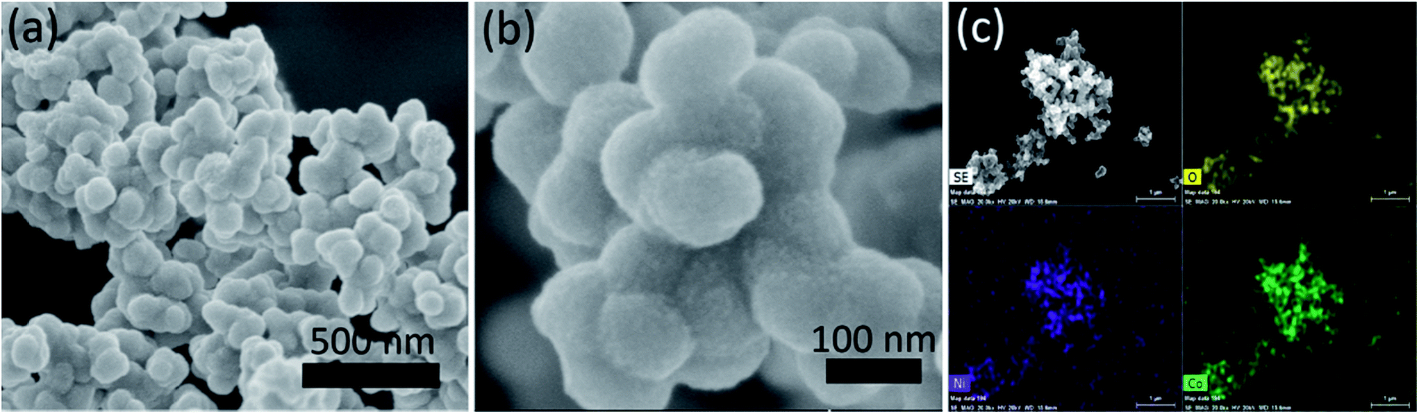
SEM characterizations were first used to investigate the microstructure of as-prepared mesoporous NiCo2O4 nanospheres. As shown in Fig. 2a and b, NiCo2O4 nanospheres are irregularly self-assembled into complex nanostructures with the diameters varying from several tens of nanometers to several hundreds of nanometers in the low-magnification SEM images. In fact, each NiCo2O4 sphere is composed of numerous tiny NiCo2O4 nanoparticles in the high-magnification SEM images (Fig. 2b). Moreover, these cross-linked nanoparticles form a relatively loose packed structure with abundant and porous, which absolutely increases the effective liquid solid interfacial area, provides a fast path for the insertion and extraction of electrolyte ions, and consequently facilitates the Faraday reaction.9 At the same time, the self-assembled 3D framework can also be benefit for developing the electronic conductivity, providing efficient electron transport and leading to greatly improved electrochemical performance. Fig. 2c displays the representative SEM image of the NiCo2O4 nanospheres and the corresponding elemental mapping of O, Ni and Co, indicating the uniform distribution of nickel, cobalt and oxygen element in the NiCo2O4 nanospheres.
 |
| | Fig. 2 (a and b) Typical low- and high-magnification SEM images of NiCo2O4 nanospheres (c) a representative SEM image of NiCo2O4 nanospheres and its corresponding elemental mapping of O, Co and Ni. | |
The X-ray diffraction pattern (Fig. 3a) reveals the phase purity and crystalline structure of the as-prepared cubic spinel NiCo2O4 nanospheres. The diffraction peaks are observed at 2θ = 18.9°, 31.1°, 36.69°, 44.62°, 59.09° and 64.98°, which can be assigned to the (111), (220), (311), (400), (511) and (440) planes of cubic spinel NiCo2O4 phase (JCPDS 20-0781; space group: F*3 (202)).1 No secondary phases can be detected in the XRD pattern. For confirming the bulk chemical compositions, the obtained products were further dissolved by concentrated hydrochloric acid and characterized by ICP. Results show that the atom ratio between nickel and cobalt of products was 1:1.96, which is in agreement with the chemical formula. Hence, the sample is constituted by NiCo2O4 according to the experimental data obtained from XRD and ICP. The mesoporous characteristics of as-prepared NiCo2O4 are further studied by nitrogen adsorption and desorption measurement, as presented in Fig. 3b. From the adsorption–desorption isotherm, a typical IV adsorption–desorption isotherms with well-defined H4-type hysteresis loop at relative pressure ranged in 0.6–1.0 P/P0 can be observed, indicating that the well-formed mesoporous structure.23 The Brunauer–Emmett–Teller (BET) surface area and pore volume of the NiCo2O4 nanospheres are calculated to be 216 m2 g−1 and 0.154 cm3 g−1, respectively. Moreover, the inset of Fig. 3b shows the corresponding pore size distribution curve of NiCo2O4 nanospheres derived from the adsorption branch by the Barrett–Joyner–Halenda (BJH) method. The curve reveals that the pore size distribution is uniform within the range of mesopores. Notably, the size of the majority of mesopores falls in about 2.4 nm, which is the ideal pore size for the diffusion of ions and electrons within the electrode.24 With the unique features of large specific surface area and mesoporous structure, which may be mainly caused by many tiny nanoparticles self-accumulation in the chemical synthesis process25 and the release of gases during the thermal decomposition process,26 the NiCo2O4 nanospheres can be regarded as a promising candidate electrode material for SCs, since the abundant internal porous structure with suitable pore size can not only increase the electrode/electrolyte contact area but also shorten the diffusion distance to the interior surfaces so that the sufficient redox reactions can take place at high current densities for SC energy storage.9
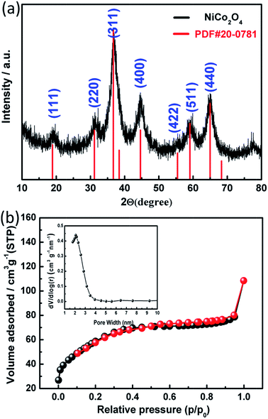 |
| | Fig. 3 (a) XRD pattern of the NiCo2O4 nanospheres. (b) N2 adsorption–desorption isotherm of NiCo2O4 nanospheres. The inset in (b) is the corresponding pore size distribution curve. | |
Further characterization of the morphology and structure of the mesoporous NiCo2O4 nanospheres was carried out by using TEM. The TEM image at a low magnification in Fig. 4a demonstrates that the mesoporous nanospheres with rich pore are assembled with numerous small cross-linked nanoparticles with an average diameter of 5 ± 2 nm, consisting with the SEM results. Furthermore, uniformly distributed mesopores between the adjacent nanoparticles can be unequivocally observed from Fig. S1 (ESI†), and the porous characteristics can further increase the amount of electro-active sites and facilitate the electrolyte penetration.2 The size of the mesopores of the nanospheres is estimated to be in the range of 2–5 nm, which is consistent with the adsorption–desorption isotherm study. The selected area electron diffraction (SAED) pattern (Fig. 4b) further confirms the polycrystalline nature of the NiCo2O4. The concentric diffraction rings, from inside to out, can be assigned to the (220), (311), (422) and (440) planes of NiCo2O4, respectively. Additionally, the high-resolution TEM (HRTEM) images of NiCo2O4 display in Fig. 4c and d, and the unambiguous lattice fringe image indicates that the NiCo2O4 nanoparticles are of single crystal character. The distinct lattice fringe spacing of 0.2448 nm corresponds to the (311) plane spacing of NiCo2O4. The lattice spacing of d ∼ 0.203 nm in Fig. 4d closes to that of 2.029 Å (400),27 given in the JCPDS card 20-0781 file. These results coincides well with the XRD data.
 |
| | Fig. 4 (a) Low-magnification TEM image, (b) the corresponding SAED patterns, (c) and (d) high-magnification TEM images of the NiCo2O4 nanospheres. | |
To obtain more detailed information about elemental surface composition, content, and surface chemical state of as-prepared NiCo2O4 nanospheres, X-ray photoelectron spectroscopy (XPS) measurements were performed and the corresponding results were presented in Fig. 5. As shown in Fig. 5a, the XPS signals of elements Ni 2p, Co 2p and O 1s can be observed in the XPS survey spectrum, demonstrating the existence of nickel, oxygen, and cobalt elements in the sample, consistent with the results obtained by elemental mapping in Fig. 2c. By using a Lorentzian–Gaussian fitting method, the Ni 2p spectrum (Fig. 5b) exhibits two spin–orbit doublets, which are characteristic of Ni2+ and Ni3+, and two shakeup satellites (identified as “Sat.”). Similarly, the Co 2p spectrum (Fig. 5c) are also composed of two spin–orbit doublets characteristic of Co2+ and Co3+ and two shakeup satellites.28 These results demonstrate that these chemical elements on the surface of as-prepared NiCo2O4 nanospheres have rich valence states including Co2+, Co3+, Ni2+ and Ni3+, which are in good agreement with previous reports.18,26 The detailed binding energies indexed to the corresponding different peaks are presented in Table 1. Moreover, Fig. 5d gives the XPS spectrum of the O 1s from NiCo2O4 composites. The peaks at binding energies of 529.47, 530.5, 531.3, and 532.1 eV can be identified as O1, O2, O3, and O4, respectively. The component O1 is typical of the metal–oxygen bond. The component O2 corresponds to oxygen in hydroxyl groups on the surface of NiCo2O4.29 The O3 and O4 components can be commonly associated with the defect sites with low oxygen coordination in the material with small particle size, and the multiplicity of physi/chemisorbed water,30,31 respectively.
 |
| | Fig. 5 (a) Survey and high-resolution XPS spectra of (b) Ni 2p, (c) Co 2p, and (d) O 1s of NiCo2O4 nanospheres. | |
Table 1 The detailed binding energies indexed to the corresponding XPS peaks of NiCo2O4 nanospheres
| XPS spectra |
Ni 2p |
Co 2p |
O 1s |
| Ni2+ |
Ni3+ |
Sat. |
Co2+ |
Co3+ |
Sat. |
O1 |
O2 |
O3 |
O4 |
| B.E./eV |
873.3 |
871.2 |
879.7 |
796.6 |
794.9 |
803.83 |
529.47 |
530.5 |
531.3 |
532.1 |
| 855.8 |
854.7 |
861.2 |
781.2 |
779.7 |
786.28 |
3.2 The electrochemical characterizations of NiCo2O4 nanospheres
In order to evaluate the electrochemical performances of the as-fabricated NiCo2O4 electrodes, cyclic voltammetry (CV) at various scan rates within the electrochemical window from 0 to 0.4 V is carried out and the corresponding CV curves are appeared in Fig. 6a. Obviously, the shapes of CV curves are evidently different from the CV curve of typical double-layer capacitance (EDLC) with an ideal rectangular shape, indicating that the capacitance of NiCo2O4 electrodes are mainly originated from the pseudo-capacitance instead of EDLC in the alkaline electrolyte, which is due to the reversible redox reaction that happened between the NiCo2O4 electrode and the electrolyte. The possible redox reactions are based on following equations according to the literatures:32| | |
NiCo2O4 + H2O + OH− ↔ 2CoOOH + NiOOH + e−
| (5) |
| | |
CoOOH + OH− ↔ CoO2 + H2O + e−
| (6) |
 |
| | Fig. 6 (a) CV curves of NiCo2O4 electrode at different scan rates. (b) The charge–discharge curves of NiCo2O4 electrode at different current densities. (c) Variation of specific capacitance of NiCo2O4 at different discharge current densities. (d) The electrochemical impedance spectra of NiCo2O4 electrode before and after 5000 cycling tests. Inset: magnification of the high-frequency region of the impedance spectra and the electrical equivalent circuit used for fitting impedance spectra. | |
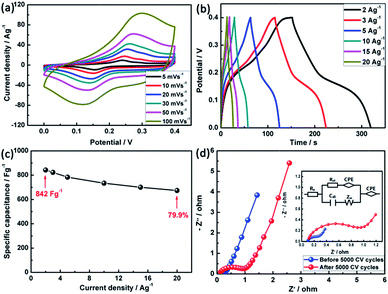
The two redox reactions can be confirmed by a pair of redox peaks at ∼0.25 and 0.15 V at the scan rate of 5 mV s−1 in Fig. 6a. It is noted that observing only a pair of redox peaks instead of two pairs can be attributed to the overlapped redox potentials peaks of Ni2+/Ni3+ and Co3+/Co4+ transitions due to the very close peak position between them.33 Interestingly, the redox current increases with increasing the scan rates from 5 to 100 mV s−1, suggesting that the interfacial kinetics and the rates of electronic and ionic transport are rapid enough in the applied scan rates.34 Also, the positions of oxidation and reduction peaks can shift to higher and lower potentials with the increase of scan rate, respectively, which can be attributed to the polarization effect of the electrode.35 To exclude the influence of nickel foam, the CV curves of bare Ni foam at a scan rate of 10 mV s−1 are conducted (Fig. S2, ESI†). It can be found that its CV curve area is very small, which suggests that the capacitance contribution from nickel foam can be neglected.36 According to eqn (1) mentioned above, the specific capacitance of NiCo2O4 determined by CV curves at 5 mV s−1 is about 634 F g−1, which is 1.1 fold higher than one with the 10 fold increase of the scan rate. The specific capacitance of NiCo2O4 electrodes can be decreased with increasing the scan rate duo to the electrolyte ions cannot be fully accessible to the interior surfaces of the electrodes with reduced diffusion time and only the outer active surface of the nanospheres can be utilized during charge storage process.
The galvanostatic charge–discharge (GCD) measurements were carried out at current densities from 2 to 20 A g−1, demonstrating symmetrical features between the charging and discharging branches for the NiCo2O4 electrodes (Fig. 6b), suggesting ideal pseudocapacitive nature of the charge–discharge process. All the GCD curves present a pair of charge and discharge plateaus at ∼0.25 and ∼0.15 V (vs. SCE) corresponding to the pseudo-capacitance characteristic, which are similar to the features obtained from the above CV curves. Furthermore, according to eqn (2), the specific capacitance of NiCo2O4 can be calculated to be 842, 823, 783, 734, 700 and 673 F g−1 at a current density of 2, 3, 5, 10, 15 and 20 A g−1, respectively. The decrease of capacitance with the increase of the charge–discharge current indicates that the inner active sites are unable to sustain the redox transition completely37 and the polarization phenomenon appears at higher current density.38 Fig. 6c depicts the summary plot of Cs vs. current density. 79.9% retention of the specific capacitance of the NiCo2O4 electrode at 20 A g−1 can be achieved when the measured current is increased from 2 to 20 A g−1, indicating that the NiCo2O4 exhibits good rate capability to use as electrode material for SCs.
Fig. 6d presents the Nyquist plots (imaginary part, −Z′′ versus real part, Z′) of NiCo2O4 electrode, which are recorded in the frequency range of 0.1–100 kHz at open circuit potential with a perturbation of 10 mV. The measured impedance spectra are analyzed and fitted by the software of IVIUMSTAT on the basis of the electrical equivalent circuit. The enlarged view of the high frequency region and the corresponding electrical equivalent circuit are displayed in the inset of Fig. 6d. In this equivalent circuit, different parameters indicate different electrochemical process occurring at the electrode/electrolyte interface. At very high frequency region, the intercept on the X-axis relates to the equivalent series resistance (ESR, Rs) including combined resistance of ionic resistance of electrolyte, intrinsic resistance of substrate and contact resistance at the active material/current collector.39 The diameter of the semicircle corresponds to the ionic charge transfer resistance (Rct) caused by faradic reactions and EDLC (Cdl).40 The Warburg resistance (ZW), the slope of the 45° portion of the Nyquist plots, is described as a diffusive resistance of the OH− ion within the NiCo2O4/Ni foam current collector and the CPE is the constant phase angle element relates to the ZW.41 Obviously, both the impedance spectra are almost similar in shape, being composed of one semicircle at high frequency followed by a spike at low frequency, with the exception of the small change of ionic charge transfer resistance. The Rs obtained by fitting the experimental results is 0.088 Ω, indicating the excellent conductivity of NiCo2O4 electrode. After 5000 cycles, Rct increasing from 0.241 to 0.927 Ω can be observed, which is attributed to the decomposition of the electrolyte and decrease of electrical conductivity continually.42
Long cycling life is another important requirement for SCs. In this context, the cycling life tests for the NiCo2O4 electrodes were carried out by repeating the CV test between 0 and 0.4 V at a scan rate of 30 mV s−1 for 5000 cycles, as shown in Fig. 7. It can be clearly observed that the capacitance retention of the NiCo2O4 electrode is 107% during the first 1000 cycles, which can be generally explained by the activation of the electrode materials. During the repeated CV process, as the electrolyte gradually penetrates into the inner region of the electrodes, more and more sites become activated and contribute to the increase of capacitance.43 After 5000 full cycles, the overall capacitance retention of the NiCo2O4 electrode is still as high as 103%, demonstrating the excellent long-term electrochemical stability. Given the fact that no obvious weight loss for the active electrode can be found after 5000 cycles, the improved electrochemical performance can be attributed to the following factors: (1) the NiCo2O4 framework with outstanding electrical conductivity benefits the electron transportation and electrolyte ion diffusion.44 (2) The NiCo2O4 nanospheres possess a large accessible surface area, which not only increases the material utilization, but also accommodates their volume change and allows effective strain relaxation upon cycling. (3) The existing satisfactory mesopores with pore size centered as ∼2.4 nm in the NiCo2O4 nanospheres can provide efficient transport pathways and ensure the effective contact between the electrode and electrolyte.45 All these features are benefit for high-rate capability and long-term cycling performance of SCs. In addition, the CV curves of the different cycles ranging from 1 to 5000 with an increment of 1000 cycles are shown in the inset of Fig. 7. It is clear that the enclosed area of the 1000th cycle is larger than that of the first cycle and the integrated CV areas of the NiCo2O4 electrode after 1000 cycles remain the same, indicating that there is an activation process of the electrode at the beginning period of the CV cycling test. Notably, a pair of new and strong redox peaks located at about 0.31 V and 0.17 V appears. The shifted peaks can be mainly caused by the eqn (6), because the redox reaction should be related to the Co(II)/Co(III) transitions in the low potential range. While preceding the oxygen evolution reaction at high potential, the Co(III)/Co(IV) transitions should predominate.46
 |
| | Fig. 7 The cycle performance of NiCo2O4 electrode at the scan rate of 30 mV s−1. Inset: the CV curves of the different cycles. | |
3.3 The electrochemical characterizations of NiCo2O4//activated carbon ASCs
To further evaluate the electrochemical performance of as-prepared NiCo2O4 materials, a series of ASC cells were constructed. In order to eliminate the damage of the cells resulted from high-voltage level during measurements, it is necessary to polarize the electrodes of the ASCs and thus estimate the reasonable electrochemical windows. The CV curves for the as-fabricated ASC devices with various potential windows from 0–1.4 to 0–1.8 V are provided in Fig. 8a. It is noted that within the narrow voltage of 0–1.4 V, no obvious oxidation and reduction peaks in the CV curves can be observed for ASCs. When sweeping the voltages from 1.5 to 1.6 V, the fabricated ASCs exhibit a typical capacitive behavior with distorted rectangular CV curves. However, when the voltage is larger than 1.7 V, a sharp polarization peak occurred in the CV curve together with dramatically increased current can be observed due to the electrolyte is being decomposed with hydrogen and/or oxygen evolution. Thus, to investigate the overall electrochemical performance, the optimum working potential window for NiCo2O4-based ASCs can be confirmed to be 0–1.6 V. The CV curves of the optimised NiCo2O4//AC asymmetric cell are displayed in Fig. 8b at different scan rates ranging from 5 to 100 mV s−1. The oxidation and reduction peaks from the CV curves can be observed, indicating a typical pseudocapacitive characteristic. In addition, there is no obvious distortion of the CV curves, even at a high scan rate, demonstrating the low resistance of the electrode and the ultrafast electronic and ionic transport rate between the NiCo2O4 electrode and KOH electrolyte,47 which can be further verified by the EIS measurement below. Fig. 8c presents the GCD curves of ASCs at different current densities from 0.2 to 2 A g−1, showing a typical triangular shape proportional to the charged or discharged times, indicating well balanced charge storage. Furthermore, the voltage drop (IR-drop) observed from the beginning of the discharge can be negligible suggesting a low ESR for the NiCo2O4-based ASCs.48 The rate performance, which directly depends on the attenuation of capacitance observed in GCD measurements, is reflected in Fig. 8d. The specific capacitance of the NiCo2O4-based ASCs is calculated to be 83.7 F g−1 at 0.2 A g−1 (2.88 mA cm−2) and 46.3 F g−1 at 2 A g−1, showing a good rate capability. The specific capacitance of ASC recovers to 81.6 F g−1 when the current density is set back to the initial 0.2 A g−1, further demonstrating its high reversibility.
 |
| | Fig. 8 (a) CV curves of the NiCo2O4//AC ASCs cell measured at different potential windows. (b) CV curves of the ASCs at different scan rates. (c) GCD curves of the ASCs at different current densities in 6 M KOH electrolyte. (d) Rate performance of the ASCs at different current densities. (e) Ragone plot related to energy and power densities of the ASCs. Inset: the digital photograph of CR2032-type coin cell. (f) The electrochemical impedance spectrum of NiCo2O4 electrode. Inset: magnification of the high-frequency region of the impedance spectrum and the electrical equivalent circuit used for fitting impedance spectrum. | |
The in-depth understanding of the electrochemical behavior of the NiCo2O4-based ASCs was conducted by the EIS measurements. As shown in Fig. 8e, the NiCo2O4-based ASCs exhibit a small semicircle diameter in the high-frequency region and a linear component at the low frequency. The intercept on the Z real axis (Rs) is measured to be 0.48 Ω and the corresponding Rct is calculated to be 2.04 Ω, indicating that the as-prepared NiCo2O4-based ASCs have a good distribution and connection of ions at the electrode/electrolyte interface due to the mobility of the OH− and the porous structure of the electrode materials. Thus, the lower charge-transfer resistance Rct of NiCo2O4-based ASCs can ensure to achieve a high power density.
To further illustrate the energy and power property of the NiCo2O4-based ASCs, Ragone plot was plotted based on charge–discharge data as shown in Fig. 8f. According to eqn (3) and (4) mentioned above, the maximum energy density of 29.8 W h kg−1 can be obtained at a power density of 159.4 W kg−1, while 16.5 W h kg−1 can be still maintained for the energy density even at a power density of 1648 W kg−1. The excellent electrochemical performance makes NiCo2O4 nanospheres one of the choices for a variety of emerging energy applications. Inset of Fig. 8f is the device (CR-2032) photographs with positive and negative electrode. Based on the above measurements, the NiCo2O4 nanospheres show excellent electrochemical performance, including good rate performance and high power/energy density, and it is superior to other electrode materials based on NiCo2O4 and its composite (Table S1, ESI†). The superior electrochemical performances for as-prepared ASCs can be deduced from the following aspects. First, 3D framework assembled with NiCo2O4 nanospheres can improve the electronic conductivity and decrease the resistance, which is beneficial for the fast transfer of electrons, thus enhancing the rate capability. Second, the large specific surface area can increase the electrode/electrolyte contact area and provide more efficient active sites, resulting in a greatly enhanced capacitance.49 Thirdly, the mesoporous structure of NiCo2O4 nanospheres with richer redox activity can deliver suitable pore volumes, in which more OH− in electrolyte can be stored and interface regions are enlarged.50,51
4. Conclusions
In summary, we have successfully synthesized mesoporous NiCo2O4 nanospheres framework by a simple template-free chemical co-precipitation method followed by a post annealing treatment, which exhibits a large specific surface area and porous characteristic. The as-obtained electrode possesses a high specific capacitance of 842 F g−1 at a current density of 2 A g−1. When cycling at high scan rate of 30 mV s−1 for 5000 cycles, the high capacitance retention of 103% is achieved. Moreover, the assembled NiCo2O4//AC ASCs delivers achieved the maximum specific capacitance of 83.7 F g−1 at 0.2 A g−1 with a stable operational voltage of 1.6 V, and a high energy density of 29.8 W h kg−1 at a power density of 159.4 W kg−1. These results clearly illustrate that mesoporous NiCo2O4 nanospheres are highly desirable as advanced electrode materials for supercapacitors.
Acknowledgements
This work was supported by the Natural Science Foundation of China (No. 11274138, 21571080, and 10604020), the Key projects of science and technology development plan of Jilin province (No. 20116007), the key projects of science and technology development plan of Changchun (No. 13KG13), International cooperation projects of science and technology of Changchun (No. 13GH10), the special program of international science and technology cooperation projects of China (No. 2014DFR61140).
References
- A. K. Mondal, D. W. Su, S. Q. Chen, K. Kretschmer, X. Q. Xie, H. J. Ahn and G. X. Wang, ChemPhysChem, 2015, 16, 169–175 CrossRef CAS PubMed.
- W. Xiong, Y. S. Gao, X. Wu, X. Hu, D. N. Lan, Y. Y. Chen, X. L. Pu, Y. Zeng, J. Su and Z. H. Zhu, ACS Appl. Mater. Interfaces, 2014, 6, 19416–19423 CAS.
- J. Xu, Q. F. Wang, X. W. Wang, Q. Y. Xiang, B. Hang, D. Chen and G. Z. Shen, ACS Nano, 2013, 7, 5453–5462 CrossRef CAS PubMed.
- Q. Q. Tang, M. M. Chen, L. Wang and G. C. Wang, J. Power Sources, 2015, 273, 654–662 CrossRef CAS.
- H. Peng, G. F. Ma, K. J. Sun, J. J. Mu, M. T. Luo and Z. Q. Lei, Electrochim. Acta, 2014, 147, 54–61 CrossRef CAS.
- Y. R. Zhu, Z. B. Wu, M. J. Jing, W. X. Song, H. S. Hou, X. M. Yang, Q. Y. Chen and X. B. Ji, Electrochim. Acta, 2014, 149, 144–151 CrossRef CAS.
- Y. H. Li, M. Zhou, X. Cui, Y. Yang, P. Xiao, L. J. Cao and Y. H. Zhang, Electrochim. Acta, 2015, 161, 137–143 CrossRef CAS.
- X. H. Xia, J. P. Tu, Y. Q. Zhang, Y. J. Mai, X. L. Wang, C. D. Gu and X. B. Zhao, RSC Adv., 2012, 2, 1835–1841 RSC.
- M. J. Pang, G. H. Long, S. Jiang, Y. Ji, W. Han, B. Wang, X. L. Liu, Y. L. Xi, D. X. Wang and F. Z. Xu, Chem. Eng. J., 2015, 280, 377–384 CrossRef CAS.
- F. Cao, G. X. Pan, X. H. Xia, P. S. Tang and H. F. Chen, J. Power Sources, 2014, 264, 161–167 CrossRef CAS.
- W. Yao, J. Wang, H. Li and Y. Lu, J. Power Sources, 2014, 247, 824–830 CrossRef CAS.
- Z. S. Wu, D. W. Wang, W. Ren, J. Zhao, G. Zhou, F. Li and H. M. Cheng, Adv. Funct. Mater., 2010, 20, 3595–3602 CrossRef CAS.
- H. C. Chen, J. J. Jiang, L. Zhang, T. Qi, D. D. Xia and H. Z. Wan, J. Power Sources, 2014, 248, 28–36 CrossRef CAS.
- T. Yan, R. Y. Li, Z. J. Li and Y. J. Fang, Electrochim. Acta, 2014, 134, 384–392 CrossRef.
- Q. B. Zhang, H. X. Chen, J. X. Wang, D. G. Xu, X. H. Li, Y. Yang and K. L. Zhang, ChemSusChem, 2014, 7, 2325–2334 CrossRef CAS PubMed.
- J. Liu, C. P. Liu, Y. L. Wan, W. Liu, Z. S. Ma, S. M. Ji, J. B. Wang, Y. C. Zhou, P. Hodgson and Y. C. Li, CrystEngComm, 2013, 15, 1578–1585 RSC.
- J. F. Li, S. L. Xiong, Y. R. Liu, Z. C. Ju and Y. T. Qian, ACS Appl. Mater. Interfaces, 2013, 5, 981–988 CAS.
- V. H. Nguyen and J. J. Shim, J. Power Sources, 2015, 273, 110–117 CrossRef CAS.
- M. Kumar, A. Subramania and K. Balakrishnan, Electrochim. Acta, 2014, 149, 152–158 CrossRef CAS.
- J. H. Zhu, J. Jiang, Z. P. Sun, J. S. Luo, Z. X. Fan, X. T. Huang, H. Zhang and T. Yu, Small, 2014, 10, 2937–2945 CrossRef CAS PubMed.
- P. C. Chen, G. Z. Shen, Y. Shi, H. T. Chen and C. W. Zhou, ACS Nano, 2010, 4, 4403–4411 CrossRef CAS PubMed.
- W. B. Zhang, L. B. Kong, X. J. Ma, Y. C. Luo and L. Kang, J. Power Sources, 2014, 269, 61–68 CrossRef CAS.
- M. Kuang, Z. Q. Wen, X. L. Guo, S. M. Zhang and Y. X. Zhang, J. Power Sources, 2014, 270, 426–433 CrossRef CAS.
- Y. Lei, J. Li, Y. Y. Wang, L. Gu, Y. F. Chang, H. Y. Yuan and D. Xiao, ACS Appl. Mater. Interfaces, 2014, 6, 1773–1780 CAS.
- J. Q. Liu, M. B. Zheng, X. Q. Shi, H. B. Zeng and H. Xia, Adv. Funct. Mater., 2016, 26, 919–930 CrossRef CAS.
- Y. Chang, Y. W. Sui, J. Q. Qi, L. Y. Jiang, Y. Z. He, F. X. Wei and Q. K. Meng, Mater. Lett., 2016, 176, 274–277 CrossRef CAS.
- H. Guo, L. X. Liu, T. T. Li, W. W. Chen, J. J. Liu, Y. Y. Guo and Y. C. Guo, Nanoscale, 2014, 6, 5491–5497 RSC.
- J. F. Shen, X. F. Li, N. Li and M. X. Ye, Electrochim. Acta, 2014, 141, 126–133 CrossRef CAS.
- X. X. Yu, Z. J. Sun, Z. P. Yan, B. Xiang, X. Liu and P. W. Du, J. Mater. Chem. A, 2014, 2, 20823–20831 CAS.
- J. M. Xu, L. He, W. Xu, H. B. Tang, H. Liu, T. Han, C. J. Zhang and Y. H. Zhang, Electrochim. Acta, 2014, 145, 185–192 CrossRef CAS.
- R. Chen, H. Y. Wang, J. W. Miao, H. B. Yang and B. Liu, Nano Energy, 2015, 11, 333–340 CrossRef CAS.
- J. P. Wang, S. L. Wang, Z. C. Huang and Y. M. Yu, J. Mater. Chem. A, 2014, 2, 17595–17601 CAS.
- Y. R. Zhu, X. B. Ji, Z. P. Wu, W. X. Song, H. S. Hou, Z. B. Wu, X. He, Q. Y. Chen and C. E. Banks, J. Power Sources, 2014, 267, 888–900 CrossRef CAS.
- Q. Zhang, Y. H. Deng, Z. H. Hu, Y. F. Liu, M. M. Yao and P. P. Liu, Phys. Chem. Chem. Phys., 2014, 16, 23451–23460 RSC.
- J. Yan, Z. J. Fan, W. Sun, G. Q. Ning, T. Wei, Q. Zhang, R. F. Zhang, L. J. Zhi and F. Wei, Adv. Funct. Mater., 2012, 22, 2632–2641 CrossRef CAS.
- S. L. Xiong, J. S. Chen, X. W. Lou and H. C. Zeng, Adv. Funct. Mater., 2012, 22, 861–871 CrossRef CAS.
- S. Khalid, C. B. Cao, A. Ahmad, L. Wang, M. Tanveer, I. Aslam, M. Tahir, F. Idrees and Y. Q. Zhu, RSC Adv., 2015, 5, 33146–33154 RSC.
- B. Wang, X. Y. He, H. P. Li, Q. Liu, J. Wang, L. Yu, H. J. Yan, Z. S. Li and P. Wang, J. Mater. Chem. A, 2014, 2, 12968–12973 CAS.
- W. Hong, J. Q. Wang, P. W. Gong, J. F. Sun, L. Y. Niu, Z. G. Yang, Z. F. Wang and S. R. Yang, J. Power Sources, 2014, 270, 516–525 CrossRef CAS.
- E. Umeshbabu, G. Rajeshkhanna and G. R. Rao, Int. J. Hydrogen Energy, 2014, 39, 15627–15638 CrossRef CAS.
- M. Kuang, Y. X. Zhang, T. T. Li, K. F. Li, S. M. Zhang, G. Li and W. Zhang, J. Power Sources, 2015, 283, 270–278 CrossRef CAS.
- G. Y. Huang, S. M. Xu, S. S. Lu, L. Y. Li and H. Y. Sun, ACS Appl. Mater. Interfaces, 2014, 6, 7236–7243 CAS.
- X. H. Xia, J. P. Tu, Y. Q. Zhang, X. L. Wang, C. D. Gu, X. B. Zhao and H. J. Fan, ACS Nano, 2012, 6, 5531–5538 CrossRef CAS PubMed.
- J. Zhou, Y. Huang, X. H. Cao, B. Ouyang, W. P. Sun, C. L. Tan, Y. Zhang, Q. L. Ma, S. Q. Liang, Q. Y. Yan and H. Zhang, Nanoscale, 2015, 7, 7035–7039 RSC.
- X. Y. Liu, Y. Q. Zhang, X. H. Xia, S. J. Shi, Y. Lu, X. L. Wang, C. D. Gu and J. P. Tu, J. Power Sources, 2013, 239, 157–163 CrossRef CAS.
- K. K. Lee, W. S. Chin and C. H. Sow, J. Mater. Chem. A, 2014, 2, 17212–17248 CAS.
- Y. R. Zhu, Z. B. Wu, M. J. Jing, H. S. Hou, Y. C. Yang, Y. Zhang, X. M. Yang, W. X. Song, X. N. Jia and X. B. Ji, J. Mater. Chem. A, 2015, 3, 866–877 CAS.
- A. Bello, F. Barzegar, D. Momodu, J. Dangbegnon, F. Taghizadeh, M. Fabiane and N. Manyala, J. Power Sources, 2015, 273, 305–311 CrossRef CAS.
- F. Cai, Y. R. Kang, H. Y. Chen, M. H. Chen and Q. W. Li, J. Mater. Chem. A, 2014, 2, 11509–11515 CAS.
- Y. R. Zhu, J. F. Wang, Z. B. Wu, M. J. Jing, H. S. Hou, X. N. Jia and X. B. Ji, J. Power Sources, 2015, 287, 307–315 CrossRef CAS.
- S. N. Gao, F. Liao, S. Z. Ma, L. L. Zhu and M. W. Shao, J. Mater. Chem. A, 2015, 3, 16520–16527 CAS.
Footnote |
| † Electronic supplementary information (ESI) available: High resolution TEM images of NiCo2O4 nanospheres; CV curves of NiCo2O4 electrode and Ni foam substrate at 10 mV s−1; comparison of the electrochemical performances of the as-prepared AC//NiCo2O4 ASC with previously reported NiCo2O4-based ASCs. See DOI: 10.1039/c6ra14099h |
|
| This journal is © The Royal Society of Chemistry 2016 |
Click here to see how this site uses Cookies. View our privacy policy here.