Low-temperature CO oxidation over manganese, cobalt, and nickel doped CeO2 nanorods†
Deshetti Jampaiaha,
P. Venkataswamyb,
Victoria Elizabeth Coylea,
Benjaram M. Reddy*b and
Suresh K. Bhargava*a
aCentre for Advanced Materials & Industrial Chemistry (CAMIC), School of Applied Sciences, RMIT University, GPO BOX 2476, Melbourne–3001, Australia. E-mail: suresh.bhargava@rmit.edu.in; Tel: +61 3 9925 3365
bInorganic and Physical Chemistry Division, CSIR-Indian Institute of Chemical Technology, Uppal Road, Hyderabad–500 007, India. E-mail: bmreddy@iict.res.in; Tel: +91 40 27193510
First published on 17th August 2016
Abstract
Surface active sites such as oxygen vacancies, Ce3+ ions, and unsaturated coordinated sites on nano ceria (CeO2) are significant in catalytic oxidation reactions. The recent development in nanoengineered CeO2 made a pathway to extend its use in various catalytic applications. In this study, transition metals (Mn2+, Ni2+, and Co2+) doped CeO2 nanorods (NRs) were prepared by hydrothermal method and tested towards CO oxidation. Furthermore, the samples were characterized by various physicochemical techniques, namely, TEM and HR-TEM, SEM-EDX, XRD, ICP-OES, BET surface area, Raman spectroscopy, XPS, and H2-TPR. The results demonstrated that the incorporation of dopants greatly enhances the surface defective sites (Ce3+ ions and a high degree of surface roughness) and redox properties of CeO2 NRs and thereby improved catalytic activity. Especially, the Co–CeO2 NR catalyst exhibited better CO conversion (T50 ∼ 145 °C) when compared to pure CeO2 NR (T50 ∼ 312 °C).
1. Introduction
Combustion of fossil fuels in power plants, motor vehicles, and other incineration processes emits different toxic pollutants (CO, NOx, SO2 etc.), which are very dangerous to the environment. Particularly, the emission of carbon monoxide poses serious threat to human health as well as global climate change. Thus, the mitigation of CO emission is a paramount interest with the increasing demands of environmental protection. Ceria (CeO2) is a well-known catalyst for CO oxidation reaction and it was successfully investigated as possible substitute for noble metals.1 The tremendous performance of CeO2 can be attributed to its high oxygen storage capacity (OSC) associated with low redox potential between Ce3+ ↔ Ce4+ and rich oxygen vacancy.2 In recent years, further research has been focussed on designing shape-controlled syntheses of CeO2 nanocrystals as this approach may enhance the oxygen vacancies that promote catalytic performance.2 Specifically, CeO2 materials with nanorods,3 nanocubes,4 and nanospheres5–7 have been synthesized and studied for various catalytic oxidation reactions. Each shape could provide highly active crystal facets of CeO2, which can deliver superior catalytic activities.Among several shapes, CeO2 nanorods (NRs) exhibit an outstanding catalytic performance towards CO oxidation due to the presence of more oxygen vacancy sites (Ce3+ ions) and greater proportion of [100] and [110] crystal planes on the surface.8 Control over these factors could further improve the catalytic performance of CeO2 NRs. There are two promising methods to enhance the structural, morphological, and redox properties of CeO2 NRs; (i) loading of noble metal nanoparticles and (ii) incorporation of cheaper transition metals by doping approach. The second approach is suitable option because of the low cost and strong stability of transition metals against poisoning. Doping of CeO2 with a range of transition metals could generate surface defects or oxygen vacancies with improved Ce3+/Ce4+ ratio in the ceria lattice, which are very crucial for oxidation reactions. Recently, Chen et al.9 reported the shape effect of Ce1−xZrxO2 (x = 0.1 and 0.20) NRs in terms of redox features and catalytic activity in CO oxidation. Surprisingly, they found that the CeO2 NRs activity decreased continuously with increasing ZrO2 content. Besides, other groups reported that CeO2–CuO NRs show high catalytic activity when compared to pure CeO2 NRs.10 However, to the best of our knowledge, other active transition metals (Mn, Fe, Co, Ni, and Zn) doped CeO2 NRs have not been studied for CO conversion. Among them, ceria incorporated with Mn, Co, and Ni are of immense interest due to their low temperature redox property and variable oxidation states. Therefore, in order to investigate the effect of these transition metal dopants on the morphology, surface structure and redox properties of ceria, we have prepared (Mn2+, Co2+, and Ni2+) doped CeO2 NRs by a facile hydrothermal method. Several research groups have reported that high CO conversion were achieved at 10 mol% dopants incorporated CeO2.10,11 We have also maintained the 10 mol% dopant concentration in the present study. Moreover, we also emphasized the role of surface defects (lattice distortion, Ce3+ ions, and oxygen vacancies) and crystal planes on CeO2 NRs towards CO oxidation.
2. Experimental section
2.1 Catalyst preparation
Mn–CeO2, Co–CeO2, and Ni–CeO2 NRs were synthesized using manganese(II) nitrate tetrahydrate [Mn(NO3)2·4H2O], nickel(II) nitrate hexahydrate [Ni(NO3)2·6H2O], cobalt(II) nitrate hexahydrate [Co(NO3)2·6H2O], and cerium(III) nitrate hexahydrate [Ce(NO3)3·6H2O] precursors. All chemicals were purchased from Sigma-Aldrich, AR grade. For Mn–CeO2 NRs, 1.88 mmol (0.816 g) of cerium(III) nitrate hexahydrate was mixed with Milli-Q water (20 mL) by stirring until a homogeneous solution was obtained. Then, the required amount of Mn(NO3)2·4H2O was mixed to the Ce(NO3)3·6H2O solution. The Ce/Mn molar ratio was maintained at 9![[thin space (1/6-em)]](https://www.rsc.org/images/entities/char_2009.gif) :
:![[thin space (1/6-em)]](https://www.rsc.org/images/entities/char_2009.gif) 1. NaOH (50 mL) was used as a precipitating agent and it was added slowly to the above solution and kept stirring 1 hour. The resultant precipitate was transformed to Teflon autoclave (100 mL) and it was kept at 100 °C for 24 h. After reaction, the collected precipitate was washed with distilled water and absolute ethanol before drying in air at 70 °C for 4 h. The dried powder was calcined in air at 400 °C for 3 h to obtain 10% Mn doped CeO2 NRs. Similarly, Co–CeO2 NRs, Ni–CeO2 NRs, and pure CeO2 NRs were prepared. The as-prepared Ce0.9Mn0.1O2−δ, Ce0.9Co0.1O2−δ, and Ce0.9Ni0.1O2−δ catalysts are represented as Mn–CeO2, Co–CeO2, and Ni–CeO2, respectively.
1. NaOH (50 mL) was used as a precipitating agent and it was added slowly to the above solution and kept stirring 1 hour. The resultant precipitate was transformed to Teflon autoclave (100 mL) and it was kept at 100 °C for 24 h. After reaction, the collected precipitate was washed with distilled water and absolute ethanol before drying in air at 70 °C for 4 h. The dried powder was calcined in air at 400 °C for 3 h to obtain 10% Mn doped CeO2 NRs. Similarly, Co–CeO2 NRs, Ni–CeO2 NRs, and pure CeO2 NRs were prepared. The as-prepared Ce0.9Mn0.1O2−δ, Ce0.9Co0.1O2−δ, and Ce0.9Ni0.1O2−δ catalysts are represented as Mn–CeO2, Co–CeO2, and Ni–CeO2, respectively.
2.2 Characterization instruments
Transmission electron microscopy (TEM) was performed at 200 kV using a JEM-2010 (JEOL) instrument. Scanning electron microscopy (SEM) and energy dispersive X-ray (EDX) analysis was performed on FEIVerios SEM instrument. Powder X-ray diffraction patterns were obtained by using a Cu Kα (1.514 Å) radiation source on a Bruker D8 Discover micro diffraction instrument. The diffraction lines from the range of 10 to 80° were collected with a step size of 0.021°. The average crystallite size (D) of the samples was determined with the help of Scherrer equation from line broadening and the lattice parameters (a) were estimated through the formulae a = (h2 + k2 + l2)1/2 × (λ/2![[thin space (1/6-em)]](https://www.rsc.org/images/entities/char_2009.gif) sin
sin![[thin space (1/6-em)]](https://www.rsc.org/images/entities/char_2009.gif) θ) using the intensity of the most prominent peak (1 1 1). The structural analysis of samples was also carried out using the Rietveld refinement program, Fullprof.2k (Version 5.30). The following methodology was followed while refining the XRD data of samples. The program begins with the correct space group, reasonably good starting lattice parameters, atomic coordinates within the unit cell and estimated occupation number. Firstly, scale factor and background parameters were fitted. The diffraction peak profile was fitted with a pseudo-Voigt profile function. Inductive coupled plasma-optical emission spectroscopy (ICP-OES) was performed on a Thermo Jarrel Ash model IRIS Intrepid II XDL, USA to confirm the respective concentrations of elements in the system. N2 sorption isotherms were obtained at −196 °C (liquid N2) using a Micromeritics (ASAP 2000) analyzer. Prior to analysis, samples were degassed at 250 °C for 10 hours under vacuum. Raman spectroscopy was conducted using a Perkin-Elmer Raman Station 400 with a 734 nm laser source. X-ray photoelectron spectroscopy (XPS) measurements were conducted using a Thermo K-alpha spectrometer, which has a monochromatic Al-Kα (1486.7 eV) radiation. All XPS measurements were conducted under ultra-high vacuum (10−8 Pa) at room temperature. The binding energies of samples were calibrated with the carbon (C 1s) peak at 284.6 eV. H2-TPR studies were performed using an automated Micromeritics Auto Chem-II 2720 instrument equipped with a thermal conductivity detector (TCD).
θ) using the intensity of the most prominent peak (1 1 1). The structural analysis of samples was also carried out using the Rietveld refinement program, Fullprof.2k (Version 5.30). The following methodology was followed while refining the XRD data of samples. The program begins with the correct space group, reasonably good starting lattice parameters, atomic coordinates within the unit cell and estimated occupation number. Firstly, scale factor and background parameters were fitted. The diffraction peak profile was fitted with a pseudo-Voigt profile function. Inductive coupled plasma-optical emission spectroscopy (ICP-OES) was performed on a Thermo Jarrel Ash model IRIS Intrepid II XDL, USA to confirm the respective concentrations of elements in the system. N2 sorption isotherms were obtained at −196 °C (liquid N2) using a Micromeritics (ASAP 2000) analyzer. Prior to analysis, samples were degassed at 250 °C for 10 hours under vacuum. Raman spectroscopy was conducted using a Perkin-Elmer Raman Station 400 with a 734 nm laser source. X-ray photoelectron spectroscopy (XPS) measurements were conducted using a Thermo K-alpha spectrometer, which has a monochromatic Al-Kα (1486.7 eV) radiation. All XPS measurements were conducted under ultra-high vacuum (10−8 Pa) at room temperature. The binding energies of samples were calibrated with the carbon (C 1s) peak at 284.6 eV. H2-TPR studies were performed using an automated Micromeritics Auto Chem-II 2720 instrument equipped with a thermal conductivity detector (TCD).
2.3 Catalytic activity studies
The catalytic CO conversions were measured in the temperature range of 30–550 °C using a fixed-bed microreactor. For each experiment, approximately ∼100 mg of catalyst was loaded in the reactor bed and the reaction temperature was monitored and controlled by using a thermocouple inserted into the middle of catalyst bed. Quartz wool was used to support the catalyst as well as to avoid mass loss. The gas compositions used for the reaction are as follows: 6% O2, 1% CO, and the balanced gas was nitrogen. Gas flow rate was adjusted to a space velocity of 28![[thin space (1/6-em)]](https://www.rsc.org/images/entities/char_2009.gif) 800 h−1. The CO and CO2 in the outlet gas were separated using a Porapak packed column and finally detected separately by online GC with flame ionization detector (FID).
800 h−1. The CO and CO2 in the outlet gas were separated using a Porapak packed column and finally detected separately by online GC with flame ionization detector (FID).
3. Results and discussion
3.1 Characterization of as-prepared catalysts
The morphologies of CeO2 NRs, Mn–CeO2 NRs, Co–CeO2 NRs, and Ni–CeO2 NRs were shown in Fig. 1a–d, respectively. All the catalysts exhibit rod-like morphology. Pure CeO2 NRs showed 53.6 nm and 620 nm of diameter and length, respectively. After doping of Mn2+, Co2+, and Ni2+ ions into CeO2 lattice, the diameter and length of NRs decreased (Fig. 1b–d). For Mn–CeO2 and Co–CeO2 NRs, the measured size is approximately with 50–120 nm in length and 32–41 nm in diameter, respectively. On the other hand, for Ni–CeO2 NRs, the diameter was slightly decreased (∼48.2 nm) and length was significantly reduced (∼20 nm). Thus, it is clear that each dopant is modified the morphology of CeO2 NRs. The morphology and size-uniformity of the sample was further confirmed by SEM (ESI, Fig. S1†). After dopants incorporation, the particle size of CeO2 NRs was decreased, which further indicates that Mn, Co, and Ni ions have played a pivotal role during the growth process of the CeO2. EDX analysis (ESI, Fig. S1†) and elemental mapping (ESI, Fig. S2†) were also employed in order to investigate the composition of these oxides and it was demonstrated that each nanoparticle was composed of the elements Ce, Mn, O (Mn–CeO2), Ce, Co, O (Co–CeO2) and Ce, Ni, O (Ni–CeO2), confirming the homogeneity of these oxide nanoparticles.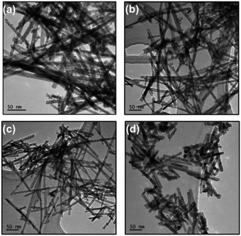 | ||
| Fig. 1 TEM images of (a) CeO2, (b) Ce0.9Mn0.1O2−δ (Mn–CeO2), (c) Ce0.9Co0.1O2−δ (Co–CeO2), and (d) Ce0.9Ni0.1O2−δ (Ni–CeO2) NRs. | ||
Fig. 2a shows the powder X-ray diffraction patterns of CeO2 NRs, Mn–CeO2 NRs, Co–CeO2 NRs, and Ni–CeO2 NRs. The presence of diffraction lines (111), (200), (220), (311), (222), (400), and (331) can be attributed to cubic fluorite structured CeO2 with the space group Fm3m (JCPDS 34-0394).12 Furthermore, the absence of MnOx, CoOx, and NiO phases in the M–CeO2 NRs confirms the formation of Ce0.9M0.1O2−δ (M = Mn, Co, and Ni) solid solution, respectively. The metal (Mn, Co, and Ni) elemental compositions were determined by ICP-OES analysis and the results are described in Table S1.† It can be concluded that the calculated compositions were closed to the nominal composition. Additionally, the diffraction lines of Mn–CeO2, Ni–CeO2, and Co–CeO2 NRs were shifted to higher 2θ angles while compared to pure CeO2 NRs. To verify this observation, the lattice constants (a) were calculated and summarized in Table 1. The lattice constants of Mn–CeO2, Co–CeO2, and Ni–CeO2 NRs were reduced to 5.36, 5.37, and 5.39 Å, respectively, while compared to pure CeO2 NRs (5.41 Å). Thus, the reduction of lattice constant can be attributable to the substitution of the smaller Mn2+ ion (0.58 Å), Co2+ (0.78 Å), and Ni2+ (0.83 Å) ion for the Ce4+ ion (0.97 Å), thereby confirm that the M2+ (M = Mn, Ni, and Co) ions are incorporated into the CeO2 lattice. The solid solution formation of the type Ce0.9M0.1O2−δ (M = Mn, Co, and Ni) was also confirmed by estimation of the lattice parameter obtained via structural refinement of the XRD patterns using Rietveld methodology. The results are depicted in ESI, Fig. S3† and show a very good correspondence between experimental data and simulated curves, confirmed by observing the difference patterns. The obtained lattice parameters of CeO2, Mn–CeO2, Co–CeO2, and Ni–CeO2 were found to be 5.414, 5.357, 5.372, and 5.386 Å, respectively. These values are very close to calculated unit cell parameters (Table 1). Further, the average crystallite sizes were calculated from Scherrer equation using full width at half maximum (FWHM) of the (111) lattice plane and presented in Table 1. The Mn–CeO2, Co–CeO2, and Ni–CeO2 NRs were having lowest crystallite sizes, 7.63, 7.52, and 7.13 nm, respectively, while compared to pure CeO2 NRs (8.41 nm). It confirms that the M2+ dopant reduced crystallite size of CeO2 NRs. The decrease in crystallite sizes for M2+-doped CeO2 NRs can also be confirmed by observing BET surface area results. The BET specific surface area (SBET) of pure CeO2 NRs was 108 m2 g−1. When dopants were incorporated into CeO2 lattice, the SBET of Mn–CeO2, Co–CeO2, and Ni–CeO2 NRs increased, which were 123, 132, 139 m2 g−1, respectively. It can be concluded that the M2+ doping reduced crystallite size and enhanced the specific surface area, which is very important for catalytic reactions. The average pore diameter (dp) and pore volume (vp) values were also calculated from BJH pore size distribution method and shown in Table 1. It was found that the M–CeO2 NRs have smaller pore diameter (23.4–21.5 nm) and larger pore volume (1.05–1.09 cm3 g−1), while compared to pure CeO2 NRs (34.8 nm, 0.86 cm3 g−1).
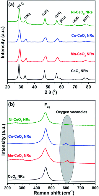 | ||
| Fig. 2 (a) Powder XRD and (b) Raman spectra of pure ceria (CeO2), Ce0.9Mn0.1O2−δ (Mn–CeO2), Ce0.9Co0.1O2−δ (Co–CeO2), and Ce0.9Ni0.1O2−δ (Ni–CeO2) NRs. | ||
| Sample | SA (m2 g−1) | Average pore size (nm) | Pore volume (cm3 g−1) | D (nm) | LP (Å) |
|---|---|---|---|---|---|
| CeO2 | 108 | 34.8 | 0.86 | 8.41 | 5.41 |
| Mn–CeO2 | 123 | 23.4 | 1.05 | 7.63 | 5.36 |
| Co–CeO2 | 132 | 22.8 | 1.07 | 7.52 | 5.37 |
| Ni–CeO2 | 139 | 21.5 | 1.09 | 7.13 | 5.39 |
Fig. 2b shows the Raman spectra of CeO2, Mn–CeO2, Co–CeO2, and Ni–CeO2 NR catalysts. The pure CeO2 NRs were observed to display a prominent band at ∼465 cm−1 corresponding to the Raman active F2g mode of cubic fluorite type CeO2.13 The position of the F2g Raman peak of doped ceria NR catalysts also shifted towards lower wavenumbers when compared to pure CeO2 NRs.14,15 This observation is supported by one additional peak, which was observed at around ∼600–605 cm−1 for Mn–CeO2, Co–CeO2, and Ni–CeO2 NRs. Generally, when dopant is incorporated into ceria lattice, charge imbalance can be occurred. In order to compensate this negative charge, the oxygen vacancies can be delivered in the lattice due to the reduction of Ce4+ to Ce3+.16 These oxygen vacancies concentrations can be determined by measuring the ratio of the defect induced band intensity (ID) and the F2g-band intensity (IF2g). The ID/IF2g values of all catalysts were calculated. The order of oxygen vacancy concentration of catalysts as follows: Co–CeO2 (0.28) > Mn–CeO2 (0.24) > Ni–CeO2 (0.14) > CeO2 (0.08). Among them, cobalt doped ceria NRs possessed high value (0.28) than pure CeO2 (0.08), which reflects that Co–CeO2 NRs had highest amount of oxygen vacancies than pure CeO2 NRs.
Fig. 3a and b shows the Ce 3d and O 1s XPS spectra of CeO2, Mn–CeO2, Co–CeO2, and Ni–CeO2 NRs, respectively. The Ce 3d XP spectra were deconvoluted into total 8 peaks. The same FWHM value maintained for all peaks during peak fitting. The six peaks at 916.72 (u′′′), 907.63 (u′′), 904.09 (u), 898.39 (v′′′), 888.99 (v′′), and 882.37 eV (v) can be attributed to Ce4+, whereas the two peaks at 904.09 (u′) and 884.9 eV (v′) can be attributed to Ce3+.17 After incorporation of dopants into ceria lattice, the binding energies were shifted to lower energy side. It indicates that the Ce–O bond in the doped ceria catalysts become weaker while compared to pure CeO2 NRs. The O 1s XP spectra (Fig. 3b) show three different types of oxygen species for all NR catalysts. The observed binding energies at 529.47–529.2 eV, 531.5–531.2, and 533.3–532.9 eV can be attributed to lattice oxygen (Oα), adsorbed oxygen (Oβ), and water/carbonate species (Oγ), respectively.18 Generally, the presence of surface defects such as Ce3+ ions and oxygen vacancies could play a critical role in the oxidation reactions.12,19 Thus, the relative amount of surface Ce3+ fraction and adsorbed oxygen species were calculated from Ce 3d and O 1s XPS spectra, respectively and summarized in Table 2. It was found that the Co–CeO2 NRs had highest amount of Ce3+ ions (30.4%) and OB species (32.2%) fraction, while compared to Mn–CeO2, Ni–CeO2, and pure CeO2 NRs. This observation was supported by Raman analysis.
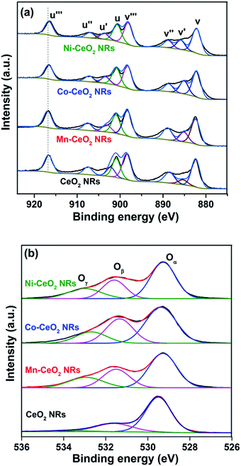 | ||
| Fig. 3 (a) Ce 3d (b) O 1s XPS spectra of pure CeO2 (CeO2), Ce0.9Mn0.1O2−δ (Mn–CeO2), Ce0.9Co0.1O2−δ (Co–CeO2), and Ce0.9Ni0.1O2−δ (Ni–CeO2) NRs. | ||
| Catalyst | [Ce3+] % | [Oβ] % |
|---|---|---|
| CeO2 | 18.3 | 22.4 |
| Mn–CeO2 | 27.2 | 30.1 |
| Co–CeO2 | 30.4 | 32.2 |
| Ni–CeO2 | 24.4 | 29.5 |
The Mn 2p, Co 2p, and Ni 2p XPS spectra of Mn–CeO2, Co–CeO2, and Ni–CeO2 NR catalysts were shown Fig. S4a, S4b, and S4c,† respectively. From Mn 2p XP spectra, the two peaks at 641 and 652 eV could be due to hybridization between Mn 2p3/2 and 2p5/2. Further, Mn 2p3/2 peak can be deconvoluted into three components such as Mn4+ (642.6 eV), Mn3+ (641.1 eV), and Mn2+ (639.2 eV).20 The Co 2p XP spectra show binding energies at around 779.2 eV (Co 2p3/2) and another one around 795.3 eV (Co 2p1/2), which confirms that the Co was in 2+ and 3+ oxidation states.21 In the case of Ni–CeO2 NR catalyst, the binding energies at 855.4 eV (Ni 2p3/2) and 873.5 eV (Ni 2p1/2) indicate the existence of all the Ni species in the 2+ state.22
H2-TPR patterns of CeO2, Mn–CeO2, Co–CeO2, and Ni–CeO2 NR catalysts were shown in Fig. 4. Pure CeO2 NRs show a single broad peak in the range 400–750 °C with a peak maxima at 612 °C, which can be attributed to the reduction of surface and lattice oxygen of ceria.23 Modification with various dopants considerably influences the reducibility of CeO2. Different chemical environments of transition metals interacting with the CeO2 lead to particular reduction temperatures. For the Mn–CeO2 NRs, two peaks were appeared at 313 and 446 °C. The lower temperature reduction peak at 313 °C represent the reduction of MnO2/Mn2O3 to Mn3O4 while the higher temperature reduction at 446 °C can be attributed to the combined reduction of Mn3O4 to MnO and surface Ce4+ to Ce3+ species.12 Similarly, the Co–CeO2 NRs also showed the two reduction peaks at 219 and 461 °C. The peaks at 219 and 461 °C can be assigned to the reduction of Co3O4 to CoO and surface oxygen species of ceria, respectively.23 The reduction profile of Ni–CeO2 NRs shows two peaks around 201 and 370 °C. The primary peak can be attributed to the reactive oxygen species of Ni–CeO2 solid solution.24 Later peak can be attributed to the reduction of strongly interacting NiO species with CeO2 support. Previous reports have shown that the surface reduction of ceria is of particular interest since it gives a major contribution to the CO oxidation activity.1,25–27 From the reduction patterns of doped ceria catalysts, it is noted that the position of surface lattice oxygen peak strongly depends on the nature of dopant and it clearly shifted to lower temperature compared with that of pure CeO2 NRs. Such a difference indicates that transition metals doping introduces higher surface oxygen reactivity and more surface reaction sites. Among the different transition metal doped CeO2 NRs, the Co–CeO2 NRs could weaken the strength of the Ce–O bond through the strong synergetic interaction between CeO2 and CoOx species, and promote desorption of the surface adsorbed oxygen from the CeO2 surface, thereby enhancing the redox property of the catalyst.
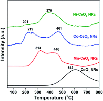 | ||
| Fig. 4 H2-TPR patterns of pure CeO2 (CeO2), Ce0.9Mn0.1O2−δ (Mn–CeO2), Ce0.9Co0.1O2−δ (Co–CeO2), and Ce0.9Ni0.1O2−δ (Ni–CeO2) NRs. | ||
3.2 Catalytic CO oxidation
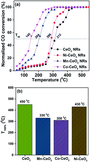
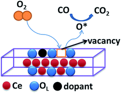
It is well known that CO oxidation is of great importance in both fundamental studies and practical applications.28–33 Hence, CO oxidation reaction was used to assess the catalytic activity of the different transition metal (Mn2+, Ni2+, and Co2+) doped CeO2 NRs. Further, the CO oxidation activity of M–CeO2 NRs were compared with the pure CeO2 NRs. The normalized CO conversions of Mn–CeO2 NRs, Co–CeO2 NRs, Ni–CeO2 NRs, and CeO2 NRs were shown in Fig. 5a. The results indicate that all the transition metal doped ceria catalysts exhibit higher CO oxidation activity compared with that of the undoped CeO2 NRs. Using a 50% extent of CO conversion as a reference, the reaction temperatures (T50) for the CeO2 NRs, Mn–CeO2, Co–CeO2 and Ni–CeO2 catalysts are compared: CeO2 NRs (T50; 312 °C) > Ni–CeO2 NRs (T50; 286 °C) > Mn–CeO2 NRs (T50; 204 °C) > Co–CeO2 NRs (T50; 145 °C). The complete CO conversion (temperature of 100% conversion, T100) of all catalysts was also shown in Fig. 5b. The results showed that there is a large increase of oxidation activity when the CeO2 NRs was doped with transition metals.The importance of vacancy sites on CeO2 towards CO conversion over doped ceria catalysts can be explained by Scheme 1 and the following equations:
 | (1) |
| CO(g) → CO(ads) | (2) |
| CO(ads) + OL → CO(ads)–OL | (3) |
 | (4) |
 | (5) |
From the above equations, OL and  represent the lattice oxygen and oxygen vacancy, respectively. According to eqn (1), the presence of vacancy sites were created due to the transformation of Ce4+ to Ce3+. These oxygen vacancies could be utilized as active sites for adsorbing CO molecules as well as to activate lattice oxygen (eqn (2)–(5)).34 Moreover, these vacancies can be used for enhancing oxygen transportation from bulk to the surface of CeO2 lattice.27 For pure CeO2, the oxygen vacancy is only originated from Ce4+ transforming to Ce3+. However, when dopants incorporated into CeO2 lattice, the quantity of oxygen vacancies can be increased in order to maintain charge neutrality in the lattice. Therefore, the activity of the CO catalytic oxidation for the transition metal doped-CeO2 NRs is enhanced compared to the pure CeO2-NRs.
Among the prepared catalysts, Co–CeO2 NR catalysts showed the highest activity. The light-off temperature (T50) decreases by 167 °C (from 312 °C to 145 °C) after doping a 10% Co. Complete conversion of CO (T100) is achieved at 308 °C for the Co–CeO2 NRs. Similarly, Mn–CeO2 NR catalyst also shown good CO conversion (T50 = 204 °C). On the other hand, Ni–CeO2 NR catalyst showed lower CO oxidation performance (T50 = 286 °C), when compared to the Co–CeO2 and Mn–CeO2 NRs. In order to find out this anomaly, we have carried out XRD for the used Ni–CeO2 NR catalyst and shown in Fig. S5.† Surprisingly, the extra diffraction peak at 44.5° was observed along with CeO2 diffraction lines. The extra peak can be attributed to the metallic Ni.35 These results suggest that the presence of Ni metallic species might be responsible for the drop observed in the CO conversion.
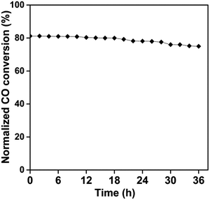
The high performance having Co–CeO2 NRs catalyst also compared with the reported 10% Zr doped CeO2 NRs and their T50 values are described in Table S2.†9 It was found that cobalt doped CeO2 NRs show lowest T50 value while compared to Zr doped CeO2 NRs. It can be concluded that the variable oxidation states and better redox behaviour of cobalt modified CeO2 NRs might be responsible for better CO conversion. To further investigate the resistance of the Co–CeO2 NRs catalyst towards deactivation, long-term stability tests of Co doped CeO2 NRs at 220 °C for 36 h have also been examined and shown in Fig. 6. As shown in Fig. 6, little deactivation (less than 7%) has been found in the stability test. Therefore, we can conclude that the best developed Co–CeO2 NRs catalyst exhibit good stability towards CO oxidation.
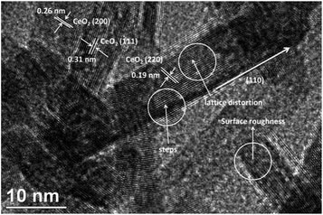
Moreover, the CO conversion of Co–CeO2 and CeO2 NRs were compared with the CeO2 nanoparticles (NP) and shown in ESI, Fig. S6.† It was found that there is a large difference in T50 values between NRs and NPs. Generally, NPs contain [111] lattice plane predominantly on the surface. However, NRs exhibit different crystal planes such as [110] and [100], which are very active than [111] lattice plane. To verify this, we have performed HR-TEM and shown in Fig. 7. It was found that Co–CeO2 NRs (Fig. 7) show the [111], [200], and [220] lattice fringes with the inert planar spacing of 0.311, 0.271, and 0.162 nm, respectively. The appearance of [110] lattice plane along with CeO2 NR also clearly suggests that the growth of NR is occurring along the [110] plane direction. It can be concluded that the highly reactive [110] plane might be exposed to adsorbed CO molecules, which then converted to CO2 by reacting with surface oxygen. In addition, we have compared the HR-TEM images of pure CeO2 and Co–CeO2 NRs (ESI, Fig. S7†). It was found that the majority of the Co doped CeO2 nanorods exhibited relatively rough surfaces with significant surface defects, while compared to pure CeO2 NRs.
Overall, the high surface oxygen content and Ce3+ fraction was also proved by Raman and XPS results. It was found that the Co–CeO2 NR catalysts possessed more oxygen vacancies due to higher content of Ce3+ (Table 2) on the surface, which can tune the catalytic performance by facilitating the activation and transportation of active oxygen species.26,27 H2-TPR results also showed an excellent redox capability of Co–CeO2 NR catalyst. Therefore, the superior catalytic performance of Co–CeO2 NRs could be attributed to the improved structural, surface, and redox properties as well as highly reactive [110] plane.
4. Conclusion
In this study, we prepared different transition metal (M = Mn, Co and Ni) doped CeO2 catalysts with nanorods morphology and CeO2 as a reference by adopting a hydrothermal approach. The incorporation of different dopants in the ceria lattice is reflected by decreased crystallinity through the formation of Ce1−xMxO2−δ NRs which is evidenced by XRD. BET surface area measurements indicate that the NRs have high specific surface areas in the range of 123 to 139 m2 g−1. Average sizes of Ce0.9M0.1O2−δ (M = Mn, Co and Ni) nanocrystallites are in the 7.13–7.63 nm range. Doping with cobalt enhanced the formation of surface oxygen vacancies, which is proved by Raman spectroscopy. Highly reactive [110] planes of CeO2 NRs were also confirmed by HR-TEM. Thus, the modification of ceria with various dopants significantly enhanced the catalytic performance of CO oxidation at lower temperature. Among different types of dopants, cobalt doped CeO2 NRs were found to be the best for low temperature CO oxidation. As per the catalyst characterization studies, the defect sites such as Ce3+ ions, and active surface oxygen species as well as highly reactive [110] planes are found to be favourable for the increased catalytic activity.Acknowledgements
The authors would like to acknowledge RMMF for the providing their comprehensive facilities for the work. Authors also thank P. Selvakannan for his help for HRTEM studies. Authors also thank Prof. Vithal group, Department of Chemistry, Osmania University for their help in Rietveld methodology.References
- P. Venkataswamy, K. N. Rao, D. Jampaiah and B. M. Reddy, Appl. Catal., B, 2015, 162, 122–132 CrossRef CAS
.
- C. Sun, H. Li and L. Chen, Energy Environ. Sci., 2012, 5, 8475–8505 CAS
.
- W. Gao, Z. Zhang, J. Li, Y. Ma and Y. Qu, Nanoscale, 2015, 7, 11686–11691 RSC
.
- P. Sudarsanam, B. Hillary, D. K. Deepa, M. H. Amin, B. Mallesham, B. M. Reddy and S. K. Bhargava, Catal. Sci. Technol., 2015, 5, 3496–3500 CAS
.
- W. Liu, W. Wang, K. Tang, J. Guo, Y. Ren, S. Wang, L. Feng and Y. Yang, Catal. Sci. Technol., 2016, 6, 2427–2434 CAS
.
- Y. Chen, C. Qiu, C. Chen, X. Fan, S. Xu, W. Guo and Z. Wang, Mater. Lett., 2014, 122, 90–93 CrossRef CAS
.
- F. Yang, J. Wei, W. Liu, J. Guo and Y. Yang, J. Mater. Chem. A, 2014, 2, 5662–5667 CAS
.
- K. Zhou, X. Wang, X. Sun, Q. Peng and Y. Li, J. Catal., 2005, 229, 206–212 CrossRef CAS
.
- A. Chen, Y. Zhou, N. Ta, Y. Li and W. Shen, Catal. Sci. Technol., 2015, 5, 4184–4192 CAS
.
- G. Chen, Q. Xu, Y. Yang, C. Li, T. Huang, G. Sun, S. Zhang, D. Ma and X. Li, ACS Appl. Mater. Interfaces, 2015, 7, 23538–23544 CAS
.
- L. Zhou, X. Li, Z. Yao, Z. Chen, M. Hong, R. Zhu, Y. Liang and J. Zhao, Sci. Rep., 2016, 6, 23900 CrossRef CAS PubMed
.
- D. Jampaiah, S. J. Ippolito, Y. M. Sabri, J. Tardio, P. R. Selvakannan, A. Nafady, B. M. Reddy and S. K. Bhargava, Catal. Sci. Technol., 2016, 6, 1792–1803 CAS
.
- S. Hao, J. Hou, P. Aprea and F. Pepe, Appl. Catal., B, 2014, 160–161, 566–573 CrossRef CAS
.
- P. Venkataswamy, D. Jampaiah, K. N. Rao and B. M. Reddy, Appl. Catal., A, 2014, 488, 1–10 CrossRef CAS
.
- W. Y. Hernández, O. H. Laguna, M. A. Centeno and J. A. Odriozola, J. Solid State Chem., 2011, 184, 3014–3020 CrossRef
.
- J. Zhang, J. Guo, W. Liu, S. Wang, A. Xie, X. Liu, J. Wang and Y. Yang, Eur. J. Inorg. Chem., 2015, 2015, 969–976 CrossRef CAS
.
- H. Zhang, F. Gu, Q. Liu, J. Gao, L. Jia, T. Zhu, Y. Chen, Z. Zhong and F. Su, RSC Adv., 2014, 4, 14879–14889 RSC
.
- X. Yao, C. Tang, Z. Ji, Y. Dai, Y. Cao, F. Gao, L. Dong and Y. Chen, Catal. Sci. Technol., 2013, 3, 688–698 CAS
.
- D. Jampaiah, S. J. Ippolito, Y. M. Sabri, B. M. Reddy and S. K. Bhargava, Catal. Sci. Technol., 2015, 5, 2913–2924 CAS
.
- B. Shen, Y. Wang, F. Wang and T. Liu, Chem. Eng. J., 2014, 236, 171–180 CrossRef CAS
.
- Anushree, S. Kumar and C. Sharma, Catal. Sci. Technol., 2016, 6, 2101–2111 CAS
.
- S. Sun, X. Zhao, H. Lu, Z. Zhang, J. Wei and Y. Yang, CrystEngComm, 2013, 15, 1370–1376 RSC
.
- S. A. Mock, S. E. Sharp, T. R. Stoner, M. J. Radetic, E. T. Zell and R. Wang, J. Colloid Interface Sci., 2016, 466, 261–267 CrossRef CAS PubMed
.
- S. Mahammadunnisa, P. M. Kumar Reddy, N. Lingaiah and C. Subrahmanyam, Catal. Sci. Technol., 2013, 3, 730–736 CAS
.
- C. G. Maciel, T. d. F. Silva, M. I. Hirooka, M. N. Belgacem and J. M. Assaf, Fuel, 2012, 97, 245–252 CrossRef CAS
.
- D. Mukherjee, B. G. Rao and B. M. Reddy, Appl. Catal., B, 2016, 197, 105–115 CrossRef CAS
.
- Z. Yang, Z. Fu, Y. Zhang and R. Wu, Catal. Lett., 2010, 141, 78–82 CrossRef
.
- Z. Wu, M. Li and S. H. Overbury, J. Catal., 2012, 285, 61–73 CrossRef CAS
.
- Z. Yang, J. Wei, H. Yang, L. Liu, H. Liang and Y. Yang, Eur. J. Inorg. Chem., 2010, 3354–3359 CrossRef CAS
.
- J. Paier, C. Penschke and J. Sauer, Chem. Rev., 2013, 113, 3949–3985 CrossRef CAS PubMed
.
- J. M. López, A. L. Gilbank, T. García, B. Solsona, S. Agouram and L. Torrente-Murciano, Appl. Catal., B, 2015, 174–175, 403–412 CrossRef
.
- A. Trovarelli, Catalysis by Ceria and Related Materials, Imperial College Press, 2002 Search PubMed
.
- J. Xiao, L. Wan, X. Wang, Q. Kuang, S. Dong, F. Xiao and S. Wang, J. Mater. Chem. A, 2014, 2, 3794–3800 CAS
.
- A. Jha, D.-W. Jeong, Y.-L. Lee, I. W. Nah and H.-S. Roh, RSC Adv., 2015, 5, 103023–103029 RSC
.
- C. A. Chagas, E. F. de Souza, R. L. Manfro, S. M. Landi, M. M. V. M. Souza and M. Schmal, Appl. Catal., B, 2016, 182, 257–265 CrossRef CAS
.
Footnote |
| † Electronic supplementary information (ESI) available: ICP-OES data, T50 values, SEM images and EDX spectra, Rietveld refinement XRD data, Mn 2p, Co 2p, and Ni 2p XPS spectra, CO conversion, and HR-TEM results of the investigated catalysts. See DOI: 10.1039/c6ra13577c |
| This journal is © The Royal Society of Chemistry 2016 |

