RedOx-controlled sorption of iodine anions by hydrotalcite composites

Tatiana G. Levitskaia*a, Sayandev Chatterjeea, Bruce W. Areya, Emily L. Campbella, Yongchun Hongb, Libor Kovarikb, James M. Petersona, Natasha K. Pencea, Jesus Romeroa, Vaithialingam Shutthanandanb, Birgit Schwenzerc and Tamas Vargab
aEnergy and Environment Directorate, Pacific Northwest National Laboratory, Richland, WA 99354, USA. E-mail: Tatiana.Levitskaia@pnnl.gov
bEnvironmental and Molecular Sciences Laboratory, Pacific Northwest National Laboratory, Richland, WA 99354, USA
cPhysical and Computational Sciences Directorate, Pacific Northwest National Laboratory, Richland, WA 99354, USA

Received 20th May 2016 , Accepted 4th July 2016

First published on 18th July 2016


Abstract

The radioactive contaminant iodine-129 (I-129) is one of the top risk drivers at radiological waste disposal and contaminated groundwater sites where nuclear material fabrication or reprocessing has occurred. However, currently there are very few options available to treat I-129 in the groundwater, partially related to the complex biogeochemical behavior of iodine in the subsurface and occurrence of I-129 in the multiple chemical forms. We hypothesize that layered hydrotalcite materials containing redox active transition metal ions offer a potential solution, benefiting from the simultaneous adsorption of iodate (IO3), and iodide (I) anions, which exhibit different electronic and structural properties and therefore may require dissimilar hosts. To test this hypothesis, Cr3+-based materials were selected based on the rationale that Cr3+ readily reduces IO3 in solution. It was combined with either redox-active Co2+ or redox-inactive Ni2+ so that two model materials were prepared by hydrothermal synthesis including Co2+–Cr3+ or Ni2+–Cr3+ (M–Cr). Obtained M–Cr materials composed of Co2+–Cr3+ or Ni2+–Cr3+ layered hydrotalcite and small fractions of Co3O4 spinel or Ni(OH)2 theophrastite phases were structurally characterized before and after uptake of periodate (IO4), IO3, and I anions. It was found that the IO3 uptake is driven by its chemical reduction to I2 and I. Interestingly, in the Co2+–Cr3+ hydrotalcite, Co2+ and not Cr3+ serves as a reductant while in the Ni2+–Cr3+ hydrotalcite Cr3+ is responsible for the reduction of IO3. A different uptake mechanism was identified for the IO4 anion. The Co2+–Cr3+ hydrotalcite phase efficiently uptakes IO4 by a diffusion-limited ion exchange mechanism and is not accompanied by the redox process, while Cr3+ in the Ni2+–Cr3+ hydrotalcite reduces IO4 to IO3, I2 and I. Iodide exhibited high affinity only to the Co–Cr material. The Co–Cr material performed remarkably well for the removal of IO3, I and total iodine from the groundwater collected from the US DOE Hanford site, WA, USA, outperforming non-redox active hydrotalcites (e.g., Mg2+–Al3+) reported previously. This work demonstrates that redox-controlled sorption can be a highly effective method for the treatment of anions based on elements with mobile oxidation states. Further, multiple anions of interest could be simultaneously removed through a combination of approaches.

Introduction

Iodine is a naturally occurring element that is important for human health and is vital for thyroid function. On the other hand, absorption and concentration of radioactive iodine increases risk of thyroid cancer. Significant amounts of radioactive iodine have been released to the environment due to the activities associated with production of nuclear weapons and from accidents at nuclear power plants. Among iodine radioisotopes, by-products of uranium and plutonium fission I-131 and I-129 are particularly hazardous. Iodine-131 with a half-life of about 8 days, is a major public health concern after nuclear accidents (such as at Chernobyl or Fukushima Daiichi nuclear power plants).1 Isotope I-129 has a very long half-life of about 15.7 million years, and its levels build up in the environment over time. Iodine-129 is a risk-contributing contaminant of environmental and health concern at U.S. Department of Energy nuclear waste storage sites such as the Savannah River and Hanford Sites.2 At the Hanford Site located in Washington State, management of I-129 contamination in the 200 Area vadose zone is an essential component for the Hanford Site cleanup program and protection of the Columbia River. One potential management approach is removal of radioiodine from groundwater for safe long-term storage. To date this remains a challenging task.3–5 In subsurface aquatic environments, iodine exhibits complex biogeochemical behavior and occurs in multiple inorganic and organic chemical forms and oxidation states varying from −1 to +7.6,7 In the Hanford groundwater, iodine exists predominantly as iodate (IO3), which accounts for up to about 70% of total iodine with iodide (I) and organoiodine being minor components.4 This implies that to be effective, separation methods should satisfy two requirements including high affinity for the dissimilar forms of iodine and sufficient selectivity for different iodine species to ensure their removal from the complex solutions containing excess of common environmental anions (carbonate, chloride, sulphate, other) found in groundwater.

For several decades considerable research effort has been directed toward identifying synthetic materials for removing or attenuating transport of iodine in the groundwater.8–10 Clay-like hydrotalcite materials commonly known as layered double hydroxides (LDHs) are attractive candidates as they have been extensively studied for the removal of harmful anions from contaminated water.11 The LDH materials can be represented by the general formulae [M1−x2+Mx3+(OH)2]x+(An)x/nyH2O, where M2+ is a divalent and M3+ is a trivalent cation; the value of x is equal to the molar ratio of M3+/(M2+ + M3+), whereas An is the interlayer anion. These materials usually uptake anions through ion exchange. Variation of the identities of M2+, Mm+, and An give rise to a large class of isostructural materials with physicochemical properties that can be tailored to achieve high selectivity and capacity for the uptake of an anion of interest12 and also be regenerated for reuse.13 Application of hydrotalcites for the selective sorption of various anions of iodine has been recently reviewed.8,9 Among tested hydrotalcites, Mg2+–Al3+ materials showed promise for iodine removal and have been preferentially investigated. For instance, iodide has been immobilized using Mg2+–Al3+ LDH by exchanging the parent Cl anion with I.14 In another study, calcined Mg2+–Al3+–CO32− material was used to remove iodide from contaminated ground water.15 Hydrotalcite-type compounds consisting of brucite-like positively charged layers with the similar Mg2+–Al3+–CO32−–NO3 chemical composition showed promise for IO3 uptake.16,17 The main drawback of the Mg2+–Al3+ LDH materials is insufficient selectivity toward iodide and iodate anions. Several studies demonstrate that iodine removal efficiency of uncalcined Mg2+–Al3+ materials is limited by their high affinity toward carbonate12,13 present in groundwater, raising concerns regarding their applicability for environmental separations.8,9 Presence of other anions also affects iodine removal. Kang et al. reported that Mg2+–Al3+ hydrotalcite exhibits high efficiency of iodide uptake in competing anion free solutions.18 However, when this and other hydrotalcites were tested in dilute sodium salt (nitrate, nitrite, aluminate, hydroxide) solutions the iodide uptake was significantly reduced.19,20 A similar effect was observed for iodide adsorption using Zn-bearing hydrotalcites in sodium chloride solutions.21

One potential approach to increase LDH selectivity toward iodine adsorption is to introduce soft polarizable metal ions into the LDH structure which have tendency to strongly bind soft bases such as iodine anions.22 Indeed, Hg and Ag-bearing sulfide minerals demonstrate high affinity for iodine anions as reported in the review by Mattigold et al. (and references therein),10 however toxicity limits their utilization for groundwater treatment. We hypothesize that the presence of the borderline soft redox-active metal ions in the LDH structure will have a weaker but similar effect and may improve their selectivity toward adsorption of the iodine anions. Another objective of this work is to examine if the application of LDH material containing redox-active transition metals is beneficial for selective uptake of the iodine anions due to their potential conversion to the oxidation state and chemical form most complimentary with the electronic and structural environment of the LDH material. Introduction of a secondary redox uptake mechanism in addition to anion exchange can be particularly useful in designing hydrotalcite materials for the simultaneous adsorption of iodate and iodide anions, which exhibit different electronic and structural properties and therefore may require dissimilar hosts. In fact, this can pave the way for a multi-modal approach to removal of multiple anions, where some of the anions can be removed by a simple ion-exchange mechanism, while the others can be removed through more complicated chemical or redox pathways. As proof-of-concept, we are examining borderline soft, redox-active transition metals such as Co2+ and Cr3+ for the selective uptake of anions of iodine, and their subsequent redox change. Indeed, our previous exploratory work has indicated that among the large array of LDH compounds synthesized and tested for their affinity toward iodate and iodide, Cr3+-containing hydrotalcite materials exhibited effective IO3 uptake from the Hanford groundwater at high sorption capacity.23 These scoping results prompted us to elucidate and compare uptake mechanisms for iodine anions using two materials based on Co2+–Cr3+ and Ni2+–Cr3+ (referred in the text as Co–Cr and Ni–Cr or jointly as M–Cr) as model redox-active compounds containing a combination of the borderline soft Co2+ and Ni2+ divalent transition metal ions. In addition, Co2+ can be easily oxidized to Co3+ while Ni2+ is expected to retain a +2 oxidation state; this difference allows elucidation of the role of the model redox mobile Cr3+ in the uptake of the iodine anions. It is understood that Cr-based materials are unlikely candidates for the practical applications due to the toxic properties of Cr(VI). Rather it serves as a convenient redox-active model allowing benchmarking of redox-driven ion exchange mechanisms and design of environmentally friendly advanced hydrotalcite materials to manage challenging redox mobile subsurface contaminants that include not only iodine, but As, Hg, Tc, and others as well. In this work, the mechanism and sorption behavior of M–Cr toward three different anionic species of iodine including IO4, IO3 and I was explored. Even though periodate is anticipated to be the only minor iodine species in the subsurface, its investigation is essential to understand redox behaviour of iodine upon incorporation in the hydrotalcite structure.

Experimental

Materials

All chemicals (reagent grade) were purchased from Sigma Aldrich or Baker & Adamson Chemicals and used without further purification. Distilled deionized (DI) water was used for the preparation of the aqueous solutions. Iodine uptake from the groundwater was measured using 25 mM solutions of IO4, IO3 or I prepared using the well 299-W19-36 water collected from the US DOE Hanford site, WA, USA. The major constituents of the groundwater are listed in Table S1.

Material synthesis

While coprecipitation methods have been widely used for the synthesis of LDH composites of the form M–Cr, this work employed hydrothermal methods, which we find result in higher crystallinity. The modified synthetic procedure for the M–Cr (M = Co or Ni) hydrotalcites was adapted from hydrothermal syntheses reported elsewhere.24 In a general procedure, the divalent transition metal and Cr3+ nitrate or chloride salts were dissolved in ∼50 mL deionized water at a 4[thin space (1/6-em)]:[thin space (1/6-em)]1 molar ratio. The solution was stirred for about an hour followed by the addition of 0.5 M NaOH solution under stirring until a pH of 12 was achieved. The mixture was transferred to a Teflon-lined autoclave and kept at 110 ± 5 °C for 72 hours to yield the aggregate. The obtained solid was gravity-filtered, washed with excess water, and dried. To determine the metal composition of the obtained products, massed amounts of the materials were dissolved in concentrated HNO3, diluted with water as appropriate and analyzed by Inductively Coupled Plasma-Optical Electron Spectroscopy. The elemental inorganic carbon analysis was conducted by Atlantic Microlab, Inc. (Norcross, GA).

Kinetics of iodine uptake

Uptake of IO4 or IO3 anions from DI water and Hanford groundwater collected from the well 299-W19-36 was monitored and quantified by Raman spectroscopy. Raman measurements were performed with an InPhotonics RS2000 high-resolution Raman spectrometer equipped with a thermoelectrically cooled charged coupled device (CCD) detector operating at −55 °C; a 670 nm 150 mW diode laser as the excitation source; and focused fiber optic probe RamanProbe™ operated in a 180° back reflection mode. An integration time of 10 s was used for each acquisition, and 10–20 acquisitions were taken and averaged for each sample. Typical sample preparation involved rigorous mixing 100 mg of M–Cr material with 1 mL of 0.025 M KIO3 or KIO4 solution in DI or groundwater in a glass vial. The vial was then centrifuged at 4000 rpm for about 10 minutes until the sorbent settled at the bottom. The liquid phase was continuously monitored for 3 hours. After 3 hours, the solid LDH material was re-suspended in the solution and allowed to stir overnight. Raman measurements were resumed at 24 hours post initial contact. The spectra were baseline-corrected and normalized to the water band. The Raman intensity of the IO3 band at 803 cm−1 (ref. 25) or IO4 band at 793 cm−1.26 in the initial 0.025 M aqueous solutions were compared to the intensities of the corresponding bands at each time point and used to quantify the iodine uptake by the materials.

Characterization techniques

Understanding the structural and morphological features of the LDH materials before and after iodine exposure was achieved by X-ray diffraction (XRD), scanning electron microscopy (SEM)/electron dispersive spectrometry (EDS), and transmission electron microscopy (TEM) studies. Changes of the metal center chemical environment upon iodine uptake as well as iodine speciation in the LDH matrix was done through X-ray photoelectron spectroscopy (XPS) and in situ TEM studies. To prepare iodine-loaded LDH samples, ∼100 mg of the LDH material was contacted with 5 mL of the 0.5 M I, IO3, or IO4 DI water solution under agitation at room temperature. In 24 hours the liquid phase was removed from the sample after centrifugation, and the loaded composite was rinsed with DI water and air-dried.

XRD patterns of the samples were recorded on a Philips X'pert Multi-Purpose Diffractometer (MPD) (PANAlytical, Almelo, The Netherlands) equipped with a fixed Cu anode operating at 45 kV and 40 mA. XRD patterns were collected in the 5–100° 2θ-range with 0.04° steps at a rate of 5 s per step. Phase identification was performed using JADE 9.5.1 from Materials Data Inc., and the 2012 PDF4+ database from ICSD. The lattice parameters and volume-averaged crystallite sizes were calculated from whole-pattern fitting TOPAS v5 (Bruker AXS GmbH, Germany).

XPS data were recorded on a Phi5000 Versa Probe system equipped with a monochromatic Al Kα X-ray source (1486.7 eV) and a hemispherical analyzer. Powder samples were mounted using double-sided carbon conductive tape attached to a stainless steel sample holder. The instrument was calibrated for Cu (2p3/2) at 932.6 (±0.1 eV) with the FWHM (full with at half maximum) of 0.98 eV. The surface charge was eliminated by charge neutralizer and correction of data referencing the 284.5 eV C 1s peak. The percentages of individual elements detected were determined from the relative composition analysis of the peak areas of the bands on the basis of the relative peak areas and their corresponding sensitivity factors to provide relative compositions. XPS peak fitting was done using the software XPSPEAK41 with Shirley type background and 20% GL (Gaussian–Lorentzian ratio). The satellite peaks were fitted with parameters given in literature.27,28

SEM analysis was performed using the FEI Quanta 3DFEG Dual Beam microscope operated at 10–20 kV. The samples were prepared by two independent methods; in the first method, the sample particles were dispersed onto carbon tape and coated with ∼5 nm of carbon to minimize charge effects. In the second method, samples were mounted on the tape and polished using typical metallographic techniques to avoid colloidal silica for polishing. Compositional analysis was performed with Oxford 80 mm2 SDD electron dispersive spectrometry (EDS) detector. For quantitative EDS analysis, calculated K factors provided by INCA software were used. No correction for absorption within the specimen was performed. Both secondary electron images (SE) and backscatter electron images (BSE) were recorded.

TEM analysis was performed using the FEI Titan 80-300 operated at 300 kV. The information limit of the microscope was below 0.1 nm. Imaging of the focused ion beam (FIB)-prepared samples was done under low electron dose conditions to minimize beam-induced damage. All images were digitally recorded using a CCD camera and analyzed using Gatan digital micrograph. Compositional analysis was performed with EDAX Si(Li) EDS detector.

Batch contact testing

The M–Cr materials were tested in the systematic batch contact experiments using Hanford groundwater collected from the well 299-W19-36. The total iodine content in the groundwater was determined by ICP-MS to be 8.6 ± 0.9 μg L−1. In the batch contact tests to determine M–Cr sorption efficiency for total iodine, unmodified groundwater was used. To determine sorption efficiency of M–Cr for the individual iodine anions, concentration of IO3 or I in the groundwater was adjusted with either KIO3 or NaI to 15 to 130[thin space (1/6-em)]000 μg L−1. Periodate is not expected to be present in the Hanford groundwater,4 and was not tested in the batch contact studies. For each batch contact sample, 70 ± 5 mg of material was contacted with 15 mL of the test groundwater solution. The samples were placed in the 20 mL glass scintillation vials, agitated for 24 hours at room temperature, and centrifuged. The contact time was selected based on the sorption kinetics measurements demonstrating that sorption is complete in 24 h. The initial pre-contact and post-contact solutions were subjected to the ICP-MS analysis to determine iodine concentration. To quantify the efficiency of iodine removal, the distribution coefficient, Kd (mL g−1), was calculated by using eqn (1),
 
image file: c6ra13092e-t1.tif(1)
where Ci is the initial concentration of iodine in the groundwater, Cg is the equilibrium concentration of iodine in the post-contact groundwater, VGW is the volume of iodine solution in groundwater in milliliters, and WC is the weight of the dry M–Cr material in grams.

Iodine analysis was done using ICP-MS. The instrument was calibrated using high-purity National Institute of Standards and Technology (NIST)-traceable calibration standards to generate calibration curves and verify continuing calibration during the analytical run. All standard preparations and sample dilutions were done using a 0.5% Spectrasol solution CFA-C to prevent build-up/memory of iodine in the ICP-MS introduction system.

Results and discussion

M–Cr synthesis and characterization

In the material synthesis, the 4-fold molar excess of the divalent transition metal relative to the trivalent Cr3+ was used based on the previous observations that LDH materials with high M2+[thin space (1/6-em)]:[thin space (1/6-em)]M3+ stoichiometric ratio facilitated IO3 (ref. 16 and 29) and I (ref. 28 and 29) uptake. For the [M1−x2+Mx3+(OH)2]x+(An)x/nyH2O hydrotalcite, the over layer charge is determined by the M2+[thin space (1/6-em)]:[thin space (1/6-em)]M3+ ratio,30 and materials with low charge density resulting from low content of M3+ ions favor soft charge-diffuse iodine anions. Based on the ICP-OES analysis, the M[thin space (1/6-em)]:[thin space (1/6-em)]Cr molar ratio in the obtained materials was determined to be 2.8 ± 0.1 for Co–Cr and 4.4 ± 0.1 for Ni–Cr composites, respectively. Elemental inorganic carbon analysis suggests presence of the carbonate in both materials, so that the CO32−[thin space (1/6-em)]:[thin space (1/6-em)]Cr molar ratio is 0.36 ± 0.02 and 0.174 ± 0.005 for Co–Cr and Ni–Cr products, respectively; atmospheric CO2 dissolved in the alkaline synthetic mixtures being the source of carbonate.

IR spectra of the obtained solid materials exhibited a moderately strong band at ∼1350 cm−1 as well as bands in the 820–850 cm−1 region which are assigned to the asymmetric stretching and the out-of-plane deformation of free interlamellar carbonate anions with D3h symmetry in the composites.31 Additional bands observed at 1480–1490, 1388 (shoulder), and 1067 cm−1 are also attributed to intercalated carbonate ions, but in the lower C2v symmetry,32,33 suggesting binding of these carbonates by the hydrotalcites. A broad band centered at ca. 3440 cm−1 is due to the νO–H stretching vibration of hydrogen-bonded geminal OH groups and water molecules, and that at 1636 cm−1 corresponds to the bending of water.34 Other IR bands appeared at the 500–700 cm−1 spectral region, and were assigned to the vibrations of the metal–oxygen bonds.35 Interestingly no presence of nitrate anion in the prepared materials was observed by IR spectroscopy suggesting preferential incorporation of the carbonate anion available due to the aerated conditions of the synthesis.

XRD studies of the materials were conducted to identify the structure of the composites. The XRD patterns of the Co–Cr and Ni–Cr materials (Fig. 1A and B) are characterized by the presence of two distinct phases, one phase being significantly more crystalline than the other, so that M–Cr have composite structures. The diffractograms of the highly crystalline phases in the Co–Cr and Ni–Cr materials are consistent with the respective structures of the cubic spinel Co3O4 (JCPDS no. 09-0418)36 and theophrastite, the anhydrous form of Ni(OH)2 (JCPDS no. 59-0463).36 Based on the relative intensities, it should be noted that while a significant fraction of the cubic spinel Co3O4 is present in the Co–Cr composite, the Ni(OH)2 phase constitutes only a tiny portion of the Ni–Cr composite. The second phase in both composite materials exhibits a nearly identical broad and highly polycrystalline diffraction pattern that is strikingly similar to the previously reported hydrotalcite composite of the formula Mg6Al2CO3(OH)16·4H2O (JCPDS no. 14-0191)36 characterized by a layered structure with intercalated CO32− anions. The diffraction pattern of this polycrystalline phase also matches that of previously observed hydrotalcite-like Co–Cr and Ni–Cr carbonates obtained by the coprecipitation method.32,33,37 The XRD profiles of the polycrystalline phases obtained in this work are sharper and more intense than ones obtained by the simple co-precipitation method as illustrated in above reports by del Arco et al. and Kooli et al.,32,33,37 which is attributed to the improved crystallinity of the hydrotalcite products resulting from the prolonged hydrothermal syntheses. In unison with literature, the XRD results indicate that the hydrotalcite phases of the prepared M–Cr composites possess highly layered structural framework.


image file: c6ra13092e-f1.tif
Fig. 1 XRD patterns of the M–Cr materials before and after exposure to the aqueous solution of 10−1 M of I, IO3, or IO4. (A) Co–Cr, (B) Ni–Cr.

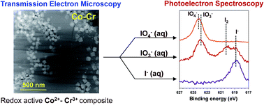
XPS measurements were conducted to identify the oxidation states associated with the key components of the prepared composites. Due to the high redox mobility of Co and Cr transition metals (at pH = 14, standard electrode potentials of the Co3+/Co2+ and CrO42−/Cr(OH)3 couples are 0.17 V and −0.13 V, respectively38), oxidation of the starting Co2+ and Cr3+ ions can be expected during the hydrothermal synthesis. The obtained XPS spectra for the M–Cr composites are shown in Fig. 2 (black traces), observed atomic compositions and the binding energy assignments are given in Tables 1 and S2, respectively. For the Co–Cr composite, the Co 2p3/2 spectrum shows a broad peak, which envelops the 780.9 and 779.8 eV regions corresponding to Co2+ (87%) and Co3+ (13%), respectively (Fig. 2 and Table 2).39,40 Likewise, Cr 2p1/2/2p3/2 spectral region shows bands with the maxima at 586.8 and 577.2 eV suggesting presence of Cr3+ (77%)41 as well as shoulders at 588.7 and 579.2 eV suggesting presence of Cr6+ (23%)42 (Fig. 2 and Table 2). The O 1s spectrum (Fig. S1A, black trace; Table S2) shows a broad peak enveloping bands at 531.4 eV assigned to a mixed +2/+3 cobalt oxide43 and 530.7/530.6 eV assigned to Cr2O3 (ref. 44) and CrO3.42 The low intensity Cl 2p3/2 spectrum at 198.7 eV (ref. 45) is assigned to the presence of chloride in the hydrotalcite phase. For the Ni–Cr material, the Ni 2p3/2 spectrum is attributed to Ni(OH)2 (Fig. 2 and Table 2).28 The Cr spectral region is nearly identical to that of observed for the Co–Cr material and indicates that Cr3+ and Cr6+ contribute respective 78 and 22% to the overall intensity (Fig. 2 and Table 2).41,42 The O 1s spectrum (Fig. S1B, black trace; Table S2) shows a broad peak as well, centered around 530.7/530.6 eV assigned to Cr2O3 (ref. 44) and CrO3 (ref. 42) with a shoulder at 532.0 eV corresponding to Ni(OH)2.46


image file: c6ra13092e-f2.tif
Fig. 2 XPS spectral overlays for the M–Cr materials before (black traces) and after 24 hour exposure to 10−1 M I (violet traces), IO3 (red traces) or IO4 (orange traces). (A) Co 2p3/2 region for Co–Cr, (B) Cr 2p1/2 and 2p3/2 regions for Co–Cr, (C) I 3d5/2 region for Co–Cr, (D) Co 2p3/2 region for Ni–Cr, (E) Cr 2p1/2 and 2p3/2 regions for Ni–Cr, (F) I 3d5/2 region for Ni–Cr. The respective composition percentages obtained from deconvoluting the spectra are presented in Table 2.
Table 1 Obtained by XPS atomic composition of the M–Cr samples before and after 24 hour exposure to the aqueous solution of 10−1 M of I, IO3, or IO4
Composite C 1s O 1s Cl 2p Co 2p Cr 2p I 3d
Co–Cr 24.3 50.7 3.2 17.2 4.5 NA
Co–Cr/I 23.4 52.4 1.4 17.4 4.8 0.6
Co–Cr/IO3 27.0 50.6 1.5 15.5 4.2 1.3
Co–Cr/IO4 26.0 51.4 1.7 14.8 3.1 3.1

Composite C 1s O 1s Ni 2p Cr 2p I 3d
Ni–Cr 27.1 52.8 16.6 3.4 NA
Ni–Cr/I 21.7 55.6 18.9 3.2 0.0
Ni–Cr/IO3 23.0 54.3 17.0 3.9 1.7
Ni–Cr/IO4 23.5 53.9 16.8 3.6 2.3


Table 2 Atomic percentages obtained from XPS (standard division = 5%) of oxidation states of Co, Ni, Cr and I in the M–Cr samples before and after 24 hour exposure to the aqueous solution of 10−1 M of I, IO3, or IO4
Sample Co% Cr% I%
Co2+ Co3+ Cr3+ Cr6+ IO4 IO3 I2 I
Co–Cr 87 13 77 23 NA
Co–Cr–I 91 9 76 24 100
Co–Cr–IO3 78 22 75 25 46 26 28
Co–Cr–IO4 87 13 80 20 100

Sample Ni% Cr% I%
Ni2+ Cr3+ Cr6+ IO4 IO3 I2 I
Ni–Cr 100 78 22 NA
Ni–Cr–I 100 70 30
Ni–Cr–IO3 100 69 31 44 24 32
Ni–Cr–IO4 100 60 40 48 27 13 12


SEM images of the Co–Cr composite (Fig. 3A) shows powdery particles that aggregate together to form a cake-like heterogeneous matrix. The powdery morphology of the composite indicates a large surface area facilitating the uptake of anions. Upon further magnification, microcrystalline granules embedded onto the heterogeneous matrix are observed. EDS measurements indicate that the composition of the hydrotalcite-like heterogeneous matrix is distinctly different from the granules largely comprised of the Co3O4 spinels (Table 3). The granules are enriched in Co so that Co[thin space (1/6-em)]:[thin space (1/6-em)]Cr ratio is about 6.4[thin space (1/6-em)]:[thin space (1/6-em)]1 compared to the heterogeneous phase with Co[thin space (1/6-em)]:[thin space (1/6-em)]Cr ratio of about 2.4[thin space (1/6-em)]:[thin space (1/6-em)]1. The hydrotalcite phase showed the presence of Cl, suggesting intercalated chloride anion (Table S3). These results are further supported by the TEM structural data (Fig. 4), which reveal a two-phase system comprising of particles with cuboidal microcrystalline structure embedded in the heterogeneous matrix. The heterogeneous matrix with significant presence of both Cr and Co, shows a highly diffused diffraction (Fig. 4F) further supporting the polycrystalline structure, characterized by small (>5 nm), highly distorted polycrystalline sheets observed by HAADF imaging (Fig. 4E). The HAADF and diffraction patterns of the Co-enriched cuboids confirm a highly ordered Co3O4 spinel structure with Co2+ and Co3+ being located at the tetrahedral and octahedral sites respectively (Fig. 4C and D).47 Small amounts of Cr and Cl associated with the Co3O4 spinel phase is presumably due to their bleeding from the adjacent heterogeneous matrix. The cuboidal particles are observed to agglomerate and form porous regions (Fig. 4B).


image file: c6ra13092e-f3.tif
Fig. 3 Representative SEM images of the M–Cr composites: untreated Co–Cr (A) and Ni–Cr (E) or exposed for 24 hour to the aqueous solutions of 10−1 M IO4 (Co–Cr: B and Ni–Cr: F); 10−1 M IO3 (Co–Cr: C and Ni–Cr: G); and 10−1 M I (Co–Cr: D and Ni–Cr: H).
Table 3 Summary of EDS and elemental mapping of the M–Cr samples before and after exposure to the aqueous solution of 10−1 M of I, IO3, or IO4
M–Cr Analyte Dominant phase M[thin space (1/6-em)]:[thin space (1/6-em)]Cr[thin space (1/6-em)]:[thin space (1/6-em)]I ratio Details of elemental mapping
a The region measured was cracked on the surface.
Co–Cr Hydrotalcite 2.4[thin space (1/6-em)]:[thin space (1/6-em)]1[thin space (1/6-em)]:[thin space (1/6-em)]NA Regions 1 and 2 in Fig. S2, Table S3
Spinel 6.4[thin space (1/6-em)]:[thin space (1/6-em)]1[thin space (1/6-em)]:[thin space (1/6-em)]NA Regions 3, 4 and 5 in Fig. S2, Table S3
Ni–Cr Hydrotalcite 2.6[thin space (1/6-em)]:[thin space (1/6-em)]1[thin space (1/6-em)]:[thin space (1/6-em)]NA Regions 6 and 7 in Fig. S2, Table S3
Theophrasite 6.3[thin space (1/6-em)]:[thin space (1/6-em)]1[thin space (1/6-em)]:[thin space (1/6-em)]NA Region 8 in Fig. S2, Table S3
Co–Cr IO4 (24 hours) Hydrotalcite 2.5[thin space (1/6-em)]:[thin space (1/6-em)]1[thin space (1/6-em)]:[thin space (1/6-em)]0 Region 1 in Fig. S4, Table S4
Spinel 6.1[thin space (1/6-em)]:[thin space (1/6-em)]1[thin space (1/6-em)]:[thin space (1/6-em)]0 Region 2 in Fig. S4, Table S4
Not identifieda 1.9[thin space (1/6-em)]:[thin space (1/6-em)]1[thin space (1/6-em)]:[thin space (1/6-em)]0.4 Region 3 in Fig. S4, Table S4
IO4 (7 days) Hydrotalcite 1.7[thin space (1/6-em)]:[thin space (1/6-em)]1[thin space (1/6-em)]:[thin space (1/6-em)]0.4 Regions 5 and 6 in Fig. S4, Table S4
Spinel 6.9[thin space (1/6-em)]:[thin space (1/6-em)]1[thin space (1/6-em)]:[thin space (1/6-em)]0.4 Region 4 in Fig. S4, Table S4
IO3 (24 hours) Hydrotalcite 2.7[thin space (1/6-em)]:[thin space (1/6-em)]1[thin space (1/6-em)]:[thin space (1/6-em)]0.5 Regions 1 and 2 in Fig. S6, Table S5
Spinel 6.6[thin space (1/6-em)]:[thin space (1/6-em)]1[thin space (1/6-em)]:[thin space (1/6-em)]0.1 Region 3 in Fig. S6, Table S5
IO3 (7 days) Hydrotalcite 1.7[thin space (1/6-em)]:[thin space (1/6-em)]1[thin space (1/6-em)]:[thin space (1/6-em)]0.4 Regions 5 and 6 in Fig. S6, Table S5
Spinel 6.7[thin space (1/6-em)]:[thin space (1/6-em)]1[thin space (1/6-em)]:[thin space (1/6-em)]0.3 Region 4 in Fig. S6, Table S5
I (24 hours) Hydrotalcite 2.6[thin space (1/6-em)]:[thin space (1/6-em)]1[thin space (1/6-em)]:[thin space (1/6-em)]0.1 Regions 1 and 2 in Fig. S8, Table S6
Spinel 6.4[thin space (1/6-em)]:[thin space (1/6-em)]1[thin space (1/6-em)]:[thin space (1/6-em)]0.1 Regions 3 and 4 in Fig. S8, Table S6
I (7 days) Hydrotalcite 2.5[thin space (1/6-em)]:[thin space (1/6-em)]1[thin space (1/6-em)]:[thin space (1/6-em)]0.6 Regions 5 and 6 in Fig. S8, Table S6
Ni–Cr IO4 (24 hours) Hydrotalcite 2.6[thin space (1/6-em)]:[thin space (1/6-em)]1[thin space (1/6-em)]:[thin space (1/6-em)]0.2 Regions 1 and 3 in Fig. S10, Table S7
Theophrasite 6.7[thin space (1/6-em)]:[thin space (1/6-em)]1[thin space (1/6-em)]:[thin space (1/6-em)]0.5 Region 2 in Fig. S10, Table S7
IO4 (7 days) Hydrotalcite 5.5[thin space (1/6-em)]:[thin space (1/6-em)]1[thin space (1/6-em)]:[thin space (1/6-em)]2.3 Regions 4 and 5 in Fig. S10, Table S7
IO3 (24 hours) Hydrotalcite 2.6[thin space (1/6-em)]:[thin space (1/6-em)]1[thin space (1/6-em)]:[thin space (1/6-em)]0.4 Regions 1 and 2 in Fig. S11, Table S8
Theophrasite 7.0[thin space (1/6-em)]:[thin space (1/6-em)]1[thin space (1/6-em)]:[thin space (1/6-em)]0.1 Region 3 in Fig. S11, Table S8
IO3 (7 days) Hydrotalcite 5.1[thin space (1/6-em)]:[thin space (1/6-em)]1[thin space (1/6-em)]:[thin space (1/6-em)]1.8 Regions 4–6 in Fig. S11, Table S8
I (24 hours) Hydrotalcite 2.8[thin space (1/6-em)]:[thin space (1/6-em)]1[thin space (1/6-em)]:[thin space (1/6-em)]0 Region 2 in Fig. S12, Table S9
Theophrasite 6.4[thin space (1/6-em)]:[thin space (1/6-em)]1[thin space (1/6-em)]:[thin space (1/6-em)]0 Regions 1 and 3 in Fig. S12, Table S9
I (7 days) Hydrotalcite 4.4[thin space (1/6-em)]:[thin space (1/6-em)]1[thin space (1/6-em)]:[thin space (1/6-em)]0 Regions 4 and 5 in Fig. S12, Table S9


image file: c6ra13092e-f4.tif
Fig. 4 (A) Representative TEM image of the Co–Cr composite showing cuboidal microcrystalline structures embedded in a heterogeneous matrix. (B) Higher magnification TEM image showing cuboidal particles to agglomerate and form porous regions. (C) HAADF of cuboids consistent with spinel Co3O4 structure. (D) Diffraction map of cuboids consistent with spinel Co3O4 structure. (E) HAADF image of heterogeneous embedding matrix showing small (<5 nm), highly distorted and poorly crystalline sheets. (F) Diffraction map of heterogeneous matrix showing highly diffused rings.

SEM image of the Ni–Cr composite (Fig. 3E) shows a cake-like morphology similar to the Co–Cr composite, displaying microcrystalline granular particles being embedded onto a hydrotalcite like heterogeneous matrix. The Ni[thin space (1/6-em)]:[thin space (1/6-em)]Cr ratio in the heterogeneous matrix and in the granules is about 2.6[thin space (1/6-em)]:[thin space (1/6-em)]1 and 6.3[thin space (1/6-em)]:[thin space (1/6-em)]1, respectively (Table 3). The microscopy results are consistent with the X-ray diffractograms for both M–Cr composites and demonstrate the presence of two distinct phases in each material, the highly crystalline phase being consistent with a cubic spinel Co3O4 for Co–Cr material or with Ni(OH)2 theophrastite phase for Ni–Cr, while the less crystalline heterogeneous phase is consistent with a hydrotalcite like structure.

Overall, based on the elemental analysis XPS, and microscopy results, as well as structural similarity of the heterogeneous M2+–Cr3+ phases of the materials obtained in this work with the corresponding literature hydrotalcite carbonates,30 it is concluded that hydrotalcite phases mainly have general composition of [M1−xCrx(OH)2]Ax/2·nH2O, where A is intercalated anion; predominantly carbonate for Ni2+–Cr3+ and carbonate/chloride mixture for Co2+–Cr3+. These polycrystalline phases incorporate nearly entire stoichiometric amount of Cr used in the synthesis of M–Cr materials, with a negligible amounts getting incorporated in the second crystalline phases (as evidenced by the XPS and TEM results above).

Kinetics of iodine uptake

The affinity of the synthesized materials toward iodine and kinetics of its uptake was evaluated using IO4 and IO3 anions. In these experiments, uptake of IO4 and IO3 anions from the DI water or Hanford groundwater was monitored by Raman spectroscopy. In these experiments, about 100 mg of the composite was contacted with 1 mL of 25 mM solution of IO4 or IO3. The anion uptake with time was quantified by the reduction of the intensity of the corresponding Raman band at 793 (ref. 26) or 803 cm−1 (ref. 25) in the aqueous contact phase. Both materials exhibited highly efficient and fast uptake of IO4 and IO3 anions so that about 90% of iodine was removed during the first 3 hours of contact and sorption was complete in or before 24 hours. Nearly identical sorption results were obtained for both anions regardless of the solution matrix (DI water or Hanford groundwater). Fig. 5 shows representative plots for IO3 uptake from the Hanford groundwater by Co–Cr and Ni–Cr materials. The insets of Fig. 5 show that concentration of IO3 remaining in solution can be fit to a logarithmic behaviour with respect to time, suggesting a first order of IO3 removal kinetics. The first order kinetic rate constants, obtained from the respective slopes, are −7.02 × 10⁻⁴ s−1 for the Co–Cr composite and −8.06 × 10⁻⁴ s−1 for the Ni–Cr composite respectively.
image file: c6ra13092e-f5.tif
Fig. 5 Kinetics of IO3 removal by 100 mg composite from 1 mL of 0.025 M IO3 solution in Hanford ground water monitored by the progressive reduction of the Raman intensity of 803 cm−1 IO3 band with time; the insets show a plot of logarithm of IO3 molar concentration in the contact solutions vs. time. (A) Co–Cr, regression analysis for the inset plot: ln[IO3] = −7.02 × 10⁻⁴t − 3.73, R2 = 0.99 (B) Ni–Cr, regression analysis for the inset plot: ln[IO3] = −8.06 × 10⁻⁴t − 3.70, R2 = 0.99.

Characterization of iodine-loaded composites

X-ray diffraction. The XRD patterns of the Co–Cr composite exposed for 24 hours to the 0.1 M aqueous solutions of individual iodine anions are nearly identical to the diffraction pattern of unexposed Co–Cr (Fig. 1A), with the only noticeable change being reduced crystallinity of the hydrotalcite phase in periodate – exposed material. Prolonged exposure to the iodine anions (7 days) resulted in significant changes in the both spinel and hydrotalcite phases of the Co–Cr material. The Co3O4 phase almost completely disappeared upon I exposure or became less crystalline upon IO3 and IO4 exposure as evident from Fig. 1A. On the other hand, the diffraction pattern of the hydrotalcite-like phase showed little change for the Co–Cr composite exposed to I but lost both intensity and crystallinity after prolonged exposure of the composite to IO3 and IO4 anions. Likewise, significant changes were observed in the mean crystallite size of the hydrotalcite phase for the materials exposed to either IO4 or IO3 anion. However, not much change was observed in the crystallite sizes upon prolonged I exposure (Table 4). These results imply distinct sorption mechanisms for each iodine anion by the Co–Cr composite. As observed by other techniques, both IO4 and IO3 anions are preferentially incorporated by the hydrotalcite phase. Incorporation of the periodate anion reduces the planar distance within the layers of the hydrotalcite phase indicating the strong interaction between this anion and Co–Cr cationic layers. On the other hand, uptake of the iodate anion results in nearly complete loss of the hydrotalcite structure possibly suggesting modification of the cationic layers due the redox reaction with IO3. Iodide reacts with both hydrotalcite and Co3O4 phases. Taken together, these results imply that the Co–Cr polycrystalline phase is involved in the uptake of all the three iodine anions in general, while the Co3O4 spinel is important for the sorption I.
Table 4 Effect of 7 day exposure to the aqueous solution of 10−1 M of I, IO3, or IO4 on the crystallite sizes of the M2+–Cr3+ hydrotalcite phases
Composite Crystallite sizes, nm. Standard deviation is given in the parenthesis
Untreated IO4 treated IO3 treated I treated
Co–Cr 3.6(1) 1.3(2) 6(1) 3.4(2)
Ni–Cr 2.9(1) 1.7(2) 2.8(1) 2.6(1)


Exposure of Ni–Cr composite to IO4, IO3 and I for 24 hours results in lowering of intensity of the XRD pattern attributed to Ni(OH)2, along with broadening of the hydrotalcite phase pattern (Fig. 1B) indicating decrease in crystallinity of the entire composite material upon exposure to these anions. Upon prolonged exposure to the iodine anions for 7 days, the hydrotalcite phase is observed to further reduce crystallinity, while the Ni(OH)2 phase is completely absent suggesting that both phases are involved in the iodine uptake. As in the case of Co–Cr, periodate incorporation reduces the planar distance within the layers of the Ni–Cr hydrotalcite phase indicating the strong interaction between this anion and Ni–Cr cationic layers (Table 4). On the other hand, no significant changes are observed in the crystallite sizes of this phase upon IO3 or I exposure.

X-ray photoelectron spectroscopy. X-ray photoelectron spectroscopy measurements were conducted using the M–Cr composites exposed to 10−1 M IO4, IO3 or I for 24 hours to monitor redox changes in the composites upon the uptake of these anions and to get a qualitative measure of the uptake. The elemental composition of the iodine-loaded Co–Cr composite shows a significant fraction of iodine, indicating that the Co–Cr composite sorbs all three anions, and the sorption efficiency decreases in the order IO4 > IO3 > I (Table 1). Uptake of IO4 or I anion was not accompanied by a redox process as evidenced from the I 3d5/2 spectrum showing a single IO4 line at 624.2 eV (ref. 48) or a single I line at 618.8 eV;49 this result is consistent with the absence of the shifts in the binding energies of Co 2p3/2 and Cr 2p1/2 and 2p3/2 bands (Fig. 2A–C and Table 2). On the other hand, uptake of IO3 was accompanied by the redox process. Iodine 3d5/2 spectrum shows two new peaks in addition to IO3 assigned to I2 (620.5 eV)50 and I (618.8 eV),49 respectively, accounting for the respective 26 and 28% of total iodine sorbed by the Co–Cr composite (Fig. 2C and Table 2). The concomitant broadening of the Co3+ 2p3/2 line due to ingrowth of the Co3+ 779.8 eV band37,38 was observed suggesting oxidation of the Co2+. The Co3+ content in the Co–Cr composite exposed to IO3 increased by about 9% in comparison with the original material (Table 2). Interestingly, no changes in the Cr 2p1/2 and 2p3/2 spectral profile were found, suggesting that the Cr3+ does not undergo oxidation upon IO3 uptake. On the other hand, the uptake of all these anions were accompanied by the lowering of the Cl 2p3/2 band at 198.7 eV,45 suggesting the replacement of chloride by the anions of iodine.

The Ni–Cr composite exhibited high affinity for IO4 and IO3 anions but uptake of I was negligible (Fig. 2D–F and Table 1). Sorption of IO4 and IO3 anions were accompanied by their partial reduction to IO3/I2/I and I2/I, respectively, and oxidation of Cr3+ to Cr6+, whose content increased by about 10–20% (Table 2). As expected, there was no change in the oxidation state of Ni2+ upon iodine exposure.

Microscopy/EDS. Short summary of the SEM/EDS measurements of the iodine-exposed M–Cr materials is given in Table 3, which references the experimental results provided in the ESI. The elemental mapping of the exposed Co–Cr materials reveals a general reduction in the amount of Cl in the EDS, showing the replacement of Cl with the anions of iodine.

SEM analysis on Co–Cr demonstrates that exposure of the composite to IO4, IO3 or I for 24 hours results in noticeable changes in the morphology of the heterogeneous phase (Fig. 3B–D). Exposure to IO4 results in pancake like morphology where the individual powdery units are stuck together. Exposure to IO3 makes the matrix more compact while giving it a coarser landscape. Exposure to I generates a crust-like morphology. Such significant morphological changes support chemisorption of iodine by the heterogeneous matrix.

Elemental mapping of 24 hour IO4 exposed Co–Cr composites shows no presence of iodine in the bulk material (Table 3). However, elemental analysis of the cracks on the surface shows a significant concentration of iodine. The TEM analysis (Fig. S5) is consistent with the SEM results and demonstrates that neither Co3O4 nor Co–Cr hydrotalcite phases incorporate IO4 during first 24 hours of exposure. This, in unison with the fact that XPS of IO4-exposed Co–Cr composite exhibits a significant fraction of iodine suggests that initially sorption of IO4 is surface-limited.

Elemental analysis of 24 hour IO3-exposed Co–Cr composite demonstrates a high concentration of iodine in the regions dominated by the hydrotalcite matrix, while only small iodine amounts are observed to be associated with spinels (Table 3). This is further illustrated by elemental mapping, suggesting that IO3 has high affinity to the polycrystalline matrix, with the Co3O4 cuboids showing insignificant, presumably surface, uptake. The TEM analysis of IO3-exposed Co–Cr composite (Fig. S7) confirms the SEM/EDS results (Fig. S6) and reveals that the elemental composition and morphology of Co3O4 spinels remain largely intact upon IO3 exposure.

Elemental analysis of 24 hour I-exposed Co–Cr composites reveals that both the polycrystalline hydrotalcite phase and the spinels demonstrate affinity to iodide, with the affinity of the hydrotalcite phase being slightly higher (Table 3). TEM analysis of the polycrystalline layer (Fig. S9) shows small (∼1 nm) particles dispersed within the matrix. High diffraction contrast suggests that these are amorphous iodide-containing particles. Elemental mapping also indicates a significant absorption of iodine around the spinel nano-particles (Table 3). As discussed above, this high affinity of the Co3O4 phase towards I is also reflected in its complete disappearance from the X-ray diffractogram of Co–Cr composite after 7 day exposure to I due to its presumable reaction with I (Fig. 1A).

The microscopy of the Co–Cr composite after exposure to IO4 or IO3 for 7 days displays very little visible change either in heterogeneous matrix or the cuboidal granules (Fig. S3). Elemental mapping results reveal that the composition of the cuboidal spinel phase remains almost invariant upon prolonged exposure to these anions, with slight incorporation of iodine presumably due to surface sorption. On the other hand, significant changes are observed in the elemental composition of the hydrotalcite phase (Table 3). This result is consistent with X-ray diffractograms (Fig. 1A) demonstrating that Co3O4 phase is not affected by prolonged exposure to these anions, while crystallinity of the heterogeneous hydrotalcite phase is greatly reduced. It is noteworthy that while there was no incorporation of IO4 in the Co–Cr hydrotalcite phase during first 24 hour of exposure, significant IO4 incorporation occurs in 7 days. This is indicative of a diffusion-limited ion exchange mechanism. In case of exposure to IO3, fast incorporation of this anion into the hydrotalcite phase occurs so that significant iodine loading is achieved within first 24 hours and only small increase of iodine loading is measured during the following days. These points out a different sorption mechanism involving chemical or redox interaction between IO3 and hydrotalcite phase. This redox mechanism is supported by the XPS results. The elemental mapping of the Co–Cr composite exposed to I for 7 days shows the disappearance of Co3O4 phase. For example, region 5 in the microscopic profile that resemble granular particles (Fig. S8), shows near identical elemental composition as that of the hydrotalcite matrix (region 6 in Fig. S8 and Table 3), thereby supporting the chemical reaction of Co3O4 phase with I. This, in unison with the XRD results on the Co–Cr composite after 7 day I exposure suggests that I uptake by the composite is associated with a chemical reaction of I with both the hydrotalcite as well as the Co3O4 phases of the composite.

SEM analysis performed on the Ni–Cr composite exposed to 10−1 M IO4, IO3 or I for 24 hours shows very little visible changes in the morphologies either in the polycrystalline matrix or on the embedded granules (Fig. 3F–H). However, the elemental mapping clearly indicates prominent changes in the elemental composition upon exposure to IO4 and IO3 resulting in iodine incorporation in the composite.

Elemental mapping of the 24 hour IO4-exposed Ni–Cr composite shows almost equal distribution of iodine between the bulk hydrotalcite phase and the granules enriched with theophrasite phase (Table 3). On the other hand, elemental mapping of the 24 hour IO3 exposed composite shows a greater tendency of the absorbed iodine to be distributed in the bulk hydrotalcite matrix as compared to the granules matrix. Elemental analysis of 24 hour I-exposed Ni–Cr show no incorporation of iodine either on the granules or within the heterogeneous matrix (Table 3) confirming weak affinity of this composite toward uptake of the I ions observed by XPS.

The elemental mapping of the Ni–Cr composite after exposure to IO4 or IO3 for 7 days shows complete disappearance of the Ni(OH)2 rich granular phases upon prolonged iodine exposure. While the microscopic profiles shown in Fig. S10 for IO4 and Fig. S11 for IO3 depict profiles similar to the starting materials with granular particles embedded in the hydrotalcite, elemental mapping demonstrates a nearly identical elemental composition of the granules and the hydrotalcite phases (Table S8 for IO4 and Fig. S11 for IO3), indicating that the granules are merely morphological variations of the matrix, and not a different phase or a different chemical form. Prolonged exposure of the Ni–Cr composite to I solution did not facilitate sorption of this anion (Fig. S12 and Table S9).

Batch sorption of IO3 and I from Hanford ground water (299-W19-36 well)

In the batch contact samples, the same weight of the composite (70 ± 5 mg) and the groundwater volume (15 mL) were used so that solution-to-solid ratio was 214 mL g−1 in all samples. The concentration of IO3 or I in the Hanford groundwater collected from well 299-W19-36 was adjusted in the 15 to 130[thin space (1/6-em)]000 μg L−1 range (Table 5). Periodate anion is not expected to be present in the contaminated Hanford groundwater4 and thereby was not included in this testing. In addition, non-modified groundwater was subjected to batch contact testing; the total iodine concentration in groundwater was determined to be 8.6 ± 0.9 μg L−1 by ICP-MS analysis. The 24 hour contact solutions were separated from the composite material and subjected to the ICP-MS analysis to determine iodine concentration. The IO3 and I batch sorption results are summarized in Table 5.
Table 5 Iodine uptake from the Hanford groundwater (well 299-W19-36) by the M–Cr composite material. The groundwater was tested as received without any pre-processing. Alternatively, the concentration of iodate or iodide in groundwater was adjusted by either KIO3 or NaI. Each batch contact sample contained 70 ± 5 mg of sorbent suspended in 15 mL of groundwater
Iodine concentration in groundwater, μg L−1 Kd(Iodine) mL g−1 Percent iodine sorbed, %
Initial Post contact Co–Cr Ni–Cr Co–Cr Ni–Cr
Co–Cr Ni–Cr
Iodate (IO3)
130[thin space (1/6-em)]000 48[thin space (1/6-em)]100 37[thin space (1/6-em)]500 363 528 63 71
96[thin space (1/6-em)]500 32[thin space (1/6-em)]100 24[thin space (1/6-em)]800 424 615 67 74
62[thin space (1/6-em)]000 18[thin space (1/6-em)]300 13[thin space (1/6-em)]900 507 740 70 78
32[thin space (1/6-em)]600 7340 6090 740 933 77 81
12[thin space (1/6-em)]500 2420 1600 885 1450 81 86
10[thin space (1/6-em)]100 1970 1130 888 1680 80 87
6400 1190 676 937 1810 81 89
2330 375 314 1120 1890 83 90
1240 212 133 1020 1770 86 89
1010 137 88 1350 2240 84 91
613 99 58 1090 2050 84 91
130 18.2 13 1320 1950 86 90
74 8.9 7.4 1540 1940 88 90
[thin space (1/6-em)]
Iodide (I)
120[thin space (1/6-em)]000 83[thin space (1/6-em)]200 104[thin space (1/6-em)]000 94 33 31 13
79[thin space (1/6-em)]400 58[thin space (1/6-em)]400 78[thin space (1/6-em)]800 77 2 26 1
54[thin space (1/6-em)]900 28[thin space (1/6-em)]600 46[thin space (1/6-em)]800 199 37 48 15
27[thin space (1/6-em)]800 2780 24[thin space (1/6-em)]700 1900 27 90 11
13[thin space (1/6-em)]000 17.6 Not measured 156[thin space (1/6-em)]000 ∼100
10[thin space (1/6-em)]800 5.7 9890 401[thin space (1/6-em)]000 20 ∼100 8
8710 12.5 7550 147[thin space (1/6-em)]000 33 ∼100 13
5480 5.5 5130 212[thin space (1/6-em)]000 15 ∼100 6
2910 5.4 2390 113[thin space (1/6-em)]000 46 ∼100 18
1050 4.3 948 51[thin space (1/6-em)]000 23 ∼100 10
837 2.3 743 79[thin space (1/6-em)]000 27 ∼100 11
584 2.1 Not measured 57[thin space (1/6-em)]000 ∼100
292 2.2 240 28[thin space (1/6-em)]000 46 99 18
116 1.8 98 13[thin space (1/6-em)]400 41 98 16
59 1.6 51 7800 32 97 13
[thin space (1/6-em)]
Total iodine in unmodified groundwater
8.6 ± 0.9 1.5 3.1 1010 390 82 64


Both M–Cr composite materials exhibited efficient sorption of the IO3 anion. The Ni–Cr composite was found to be more effective sorbent as evident from the Kd(IO3) values across entire IO3 concentration range. The maximum Kd(IO3) values observed for the Co–Cr and Ni–Cr composites are about 1500 and 2200 mL g−1, respectively. As the IO3 concentration in the groundwater decreases, Kd(IO3) values first increase due to the reduced loading of the sorbents and then gradually plateau. Overall it is observed that Co–Cr and Ni–Cr composites remove respective 80–88 and 85–90% IO3 from the groundwater initially containing 74–12[thin space (1/6-em)]500 μg L−1 IO3. This confirms high selectivity of the M–Cr materials for IO3 anion as the groundwater contains large access of other anions including nitrate (317[thin space (1/6-em)]000 μg L−1), chloride (181[thin space (1/6-em)]000 μg L−1), carbonate (116[thin space (1/6-em)]000 μg L−1), and sulfate (50[thin space (1/6-em)]000 μg L−1) (Table S1).

The Co–Cr composite demonstrated very high affinity and selectivity for I, so that its nearly quantitative removal from the groundwater was observed for the concentration below 13[thin space (1/6-em)]000 mL g−1 (Table 5) The Ni–Cr exhibited poor sorption of iodide as reflected by low Kd(I) values. This result is consistent with the XPS and SEM/EDS measurements demonstrating absence of iodine in the I exposed Ni–Cr.

The performance of the inorganic composite materials tested for the uptake of iodine from the unmodified Hanford groundwater is of particular interest and can help to predict the removal of I-129 isotope. The Kd(iodine) values for the total iodine obtained using the unmodified groundwater generally follow the combination of the IO3 and I sorption profiles. To this end, the Co–Cr composite exhibited a Kd(Iodine) value of ∼1000 mL g−1 and removed 82% of total iodine. Ni–Cr composite exhibited modest performance with Kd(Iodine) value of ∼400 mL g−1 and removal of 64% of total iodine. These results can be attributed to the iodine speciation in the Hanford groundwater. Previous literature indicates that the Hanford groundwater contains predominantly IO3, accounting for up to 70% of total iodine.4 The minor iodine species include iodide and organoiodine. It is presumed that Co–Cr composite, which has high affinity for both IO3 and I anions, effectively uptakes them from groundwater accounting for 82% removal of total iodine. The iodine not removed from groundwater most likely consists of organoiodine species. This is consistent with the Ni–Cr performance, which exhibits high affinity for IO3 but not I anion, and removes only 64% of total iodine from the groundwater.

These results also demonstrate high selectivity of the M–Cr composites towards the anions of iodine (total iodine concentration in groundwater is 8.6 μg L−1, Table S1) even in presence of the bulk concentrations of coexisting anions including Cl (181[thin space (1/6-em)]000 μg L−1), NO3 (317[thin space (1/6-em)]000 μg L−1), CO32− (116[thin space (1/6-em)]000 μg L−1) and SO42− (50[thin space (1/6-em)]000 μg L−1) that are present in Hanford ground water as shown in Table S1. This demonstrates the high selectivity of the composites and emphasizes the importance of the redox mechanism in the uptake of IO3.

Summary

The M–Cr composites obtained by the hydrothermal synthesis consist of structurally well-defined phases as evidenced from the higher resolution and intensity of the XRD patterns. Co–Cr and Ni–Cr materials contain structurally very similar polycrystalline hydrotalcite phase with the general composition of [M1−xCrx(OH)2Ax/2·nH2O incorporating nearly entire amount of Cr present in the composites. Both Co–Cr and Ni–Cr composites contain a second highly crystalline phase with the respective structures corresponding to the Co3O4 spinel and Ni(OH)2 theophrastite.

Overall sorption efficiency of IO4, IO3 and I anions by Co–Cr and Ni–Cr composites is summarized in Table 6. Structural characterization study of the composite materials before and after loading with iodine revealed distinct uptake mechanism for each anion/composite system as evident from the mutually consistent XRD, XPS, and microscopy analyses.

Table 6 Qualitative summary of IO4, IO3 and I uptake and resulting iodine speciation in the M–Cr composites and the observed changes in the oxidation states of the transition metals comprising the composites
Composite Anion Sorption Variation of Cr oxidation state Variation of Co or Ni oxidation state Iodine speciation in the composites
Co–Cr IO4 Moderate No change No change IO4
IO3 High No change Decrease in Co2+ increase in Co3+ IO3, I2, I
I High No change No change I
Ni–Cr IO4 High Decrease in Cr3+ increase in Cr6+ No change IO4, IO3, I2, I
IO3 High Decrease in Cr3+ increase in Cr6+ No change IO3, I2, I
I None No change No change


The Co–Cr and Ni–Cr hydrotalcite phases showed effective uptake of the IO3 anion, the most abundant chemical species of iodine in the contaminated Hanford groundwater. It is significant to note that IO3 uptake by both Co–Cr and Ni–Cr composites was accompanied by its partial reduction to elemental iodine and iodide. In the Co–Cr hydrotalcite, Co2+ served as a reductant oxidizing to Co3+. Based on the relative reduction potentials for Co(OH)3/Co(OH)2 (0.42 V vs. NHE) and IO3/I2 (1.2 V vs. NHE) couples, this process is not entirely surprising. However, it is surprising that there is no accompanying oxidation of Cr3+ in this process in spite of IO3 being a strong enough oxidant to oxidize Cr3+ to Cr6+ [E0′(CrO42−/Cr3+) = 0.11 V vs. NHE].38 In fact, when an aqueous solution of Cr(NO3)3 was allowed to react with an aqueous stock solution of IO3 as an experimental control, rapid oxidation of Cr3+ to Cr6+ was observed (data not shown). The fact that a similar oxidation process is not observed in the Co–Cr composite implies that Cr3+ incorporation in composite raises its oxidation potential by such a significant amount that IO3 is no longer able to oxidize it. The uptake of the IO3 anion generates large distortion of the hydrotalcite phase so that its crystallite size is significantly increased (Table 4) presumably due to oxidation of Co2+. The IO3 uptake mechanism by the Ni–Cr hydrotalcite is different, as for this phase the reduction of IO3 was accompanied by oxidation of Cr3+ to Cr6+. Interestingly, the hydrotalcite crystallite size is preserved. Overall these results suggest that chemical reduction is an important driving force in the uptake of IO3 by the redox mobile hydrotalcite phases resulting in highly efficient and selective removal of this anion from such a complex solution matrix as contaminated groundwater. Under similar conditions, redox inactive Ni2+–Al3+ and Mg2+–Al3+ composites demonstrates low affinity for IO3.51 The specificity of the IO3 uptake by the composites in presence of bulk concentrations of coexisting redox inactive anions NO3, CO32− and SO42− is illustrated from the uptake data from Hanford groundwater, and further emphasizes the importance of redox affinity for this uptake. The mechanism of the iodate uptake can be characterized as redox-controlled ion exchange.

The M–Cr composites exhibit a different uptake mechanism for IO4 anion. For the Co–Cr composite, SEM/EDS analysis suggests that the IO4 is initially adsorbed on the surface only and slowly penetrates into the core of the material with time. This process is not associated with reduction of IO4 or oxidation of Co2+/Cr3+ indicating a diffusion-limited ion exchange mechanism. On the other hand, uptake of IO4 by the Ni–Cr composite is accompanied by the reduction of IO4 to IO3, I2 and I so that the significant fraction of Cr3+ is oxidized to Cr6+.

Iodide exhibited affinity to both hydrotalcite and spinel phases of the Co–Cr composite. On the other hand, Ni–Cr composite failed to incorporate I. It is an interesting observation that while the hydrotalcite phase of Co–Cr can uptake IO4, IO3 and I, the Ni–Cr hydrotalcite phase can uptake only IO4 and IO3. It is likely that the geometries of IO4 (distorted tetrahedral), IO3 (trigonal pyramidal) and I (spherical) influence the complimentarily of the uptake.

Both Co–Cr and Ni–Cr composites performed remarkably well for the removal of IO3 from the Hanford groundwater demonstrating exceptional selectivity over other anions common in the subsurface. Only Co–Cr demonstrated effective uptake of I. Overall the Co–Cr composite removed major fraction of the total iodine from the unmodified Hanford groundwater performing significantly better than previously reported LDH materials in the complex solutions.8–10

This work presents a new approach of multi-anion removal where the sorbent can remove multiple anions of interest through different mechanisms; where some can be removed through a simple ion exchange mechanism while others can be removed through a redox based approach. This work also concludes that Co-based hydrotalcite/spinel composites are highly promising candidates for the selective removal of the dominant inorganic forms of iodine from groundwater, as borderline-soft Co ion present in the crystalline different phases is responsible for the uptake of both IO3 and I species. This work also emphasizes the importance of designing redox active composite materials preferentially containing dissimilar structures to ensure uptake of various iodine species and maximize removal of total iodine from the groundwater. Layered hydrotalcites containing redox active components activate two uptake mechanisms driven by ion exchange and the redox reactions, greatly enhancing affinity and selectivity toward redox mobile anions. It appeared that for Co–Cr material, Cr does not interact with incorporated iodine maintaining a +3 oxidation state and most likely plays only indirect role in iodine uptake serving as a building block of hydrotalcite phase. Future investigation of Co-based composites containing environmentally friendly trivalent transition metal ions, e.g. Fe3+ and Al3+ is warranted.

Acknowledgements

This research was supported by (1) the Laboratory Directed Research and Development Program at the Pacific Northwest National Laboratory operated by Battelle for the U.S. Department of Energy under Contract DE-AC05-76RL01830 and (2) the U.S. Department of Energy Richland Operations Office. This manuscript was prepared by the Deep Vadose Zone – Applied Field Research Initiative at Pacific Northwest National Laboratory. Part of this research was performed at EMSL, a national scientific user facility at PNNL managed by the Department of Energy's Office of Biological and Environmental Research.

Notes and references

  1. J. Risher, G. Diamond, S. G. Swarts and R. Amata, Toxicological Profile for Iodine, U.S. Department of Health and Human Services, 2004 Search PubMed.
  2. Q. H. Hu, P. H. Zhao, J. E. Moran and J. C. Seaman, Sorption and Transport of Iodine Species in Sediments from the Savannah River and Hanford Sites, J. Contam. Hydrol., 2005, 78, 185–205 CrossRef CAS PubMed.
  3. S. J. Zhang, C. Xu, D. Creeley, Y. F. Ho, H. P. Li, R. Grandbois, K. A. Schwehr, D. I. Kaplan, C. M. Yeager, D. Wellman and P. H. Santschi, Iodine-129 and Iodine-127 Speciation in Groundwater at the Hanford Site, US: Iodate Incorporation into Calcite, Environ. Sci. Technol., 2013, 47, 9635–9642 CrossRef CAS PubMed.
  4. D. I. Kaplan, M. E. Denham, S. Zhang, C. Yeager, C. Xu, K. A. Schwehr, H. P. Li, Y. F. Ho, D. Wellman and P. H. Santschi, Radioiodine Biogeochemistry and Prevalence in Groundwater, Crit. Rev. Environ. Sci. Technol., 2014, 44, 2287–2335 CrossRef CAS PubMed.
  5. D. I. Kaplan, K. A. Roberts, K. A. Schwehr, M. S. Lilley, R. Brinkmeyer, M. E. Denham, D. Diprete, H. P. Li, B. A. Powell, C. Xu, C. M. Yeager, S. J. Zhang and P. H. Santschi, Evaluation of a Radioiodine Plume Increasing in Concentration at the Savannah River Site, Environ. Sci. Technol., 2011, 45, 489–495 CrossRef CAS PubMed.
  6. L. Y. Zhang and X. L. Hou, Speciation Analysis of I-129 and its Applications in Environmental Research, Radiochim. Acta, 2013, 101, 525–540 CAS.
  7. Q. H. Hu, J. E. Moran and J. Y. Gan, Sorption, Degradation, and Transport of Methyl Iodide and Other Iodine Species in Geologic Media, Appl. Geochem., 2012, 27, 774–781 CrossRef CAS.
  8. F. L. Theiss, S. J. Couperthwaite, G. A. Ayoko and R. L. Frost, A Review of the Removal of Anions and Oxyanions of the Halogen Elements from Aqueous Solution by Layered Double Hydroxides, J. Colloid Interface Sci., 2014, 417, 356–368 CrossRef CAS PubMed.
  9. S. A. Kulyukhin, Fundamental and Applied Aspects of the Chemistry of Radioactive Iodine in Gas and Aqueous Media, Russ. Chem. Rev., 2012, 81, 960–982 CrossRef.
  10. S. V. Mattigold, R. J. Serne and G. E. Fryxell, Selection and Testing of “Getters” for Adsorption of Iodine-129 and Technetium-99: A Review, Pacific Northwest National Laboratory, 2003 Search PubMed.
  11. H. Yamada, K. Tamura, Y. Watanabe, N. Iyi and K. Morimoto, Geomaterials: Their Application to Environmental Remediation, Sci. Technol. Adv. Mater., 2011, 12, 064705 CrossRef.
  12. Y. F. Wang and H. Z. Gao, Compositional and Structural Control on Anion Sorption Capability of Layered Double Hydroxides (LDHs), J. Colloid Interface Sci., 2006, 301, 19–26 CrossRef CAS PubMed.
  13. M. Islam and R. Patel, Synthesis and Physicochemical Characterization of Zn/Al Chloride Layered Double Hydroxide and Evaluation of its Nitrate Removal Efficiency, Desalination, 2010, 256, 120–128 CrossRef CAS.
  14. H. Curtius and Z. Kattilparampil, Sorption of Iodine on Mg–Al-Layered Double Hydroxide, Clay Miner., 2005, 40, 455–461 CrossRef CAS.
  15. J. J. Chen, L. Lv, J. He and L. L. Xv, Kinetic and Equilibrium Study on Uptake of Iodide Ion by Calcined Layered Double Hydroxides, Desalin. Water Treat., 2012, 42, 279–288 CrossRef CAS.
  16. T. Toraishi, S. Nagasaki and S. Tanaka, Adsorption Behavior of IO3 by CO32− and NO3-Hydrotalcite, Appl. Clay Sci., 2002, 22, 17–23 CrossRef CAS.
  17. T. Toraishi, S. Nagasaki and S. Tanaka, Uptake Mechanism of IO3 to NO3-Hydrotalcite, Radiochim. Acta, 2002, 90, 671–675 CrossRef CAS.
  18. M. J. Kang, K. S. Chun, S. W. Rhee and Y. Do, Comparison of Sorption Behavior of I and TcO4 on Mg/Al Layered Double Hydroxide, Radiochim. Acta, 1999, 85, 57–63 CrossRef CAS.
  19. R. P. Bontchev, S. Liu, J. L. Krumhansl, J. Voigt and T. M. Nenoff, Synthesis, Characterization, and Ion Exchange Properties of hydrotalcite Mg6Al2(OH)16(A)x(A′)2−x·4H2O (A, A′ = Cl, Br, I, and NO3, 2 ≧ x ≧ 0) derivatives, Chem. Mater., 2003, 15, 3669–3675 CrossRef CAS.
  20. J. L. Krumhansl, A Preliminary Assessment of Tc, I and Se Getter Development Activities for Hanford Tank Closure Applications, Sandia National Laboratories, 2003 Search PubMed.
  21. S. D. Balsley, P. V. Brady, J. L. Krumhansl and H. L. Anderson, 129I and 99TcO4 Scavengers for Low Level Radioactive Waste Backfills, Sandia National Laboratories, 1997 Search PubMed.
  22. R. G. Pearson, Hard and Soft Acids and Bases, J. Am. Chem. Soc., 1963, 85, 3533–3539 CrossRef CAS.
  23. T. G. Levitskaia, S. Chatterjee, J. M. Peterson and E. L. Campbell, Inorganic Sorbents for Iodine Removal from Subsurface Plumes in Waste Management Conference WM 2014 Phoenix, Arizona, USA, 2014 Search PubMed.
  24. K. Byrappa and M. Yoshimura, Handbook of Hydrothermal Technology, William Andrew Publishing, New York, 2001 Search PubMed.
  25. J. R. Durig, O. D. Bonner and W. H. Breazeal, Raman Studies of Iodic Acid and Sodium Iodate, J. Phys. Chem., 1965, 69, 3886–3892 CrossRef CAS.
  26. I. A. Degen and G. A. Newman, Raman-Spectra of Inorganic-Ions, Spectrochim. Acta, Part A, 1993, 49, 859–887 CrossRef.
  27. M. C. Biesinger, L. W. M. Lau, A. R. Gerson and R. S. C. Smart, Resolving Surface Chemical States in XPS Analysis of First Row Transition Metals, Oxides and Hydroxides: Sc, Ti, V, Cu and Zn, Appl. Surf. Sci., 2010, 257, 887–898 CrossRef CAS.
  28. M. C. Biesinger, B. P. Payne, A. P. Grosvenor, L. W. M. Lau, A. R. Gerson and R. S. Smart, Resolving Surface Chemical States in XPS Analysis of First Row Transition Metals, Oxides and Hydroxides: Cr, Mn, Fe, Co and Ni, Appl. Surf. Sci., 2011, 257, 2717–2730 CrossRef CAS.
  29. S. A. Kulyukhin, E. P. Krasavina, I. A. Rumer, L. V. Mizina and N. A. Konovalova, Sorption of Radioiodine from Aqueous Solutions on Layered Double Magnesium Aluminum Hydroxides at 300 K, Radiochemistry, 2007, 49, 499–503 CrossRef CAS.
  30. F. Cavani, F. Trifirò and A. Vaccari, Hydrotalcite-Type Anionic Clays: Preparation, Properties and Applications, Catal. Today, 1991, 11, 173–301 CrossRef CAS.
  31. L. Mohapatra and K. M. Parida, Zn–Cr Layered Double Hydroxide: Visible Light Responsive Photocatalyst for Photocatalytic Degradation of Organic Pollutants, Sep. Purif. Technol., 2012, 91, 73–80 CrossRef CAS.
  32. M. delArco, M. V. G. Galiano, V. Rives, R. Trujillano and P. Malet, Preparation and Study of Decavanadate-Pillared Hydrotalcite-Like Anionic Clays Containing Cobalt and Chromium, Inorg. Chem., 1996, 35, 6362–6372 CrossRef CAS.
  33. F. Kooli, V. Rives and M. A. Ulibarri, Preparation and Study of Decavanadate-Pillared Hydrotalcite-Like Anionic Clays Containing Transition-Metal Cations in the Layers. 2. Samples Containing Magnesium–Chromium and Nickel–Chromium, Inorg. Chem., 1995, 34, 5122–5128 CrossRef CAS.
  34. M. Wei, X. Y. Xu, X. R. Wang, F. Li, H. Zhang, Y. L. Lu, M. Pu, D. G. Evans and X. Duan, Study on the Photochromism of Ni–Al Layered Double Hydroxides Containing Nitrate Anions, Eur. J. Inorg. Chem., 2006, 2831–2838 CrossRef CAS.
  35. N. Baliarsingh, K. M. Parida and G. C. Pradhan, Effects of Co, Ni, Cu, and Zn on Photophysical and Photocatalytic Properties of Carbonate Intercalated M-II/Cr LDHs for Enhanced Photodegradation of Methyl Orange, Ind. Eng. Chem. Res., 2014, 53, 3834–3841 CrossRef CAS.
  36. Powder Diffraction File Inorganic and Organic Data Book, ed. S. Kabekkodu, International Center for Diffraction Data, Newtown Square, PA, USA, 2015, vol. 60 Search PubMed.
  37. M. Jobbagy, M. A. Blesa and A. E. Regazzoni, Homogeneous Precipitation of Layered Ni(II)–Cr(III) Double Hydroxides, J. Colloid Interface Sci., 2007, 309, 72–77 CrossRef CAS PubMed.
  38. J. E. Huheey, E. A. Keiter and R. L. Keiter, Inorganic Chemistry, Principles of Structure and Reactivity, Harper Collins, New York, USA, 4th edn, 1993 Search PubMed.
  39. M. Oku and K. J. Hirokawa, X-ray Photoelectron Spectroscopy of Co3O4, Fe3O4, Mn3O4, and Related Compounds, J. Electron Spectrosc. Relat. Phenom., 1976, 8, 475–481 CrossRef CAS.
  40. N. S. Mcintyre and M. G. Cook, X-ray Photoelectron Studies on Some Oxides and Hydroxides of Cobalt, Nickel, and Copper, Anal. Chem., 1975, 47, 2208–2213 CrossRef CAS.
  41. E. Paparazzo, E. Severini, A. Jimenezlopez, P. Mairelestorres, P. Oliverapastor, E. Rodriguezcastellon and A. A. G. Tomlinson, Surface-Chemistry of Chromia-Pillared Tin and Zirconium-Phosphate Materials – an X-ray Photoelectron Spectroscopic Study, J. Mater. Chem., 1992, 2, 1175–1178 RSC.
  42. R. Merryfield, M. Mcdaniel and G. Parks, An XPS Study of the Phillips Cr/Silica Polymerization Catalyst, J. Catal., 1982, 77, 348–359 CrossRef CAS.
  43. G. Tyuliev and S. Angelov, The Nature of Excess Oxygen in Co3O4+ε, Appl. Surf. Sci., 1988, 32, 381–391 CrossRef CAS.
  44. P. Marcus and J. M. Grimal, The Anodic-Dissolution and Passivation of Ni–Cr–Fe Alloys Studied by ESCA, Corros. Sci., 1992, 33, 805–814 CrossRef CAS.
  45. B. C. Beard, Fresh Cleaved Single Crystal NaCl, XPS Spectra, Al Source, Surf. Sci. Spectra, 1993, 2, 91–96 CrossRef CAS.
  46. Y. L. Liang, P. M. A. Sherwood and D. K. Paul, Valence and Core Photoemission of the Films Formed Electrochemically on Nickel in Sulfuric-Acid, J. Chem. Soc., Faraday Trans., 1994, 90, 1271–1278 RSC.
  47. Y. D. Mo, Q. Ru, X. Song, S. J. Hu and B. N. An, A Novel Dendritic Crystal Co3O4 as High-Performance Anode Materials for Lithium-Ion Batteries, J. Appl. Electrochem., 2014, 44, 781–788 CrossRef CAS.
  48. P. M. A. Sherwood, Photoelectron Spectroscopic Studies of Some Iodine Compounds, J. Chem. Soc., Faraday Trans. 2, 1976, 72, 1805–1820 RSC.
  49. W. E. Morgan, W. J. Stec and J. R. Vanwazer, Inner-Orbital Photoelectron Spectroscopy of Alkali-Metal Halides, Perchlorates, Phosphates, and Pyrophosphates, J. Am. Chem. Soc., 1973, 95, 751–755 CrossRef CAS.
  50. S. L. Hsu, A. J. Signorelli, G. P. Pez and R. H. Baughman, Inner-Orbital Photoelectron Spectroscopy of Alkali-Metal Halides, Perchlorates, Phosphates, and Pyrophosphates, J. Chem. Phys., 1978, 69, 106–111 CrossRef CAS.
  51. T. G. Levitskaia, S. Chatterjee, N. K. Pence, J. M. Peterson and J. Romero, Inorganic Sorbents for Iodine Removal from Subsurface Plumes, Pacific Northwest National Laboratory, 2003 Search PubMed.

Footnote

Electronic supplementary information (ESI) available: Composition of 299-W19-36 Well of Hanford, WA; assignment of XPS data as well as additional XPS spectra; microscopy and elemental mapping of the M–Cr composites after exposure to anions of iodine. See DOI: 10.1039/c6ra13092e

This journal is © The Royal Society of Chemistry 2016
Click here to see how this site uses Cookies. View our privacy policy here.