DOI:
10.1039/C6RA12529H
(Paper)
RSC Adv., 2016,
6, 64003-64008
Highly efficient orange phosphorescent organic light-emitting diodes based on an iridium(III) complex with diethyldithiocarbamate (S^S) as the ancillary ligand†
Received
13th May 2016
, Accepted 24th June 2016
First published on 28th June 2016
Abstract
A novel iridium(III) complex Ir(dpp)2(dta) (dppH = 4,6-diphenyl pyrimidine; dta = diethyldithiocarbamate) was synthesized and characterized. The complex displayed strong emissions at 575 nm with high photoluminescence quantum yields of 86% in the doped poly(methyl methacrylate) (PMMA) film at 1% doping concentration. The orange-yellow polymer light-emitting devices (PLEDs) based on Ir(dpp)2(dta) as a triplet emitter with different concentrations (x = 1%, 3%, 5%, 7% and 10%) doped in a polymeric host 70% poly(N-vinylcarbazole) (PVK) + 30% 2,2′-(1,3-phenylene)bis[5-(4-tert-butylphenyl)-1,3,4-oxadiazole] (OXD-7) were fabricated with high luminance and efficiency. The device achieved an ideal turn-on voltage (<4 V) and superior luminance (81
918 cd m−2) as well as electroluminescence efficiency (30.12 cd A−1) at 3% doping concentration.
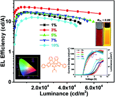
Introduction
Organic light-emitting diodes (OLEDs) have become a hot research field and have attracted great attention due to their potential applications in organic flat-panel displays since Tang reported efficient electroluminescence by using tris(8-hydroxyquinolinato) aluminium (AlQ3) as an emitter in the first efficient small molecule OLEDs in 1987.1 The organic electrophosphorescent materials play a critical role because they can fully utilize both singlet and triplet excitons through the strong spin-orbital coupling caused by heavy metal ions in complexes. Theoretically, the internal quantum efficiency of the phosphorescent OLEDs (PhOLEDs) can reach up to 100%.2 Among these emitting materials for OLEDs, iridium(III) complexes are the most promising candidates. Iridium(III) complexes are usually constituted by three bidentate ligands, either homoleptic (C^N)3Ir or heteroleptic (C^N)2Ir(L^X), where C^N represents a cyclometalating bidentate ligand and L^X stands for an ancillary bidentate ligand.3 In general, the cyclometalating ligands (C^N) are usually aromatic heterocyclic rings containing C, N, S, O atoms, etc.4 Aromatic heterocyclic compounds containing N atoms such as pyrimidine derivates and pyridine derivates are expected to be electron-deficient units which have been used to construct novel cyclometalated organic ligand and electron-transporting materials.5 In 2003, Tsuboyama et al. designed and synthesized a series of neutral facial homoleptic cyclometalated iridium(III) complexes based on pyridine derivates cyclometalating ligands (C^N) for use as red-emissive materials in OLEDs.6 Cyclometalated organic ligands containing pyrimidine unit has high electron affinities and may possibly afford iridium(III) complexes with high quantum efficiency.7 These pyrimidine-based iridium(III) complexes have better properties than pyridine-based iridium(III) complexes, so iridium(III) pyrimidine complexes have attracted much attention for their high device performances in the past decade.5,8–11 Some new iridium(III) complexes using 2-substituted pyrimidine derivatives as the cyclometalated ligands were synthesized.5,8,9 Chang et al. designed 5-substituted pyrimidine chelates and the corresponding iridium complexes. With this new phosphor design, the best phosphorescent OLED exhibited a peak external quantum efficiency of 17.9%, a luminance efficiency (LE) of 38.0 cd A−1.10 Jiang et al. used 4,6-disubstituted pyrimidine derivatives as the cyclometalated ligands and synthesized pyrimidine-based iridium(III) complexes with high quantum efficiency.11 Among these pyrimidine-based iridium(III) complexes, ancillary ligands (L^X) are usually containing C, N, O atoms and the most common auxiliary ligands are acetylacetone (acac, L^X
O^O), 2-pyridinecarboxylic acid (pic, L^X
N^O) and 2,2′-bipyridine (bipy, L^X
N^N). Sulfur atoms are rarely introduced into the auxiliary ligands for the iridium complexes used in OLEDs. In recently, the selection of ancillary chelates has been extended to the less accessible, tailor-made heterocycles such as dithiocarbamate, dithiophosphate, and benzamidinate. Dithiolate compounds are very stable that can reduce the work function of the emitter and reduce the threshold electric field, therefore reducing the turn on voltage.12 Iridium(III) complexes (TPQ)2Ir(Et2dtc) and (TPQ)2Ir(Et2dtp) used dithiolate (S^S) as the ancillary ligand were synthesized, but two complexes showed low photoluminescence quantum efficiencies of only 8.4% and 3.2%, respectively.12,13 In this paper, a highly efficient phosphorescent iridium(III) complex Ir(dpp)2(dta) with diethyldithiocarbamate (S^S) as the ancillary ligand was successfully designed and synthesized with emission ranged at 575 nm and high photoluminescence quantum yield of 86%. We used Ir(dpp)2(dta) as a triplet emitter doped in a polymeric host (70% PVK: 30% OXD-7) in solution-processed method and prepared yellow-orange OLED. When the doping density was 3%, the device achieved the maximum luminance of 81
918 cd m−2, the highest EL efficiency of 30.12 cd A−1 and the external quantum efficiency of 9.28%.
Results and discussion
Synthesis and characterization
As shown in Scheme 1, the cyclometalated ligand 4,6-diphenyl pyrimidine was conveniently prepared by 4,6-dichloro-pyrimidine and phenyl-boronic acid in the toluene solvent according to the Suzuki procedures. The reaction was at 120 °C for 24 h and the yield of products was satisfactory. The synthesis of the iridium(III) complex Ir(dpp)2(dta) included two steps. First, the cyclometalated Ir(III) μ-chloride bridged dimer was synthesized by reacting IrCl3·3H2O with the cyclometalated ligand at 125 °C for 24 h under nitrogen. Then, the chloride-bridged dimer was reacted with sodium diethyldithiocarbamatodithioate in dichloromethane (CH2Cl2) solution to afford the target products in 60% yields. The structures of these products were confirmed by NMR and mass.
 |
| Scheme 1 Synthesis of Ir(dpp)2(dta). | |
The X-ray crystallography of Ir(dpp)2(dta)
Single crystal of Ir(dpp)2(dta) suitable for X-ray diffraction analysis has been grown by slow diffusion of hexane into a dichloromethane solution of the complex. ORTEP drawing of the structure is shown in Fig. 2, and selected crystallographic data are provided in Table S1† and the bond lengths [Å] and angles [deg] for Ir(dpp)2(dta) are listed in Table S2.† The complex has the expected octahedral coordination geometry around the iridium center by two cyclometalated ligands 4,6-diphenyl pyrimidine and one ancillary ligand diethyl dithiocarbamic acid sodium salt (dta) with the cis-C,C and trans-N,N chelating disposition of the original chloro-bridged dimer as reported in related examples.14 The Ir–C bond lengths are shorter than the Ir–N bond distances as shown in Table S2.† This result implies that there is a stronger trans influence of the phenyl group over that of the 4,6-diphenyl pyrimidine. The two coordinated S atoms of ancillary ligand reside in the equatorial plane trans to the metalated C (dpp) atoms.
 |
| Fig. 1 General structure for the OLED devices and molecular structures of the relevant compounds. | |
 |
| Fig. 2 Perspective view of Ir(dpp)2(dta). | |
UV-vis absorption and photoluminescence properties
The absorption and the photoluminescence spectra of the complex Ir(dpp)2(dta) in CH2Cl2 solution at room temperature were shown in Fig. 3. The strong absorption bands at 303 nm and 402 nm were assigned to the spin-allowed 1π–π* transition. In addition, the weak and broad absorption band at 510 nm can be attributed to the typical spin-allowed and spin-forbidden metal-to-ligand charge transfer bands (MLCT). It can be found that the MLCT absorption bands of Ir(dpp)2(dta) were mostly covered by the emission band of host material (PVK: OXD-7 blend λmax = 320 nm). It indicated that the Förster energy can transfer from the singlet-excited states of the host to the MLCT states of the iridium(III) complex Ir(dpp)2(dta) effectively. PL spectrum of Ir(dpp)2(dta) in CH2Cl2 solution showed a strong yellow-orange phosphorescent emission at 575 nm. The phosphorescence emission of the Ir(dpp)2(dta) complex was found to mainly originate from the 3MLCT (metal-to-ligand charge transfer) excited states and/or the ligand-centered (LC) 3π–π* excited states.15 Moreover, the absolute quantum efficiencies (Φ) of Ir(dpp)2(dta) in solid power and doped PMMA were measured. All data of the photophysical properties were listed in Table S3.† The Φpower and Φfilm (in 1% PMMA film) were 14% and 86%, respectively. As showed in Fig. S7,† the phosphorescent life time of Ir(dpp)2(dta) in film was 0.904 μs.
 |
| Fig. 3 UV-vis absorption and photoluminescence spectra of Ir(dpp)2(dta) at the solution of CH2Cl2. | |
Electrochemical properties
The electrochemical properties of the iridium(III) complex Ir(dpp)2(dta) was investigated by cyclic voltammetry in CH2Cl2 solution at room temperature using ferrocene as the internal standard. The conventional three-electrode cell with a Pt work electrode of 2 mm diameter, a platinum-wire counter electrode, and a Ag/AgCl reference electrode was employed. The scan rate is 0.1 V s−1. At the end of the experiment, the ferrocene/ferricenium (Fc/Fc+) couple was used as the internal standard as shown in Fig. S8.† The HOMO energy levels (eV) of the complex is calculated according to the formula: −[4.8 + (Eox1/2 − E1/2(Fc/Fc+))] eV. The half-wave oxidation potential (Eox1/2) is 0.9 V vs. Ag/AgCl as shown in Fig. S9.† The highest occupied molecular orbital (HOMO) energy level was calculated to be −5.28 eV. The energy gap (Eg) derived from the UV-vis absorption band, calculated according to the formula: 1240/λabs. Finally, the lowest unoccupied molecular orbital (LUMO) energy level was calculated according to the formula: HOMO + Eg, and to be −3 eV. It is clear that the HOMO and LUMO levels of the complex are exactly between the HOMO and LUMO levels of PVK (HOMO = −5.8 eV and LUMO = −2.2 eV). So the iridium(III) complex Ir(dpp)2(dta) can trap both electrons and holes, and resulted in high device efficiency.
Theoretical calculations
To compare the experimentally obtained HOMO/LUMO levels with the theoretical calculation, we have used the B3LYP density functional theory (DFT) to calculate HOMO/LUMO energy levels and the electronic ground states for (dfppy)2Ir(LN^O).16
As shown in Table 1 and 2, it is obvious that the LUMO of Ir(dpp)2(dta) is locates in diphenyl pyrimidine. However the HOMO of Ir(dpp)2(dta) distributes in Ir and cyclometalated ligand. The energy transfer consists
MLCT,
LLCT and 3LC
, especially between their mixed valence.
Table 1 Energy levels of Ir(dpp)2(dta)
Molecule |
LUMOcal |
HOMOcal |
Eg[cal] |
Transition |
Ir(dpp)2(dta) |
−1.8776 |
−5.0886 |
3.211 |
LC/MLCT/LLCT |
Table 2 Electronic ground states of Ir(dpp)2(dta)
Molecule |
LUMO |
HOMO |
Ir(dpp)2(dta) |
 |
 |
Thermal properties
The thermal properties of the iridium complex was examined by thermal gravimetric analysis (TGA) under an N2 atmosphere at a heating rate of 10 °C min−1 from room temperature to 700 °C. The results in Fig. 4 suggested that Ir(dpp)2(dta) exhibited good thermal stability properties with high decomposition temperatures (Td, corresponding to 5% weight loss) of 215 °C, which was beneficial to the long-term stability of the OLED devices fabricated from these materials.
 |
| Fig. 4 TG curves of iridium complexes. | |
Electrophosphorescent properties
To investigate the EL properties of the iridium(III) complex Ir(dpp)2(dta), the PLEDs using Ir(dpp)2(dta) as dopant with the device structure of ITO/PEDOT:PSS (40 nm)/(70% PVK + 30% OXD-7): x% Ir(dpp)2(dta) (70 nm)/TPBI (30 nm)/Ca (15 nm)/Ag (100 nm) were fabricated. Fig. 1 shows the general structure and molecular structure of the compounds used in the devices. Indium tin oxide (ITO) on a substrate of electroluminescent device is the anode and Ca/Ag as the cathode. PEDOT/PSS as hole injection layer can smooth the ITO surface, reduce the probability of electrical shorts, decrease the turn-on voltage and prolong the operation lifetime of the device. PVK:OXD-7 blend can be used as host materials, and TPBI as the hole-blocking material can improve electron injection and electron transport. In the emitting layer, the doping concentrations of Ir(dpp)2(dta) were 1%, 3%, 5%, 7% and 10%, respectively. The doping concentrations of Ir(dpp)2(dta) were according to the host and the mass ratio of OXD-7 was 30% in the PVK:OXD-7 blend.
The HOMO/LUMO levels of the materials used in PLEDs were described in Fig. 1. The PVK:OXD-7 blend material with high HOMO levels as electron-donating and hole-transport media, while TPBI with low LUMO levels as electron-accepting and electron-transport media. Hole was injected from the anode to HOMO levels of host material and electron was injected in LUMO levels. The HOMO and LUMO level of Ir(dpp)2(dta) was embedded between the HOMO of PVK (−5.80 eV) and its LUMO (−2.20 eV). Thus, efficient energy transfer to Ir(dpp)2(dta) occured in the emitting layer (EML). The PLED performance in luminance should be determined by the intrinsic quantum efficiency of Ir(dpp)2(dta) in radiative decay. Because the HOMO level of Ir(dpp)2(dta) was 0.52 eV higher than that of PVK, it behaved as effective trapping sites for holes; meanwhile, the LUMO level of Ir(dpp)2(dta) was 0.8 eV lower than that of PVK, electrons injected from the TPBI layer into the emitting layer were mostly transported through the PVK layer and being composited in the iridium phosphor. Thus, varying the concentration of Ir(dpp)2(dta) in the EML should significantly alter the degree of charge injection in PVK-based devices. Therefore, the current density of the PVK-based devices exhibited a strong dependence on the doping concentration.
The normalized electroluminescence (EL) spectra of Ir(dpp)2(dta) doped PVK:OXD-7 devices in the doping concentrations from 1% to 10% at 8 V are shown in Fig. 5, while others such as 6 V, 10 V and 12 V are in the ESI in Fig. S11.† We noticed that there are weak emission peaks at about 420 nm from the host PVK:OXD-7 in 1% doping concentration. Then the peak decreased with an increase in doping concentration and finally disappeared with increasing doping concentration to 3%. It can be speculated that the energy is complete transfer from host to Ir(dpp)2(dta) in higher doping concentration. But for the PL spectra for different doping concentrations (Fig. S10†), even at the doping concentration of 7%, complete quenching of the PVK:OXD-7 emission is not observed. This implies that energy transfer from the PVK:OXD-7 blend to the iridium complex is inefficient under photo-excitation. The phenomenon with complete quenching of the host EL emission in higher doping concentration (5–10%) indicating that excitons in the dopants formed both by direct charge trapping in the dopant molecules and energy transfer from the host to Ir(dpp)2(dta) is efficient under electrical excitation. So the doping concentrations have significant influence on the mixing single and triplet emission of MLCT. EL spectra with peaks at about 575 nm are observed in all of the devices. Meanwhile, with doping concentration increasing, the EL spectra are steadily and the CIE plot were located in the Fig. S13.† The Commission International del'Eclairage (CIE) color coordinate is (0.4745, 0.5109) which is almost closed to the standard yellow demanded by the National Television System Committee (NTSC). Fig. 6 present selector luminescence spectra of device (3%) at different voltage, while others such as 1%, 5%, 7%, 10% are in the Fig. S12 in ESI.† With the change of voltage from 6 V to 12 V, the spectrum is almost unchanged and there are no residual emissions from the host even at high voltage. It can be indicated that the device had a good light-stability. Fig. 7 shows current density and luminance vs. voltage curves of Ir(dpp)2(dta) doped OLEDs from 1% to 10% doping concentrations. The device at 3% doping concentration achieved the maximum luminance, reaching 81
918 cd m−2.
 |
| Fig. 5 EL spectra of different devices at 8 V. | |
 |
| Fig. 6 EL spectra of the device (3%) at different voltage. | |
 |
| Fig. 7 Current density–voltage–luminance curves of the devices. | |
The maximum external quantum efficiency and the maximum luminous efficiency of the device at 3% doping concentration are 9.28% (Fig. S14†) and 30.12 cd A−1 (Fig. 8), respectively. The EL device with a traditional EL structure shows no obvious efficiency roll-off even at high luminance and the EL efficiency decrease by 7.8% of its maximum upon 20
000 cd m−2 (Table 3). The extra-high efficiency is an indication of balanced electron and hole recombination in the host matrix, and complete energy and charge transfer from the host material to iridium(III) complex upon electrical excitation. The devices showed no obvious differences in turn-on voltage with increasing doping concentration from 1% to 10%. In order to investigate the performances of these electrophosphorescent devices with different doping concentrations, the parameters of these devices were summarized in Table 3. The best device performance was obtained in the device 2 at 3% doping concentration.
 |
| Fig. 8 EL efficiency–luminance of the devices. | |
Table 3 Performances of the electrophosphorescent devices
Device |
Turn-on voltage (V) |
Lmax (cd m−2) |
The maxima of quantum efficiency |
CIE (x, y) |
EQE (%) |
LE (cd A−1) |
Roll-off (%) at 20 000 cd m−2 |
Voltage (V) |
CD (mA cm−2) |
L (cd m−2) |
1(1%) |
4 |
49 804.6 |
6.16 |
20.35 |
13.12 |
7.68 |
51.77 |
10 535.4 |
(0.4577, 0.5088) |
2(3%) |
4.1 |
81 918.0 |
9.28 |
30.12 |
7.8 |
8.0 |
28.18 |
8488.9 |
(0.4745, 0.5109) |
3(5%) |
4.1 |
59 649.8 |
6.02 |
19.89 |
4.43 |
7.09 |
49.9 |
9923.4 |
(0.4792, 0.5074) |
4(7%) |
4 |
55 064.3 |
6.64 |
21.01 |
4.81 |
6.79 |
44.34 |
9318.0 |
(0.4801, 0.5086) |
5(10%) |
3.9 |
46 857.1 |
4.61 |
13.95 |
6.81 |
6.8 |
98.40 |
13 726.3 |
(0.4787, 0.5035) |
Conclusions
In summary, we designed and synthesized a new iridium(III) complex by introducing the 4,6-diphenylpyrimidine on the frame of Ir(dpp)2(dta) to develop highly efficient yellow phosphors. In addition, the Ir(dpp)2(dta)-based device 2 still possessed high EL efficiency of 30.12 cd A−1, maximum luminance of 81
918.0 cd m−2 and EQE of 9.28% at extremely high luminance of 8488.9 cd m−2. To the best of our knowledge, this efficiency was a higher ever reported for vacuum-deposited yellow PhOLEDs.
Experimental
The synthesis of Ir(dpp)2(dta)17
A mixture of 4,6-dichloro-pyrimidine (0.3 g, 2 mmol), phenyl-boronic acid (1.08 g, 4 mmol), Pd(pph3)4, TBAB, toluene (10 mL) and 2 M K2CO3 (10 mL) were stirred at 120 °C for 24 h under nitrogen. Then the reaction mixture was cooled to room temperature, and followed poured into 200 mL water extracted by ethyl acetate. The organic layer was washed with water and dried over anhydrous Mg2SO4. After filtration, the solvent was removed under reduced pressure. The residue was purified by column chromatography (petroleum ether/ethyl acetate (6
:
1) as eluent) to afford 4,6-diphenyl pyrimidine, yield = 80%, mp = 80 °C. 1H NMR (400 MHz, CDCl3) δ 9.33 (s, 1H), 8.14 (dd, J = 13.2, 9.4 Hz, 5H), 7.59–7.50 (m, 6H). 13C NMR (CDCl3, 100 MHz) δ: 164.73, 159.23, 137.05, 130.97, 129.06, 127.22, 112.86. GC-MS (m/z): 232.
A mixture of IrCl3·3H2O (0.70 g, 2 mmol) and 4,6-diphenylpyrimidine (1.16 g, 5 mmol) were added in a mixture of 2-methoxyethanol 12 mL and distilled water 4 mL. The mixture was stirred at 125 °C for 24 h under nitrogen. After cooled to room temperature, the precipitate was collected by filtration and washed with water and ethanol, gave to the dimeric iridium(III) complex [(dpp)2IrCl]2. After drying, the crude product was directly used for next step without further purification. Cyclometalated [(dpp)2IrCl]2 (1.38 g, 1 mmol), K2CO3 (1.38 g, 10 mmol) and 5 equivalents of diethyl dithiocarbamic acid sodium salt in dichloromethane (10 mL) was stirred at room temperature under a nitrogen atmosphere for 3 h. After reaction, the mixture solution was distilled under vacuum. The crude product was purified by column chromatography over aluminum oxide using dichloromethane/petroleum ether as the eluent to afford the desired iridium(III) complex Ir(dpp)2(dta) (4.8 mmol, 2.8 g). Yield: 60%. 1H NMR (400 MHz, CDCl3) δ: 10.24 (d, J = 0.9 Hz, 2H), 8.27 (dd, J = 8.0, 1.3 Hz, 4H), 8.19 (d, J = 0.8 Hz, 2H), 7.81 (dd, J = 7.8, 0.9 Hz, 2H), 7.64–7.53 (m, 6H), 6.88 (dd, J = 7.6, 1.0 Hz, 2H), 6.82 (dd, J = 7.5, 1.2 Hz, 2H), 6.62–6.54 (m, 2H), 3.76–3.70 (m, 2H), 3.62–3.46 (m, 2H), 1.25 (d, J = 4.8 Hz, 6H). 13C NMR (CDCl3, 100 MHz) δ: 175.17, 162.75, 160.44, 159.96, 144.73, 136.23, 132.42, 131.37, 130.92, 129.05, 127.51, 125.62, 121.19, 109.03, 43.78, 12.40. HRMS (+TOF): m/z = 804.1818 (calcd 804 for [C37H32N3S2Ir], [M]+).
Acknowledgements
The authors acknowledge financial support from the National Basic Research Program of China (973 Program, 2012CB933301, 2012CB723402), the Ministry of Education of China (IRT1148), the National Natural Science Foundation of China (BZ2010043, 20974046, 20774043, 51173081, 50428303, 61106017, 61136003), the Priority Academic Program Development of Jiangsu Higher Education Institutions (PAPD, YX03001), Jiangsu National Synergistic Innovation Center for Advanced Materials (SICAM), the Nature Science Foundation of Jiangsu Province (BK20131375) and the Research Fund for Nanjing University of Posts and Telecommunications (NY215153).
Notes and references
- C. W. Tang and S. A. VanSlyke, Appl. Phys. Lett., 1987, 51, 913 CrossRef CAS; M. A. Baldo, M. E. Thompson and S. R. Forrest, Nature, 1998, 395, 151 CrossRef.
- M. A. Baldo, S. Lamansky, P. E. Burrows, M. E. Thompson and S. R. Forrest, Appl. Phys. Lett., 1999, 75, 4 CrossRef CAS.
- B. W. D'Andrade and S. R. Forrest, Adv. Mater., 2004, 16, 1585 CrossRef.
- C. Fan and C. Yang, Chem. Soc. Rev., 2014, 43, 6439 RSC.
- C. F. Lin, W. S. Huang, H. H. Chou and J. T. Lin, J. Org. Chem., 2009, 694, 2757 CrossRef CAS.
- A. Tsuboyama, H. Iwawaki, M. Furugori, T. Mukaide, J. Kamatani, S. Igawa, T. Moriyama, S. Miura, T. Takiguchi, S. Okada, M. Hoshino and K. Ueno, J. Am. Chem. Soc., 2003, 125, 12971 CrossRef CAS PubMed.
- C. L. Ho, W. Y. Wong, G. J. Zhou, B. Yao, Z. Y. Xie and L. X. Wang, Adv. Funct. Mater., 2007, 17, 2925 CrossRef CAS.
- G. P. Ge, J. He, H. Q. Guo, F. Z. Wang and D. C. Zou, J. Org. Chem., 2009, 694, 3050 CrossRef CAS.
- Z. Q. Wang, C. Xu, X. M. Dong, Y. P. Zhang, X. Q. Hao, J. F. Gong, M. P. Song and B. M. Ji, Inorg. Chem. Commun., 2011, 14, 316 CrossRef CAS.
- C. H. Chang, Z. J. Wu, C. H. Chiu, Y. H. Liang, Y. S. Tsai, J. L. Liao, Y. Chi, H. Y. Hsieh, T. Y. Kuo, G. H. Lee, H. A. Pan, P. T. Chou, J. S. Lin and M. R. Tseng, ACS Appl. Mater. Interfaces, 2013, 5, 7341 Search PubMed; J. S. Park, Y. G. Park, J. Y. Lee, J. W. Kang, J. Liu and S. H. Jin, Org. Electron., 2013, 14, 2114 CrossRef CAS; F. L. Zhang, W. L. Li, Y. M. Jing, D. X. Ma, F. Q. Zhang, S. Z. Li, G. G. Cao, G. Guo, B. Wei, D. P. Zhang, L. Duan, C. Y. Li, Y. F. Feng and B. Zhai, J. Mater. Chem., 2016 10.1039/c6tc01041e.
- L. S. Cui, Y. Liu, X. Y. Liu, Z. Q. Jiang and L. S. Liao, ACS Appl. Mater. Interfaces, 2015, 7, 11007 CAS.
- D. Q. Gao, F. Scholz, H. G. Nothofer, W. E. Ford, U. Scherf, J. M. Wessels, A. Yasuda and F. V. Wrochem, J. Am. Chem. Soc., 2011, 133, 5921–5930 CrossRef CAS PubMed; Y. Liu, K. Ye, Y. Fan, W. Song, Y. Wang and Z. Hou, Chem. Commun., 2009, 25, 3699 RSC; T. Peng, H. Bi, Y. Liu, Y. Fan, H. Gao, Y. Wang and Z. Hou, J. Mater. Chem., 2009, 19, 8072 RSC.
- L. Q. Chen, H. You, C. L. Yang, X. W. Zhang, J. G. Qin and D. G. Ma, J. Mater. Chem., 2006, 16, 3332 RSC; L. Q. Chen, C. L. Yang, J. G. Qin, J. Gao, H. You and D. G. Ma, J. Organomet. Chem., 2006, 691, 3519 CrossRef CAS; L. Q. Chen, C. L. Yang, J. G. Qin, J. Gao and D. G. Ma, Synth. Met., 2005, 152, 225 CrossRef.
- S. Lamansky, P. Djurovich, D. Murphy, F. Abdel-Razzaq, R. Kwong, I. Tsyba, M. Bortz, B. Mui, R. Bau and M. E. Thompson, Inorg. Chem., 2001, 40, 1704 CrossRef CAS PubMed; A. J. Hallett, B. D. Ward, B. M. Kariuki and S. J. A. Pope, J. Organomet. Chem., 2010, 695, 2401 CrossRef.
- I. M. Dixon, J. P. Collin, J. P. Sauvage, L. Flamigni, S. Encinas and F. Barigelletti, Chem. Soc. Rev., 2000, 29, 385 RSC.
- D. R. Whang, Y. You, S. H. Kim, W. L. Jeong, Y. S. Park, J. J. Kim and S. Y. Park, Appl. Phys. Lett., 2007, 91, 233501 CrossRef CAS; L. L. Shi, J. J. Su and Z. J. Wu, Inorg. Chem., 2011, 50, 5477 CrossRef PubMed; L. L. Shi, B. Hong, W. Guan, Z. J. Wu and Z. M. Su, J. Phys. Chem. A, 2010, 114, 6559 CrossRef PubMed; X. N. Li, Z. J. Wu, Z. J. Si, H. J. Zhang, L. Zhou and X. J. Liu, Inorg. Chem., 2009, 48, 7740 CrossRef PubMed; J. H. Jou, Y. X. Lin, S. H. Peng, C. J. Li, Y. M. Yang, C. L. Chin, J. J. Shyue, S. S. Sun, M. Lee, C. T. Chen, M. C. Liu, C. C. Chen, G. Y. Chen, J. H. Wu, C. H. Li, C. F. Sung, M. J. Lee and J. P. Hu, Adv. Funct. Mater., 2014, 24, 555 CrossRef.
- Q. B. Mei, Y. H. Guo, B. H. Tong, J. N. Weng, B. Zhang and W. Huang, Analyst, 2012, 137, 5398 RSC.
Footnote |
† Electronic supplementary information (ESI) available: Experimental details, structure characterization data of the ligands and iridium complexes synthesized in this work, cyclic voltammogram and computational details. CCDC 1402238. For ESI and crystallographic data in CIF or other electronic format see DOI: 10.1039/c6ra12529h |
|
This journal is © The Royal Society of Chemistry 2016 |
Click here to see how this site uses Cookies. View our privacy policy here.