Yu-Chuan Shih,
Tsang-Hsuan Wang,
Jian-Shiou Huang,
Chih-Chung Lai,
Ying-Jhan Hong and
Yu-Lun Chueh*
Department of Materials Science and Engineering, National Tsing Hua University, Hsinchu, 30013, Taiwan, Republic of China. E-mail: ylchueh@mx.nthu.edu.tw
First published on 3rd June 2016
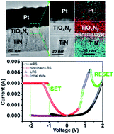
A TiOxNy thin film, which contains controllable concentrations of oxygen and nitrogen by a single-step reactive sputtering process using a non-symmetric Pt electrode as top electrode and TiN as bottom electrode, exhibiting non-linear I–V behavior, was proposed and demonstrated. A switching model of the non-linear I–V switching was built based on diffusion of oxygen vacancies in the TiOxNy film with different ratios of O and N after the SET process. Effects on the switching relationship between TiOxNy and electrodes were investigated to optimize the best conditions for the non-linear behavior. The origin of the nonlinear property was investigated in detail by changing the compositions of oxygen and nitrogen in the TiOxNy thin film. We believe that these findings would open up opportunities to exploit resistive switching mechanisms and simple memristor stacking in next generation crossbar array applications.
To solve this problem, a memristor combined with the selective devices such as diodes, selectors, or switching devices is necessary.8,10,11 Recently, a concept of complementary resistive switching (CRS), namely non-linear I–V behavior, was proposed as another pathway to mitigate the sneak path issue by anti-serially connecting two devices together.9,12 In addition, some researches have also proposed CRS devices with direct symmetry stacking.13 Either the combination of the selective device or the concept of CRS makes the fabrication of the memristor more complicate so that the memristor may lose the advantage of its simple structure. Besides, it is also difficult to realize a vertically stacking structure. As a result, the development of the memristor with the non-linear behavior and the simple structure is imperative.14
In this regarding, a TiOxNy thin film, which contains controllable concentrations of O and N by a single-step reactive sputtering process using non-symmetric electrode Pt as top electrode and TiN as bottom electrode, exhibiting a non-linear I–V behavior in order to suppress the sneak path issue, was proposed and demonstrated. The influence of the non-linear behavior for the TiOxNy film with different concentrations of N and O were examined in terms of microstructures and chemical bonding by transmission electron microscope (TEM) and X-ray absorption spectrometer (XPS), systematically. Effects on switching relationship between TiOxNy and electrodes were discussed to optimize the best condition of the non-linear behavior. We found that the obvious non-linear behaviors can be achieved for the TiOxNy film with x = 6 and y = 16.7% and a ratio of Ion/Ioff upto 102. A switching model of the non-linear I–V switching was built based on diffusion of oxygen vacancies in the TiOxNy film with ratio changes between O and N after the SET process. The changeable compositions of the TiOxNy film makes this process more promising as the memristor for the possible application on crossbar arrays with a high density storage capacity.
To understand the origin of the non-linear resistance states, we change concentrations of O from 3 to 40%, while keeping concentration of N at 16.7%, the same in the TiOxNy film with the same electrical measurement condition. I–V curves and endurance tests were measured and showed in Fig. S1.† Fig. 2a shows the cumulative probability of the resistive switching at 0.5 V. Note that with the higher oxygen concentration, the HRS increases due to compensation of oxygen vacancies, resulting in the increase of the ON/OFF ratio. The same trend can be observed even at 1.0 V (Fig. S1†). Only the linear LRS was observed in devices with 3% O concentrations (Fig. S1†), while the non-linear LRS was found in the higher O concentration. Furthermore, the portion of non-linear LRS also increases with the increasing O concentrations in the TiOxNy from 6 to 16.7%.This phenomenon can be confirmed after measuring at least 20 devices for each condition as showed in Fig. 2b. The non-linear probability is defined as cycles of non-linear behaviors to 100 switching cycles. However, the continuous distribution of the LRS at 0.5 V can be found as the oxygen concentration reaches to 40% and would increase the probability of the sneak path issue because the total resistance of the cells on the shortest sneak path is still significantly small. Another factor is the reduction of the yield from 86% to 60% once O concentrations in the TiOxNy increase from 16.7 to 40%, resulting in hard breakdown of device more easily after the forming process. As the result, the optimized O concentration can be found with oxygen concentration ranging from 6 to 16.7%, especially near 16.7%, with appropriate resistance values and stable endurance performance.
Furthermore, effects of different electrodes were also investigated under the best O concentration. The corresponding I–V behaviors in Fig. S2a† clearly show that no non-linear behavior in the LRS can be observed in the symmetry Pt/TiOxNy/Pt stacking. However, the non-linear I–V behavior still exists ever if we switch the original stacking of top and bottom electrodes from Pt/TiOxN/TiN into TiN/TiOxNy/Pt with the applied inverse bias polarity. From this point, it can be considered that the interface of TiOxNy/TiN or TiN/TiOxNy indeed plays the critical role of the nonlinear LRS. From the experimental results, in spite of the same electrodes and insulating layer, the non-linear behavior is only shortly appeared in the TiN/TiOxNy/Pt devices. The device with TiN as bottom electrode showed repeated non-linear behavior while the Pt bottom only showed the non-linear behavior in the first few cycles. To explain this difference, the sputtering process during the deposition of the TiOxNy film was taken into account. During the sputtering process, the particles from the Ti target would bombard the substrate and it will be more obvious at the high power. With the Pt electrode as the bottom electrode, the O and N would not interact with the Pt electrode during the sputtering process. However, an interfacial layer on top of TiN electrode during the sputtering process of the TiOxNy film will be spontaneously formed, which largely influences the behavior of ReRAM characteristics.15,16 To confirm the importance of the interfacial layer between TiOxNy/TiN, the distribution of the LRS, nonlinear LRS and HRS are further collected by measuring devices with different electrodes in diameter (different electrode areas) from 50, 100 and 200 μm as shown in Fig. 2c. The LRS still reminds with different electrode areas, while the nonlinear LRS and HRS increase with the decrease of electrode areas. The retention was also conducted for different states as shown in Fig. 2d. Only the nonlinear LRS can be read at the half of read voltage (0.5 V), being different from others obtained at the read voltage of 1 V. Note that all states can keep its initial value for at least 103 seconds without any degradation. By taking the distribution of LRS and HRS in Fig. 2c into account, no resistance change with different electrode areas in LRS matches the filamentary resistive switching that the oxygen vacancies accumulate in the bulk of the TiOxNy layer. However, for nonlinear LRS and HRS, it shows the homogeneous characteristic due to the existence of an interfacial layer, meaning the homogenous-dominated switching mechanism.17 As a result, the current jumps up in the LRS indicating the changes of switching mechanism from homogenous-dominated to filamentary-dominated switching and the formation of the interfacial layer is affected by the amount of the oxygen ions in the TiOxNy thin film.
To confirm the existence of the interfacial layer, material analyses such as transmission electron microscope (TEM) and electron energy loss spectrometer (EELS) mapping images were investigated in order to shed light on the sputtering effect as shown in Fig. 3. Note that due to the similar atomic mass of nitrogen and oxygen, it is hard to find different contrast between TiN and TiOxNy layers by a bright field image as shown in Fig. 3a and b where the boundary was not obvious and could only be distinguished by the different crystallization, namely polycrystalline TiN and amorphous TiOxNy crystalline structures. To shed light on different distribution between O and N, EELS mapping images were used as shown in Fig. 3c, with which the white dashed line was added to indicate the boundary between two layers. Note that the red dots are referred to O atoms and the light blue ones are referred to N atoms. By using different colors to represent different elements, a clear distribution of O and N throughout two layers can be observed. Clearly, a region containing a signal of O and N “mixed together”, namely a mixed layer (interfacial layer) between TiN and TiOxNy layers, exists (Fig. 3c). Compared with the top electrode Pt and TiOxNy film, no mixed layer can be found, confirmed that the interfacial layer was spontaneously formed during the sputtering process.16
To further investigate roles of N concentrations during switching behaviors, we changed N concentrations during sputtering processes. Here, the O concentration was fixed at 16.7% while N concentrations were changed from 0 to 40%. Besides, the total gas flow was still fixed as the previous cases. The corresponding switching characteristics are shown in Fig. 4a. Obviously, typical I–V behaviors do not vary very much with different oxygen concentrations. These devices could be operated under the same condition as before, including the same SET/RESET voltages (−1 to −2 V/1–1.5 V), current compliance (3 mA) and operation along the clockwise direction. Although, the non-linear behavior could be also observed, it showed significantly different distribution in the cumulative probability as shown in Fig. 4b. In LRS with the higher N concentration, the distribution of resistance is more uniform, meaning that the nonlinearity can be suppressed. The switching behavior is similar to the typical linear resistive switching behavior with only a few cycles of non-linear behaviors in the TiOxNy film at the N concentration of 40%, while the resistive switching shows distinct non-linear behavior using the TiOxNy thin film without N, namely TiOx. The results indicate no benefit for insertion of N atoms into the TiOxNy film to enhance the nonlinear behavior. However, N atoms can actually stabilize the RS behavior during the operation, especially in HRS as shown in Fig. 4b where the distribution of HRS without N has a large variation from 5 × 10³ to 105 Ω, overlapping with the region of the nonlinear LRS and resulting in faults during the readout process. After N concentration reaches to 40% (TiOxNy film), the HRS is very stable, exhibiting a straight line in cumulative probability plots. Furthermore, the HRS becomes smaller as the N concentration increases. It can be believed that the resistive switching phenomenon is mainly related to the distribution of the oxygen ions/vacancies in the TiOxNy film due to the lack of the active metal as electrodes such as Ag or Cu. Thus, controlling of oxygen ions/vacancies concentrations in the TiOxNy film plays an important role in operating the memristor. Huang et al. reported that the addition of N into the oxide film would increase the proportion of oxygen vacancies, resulting in decrease of both HRS and LRS as the N concentration increases.18 However, higher ions/vacancies concentrations would form uniform conducting filaments so that the resistive switching behavior would be linear gradually, with which the nonlinear LRS only appeared as O ions/vacancies partially accumulated at the bottom interface. As a result, controlling the composition between oxygen and nitrogen is imperative for high density device application in future.
To further confirm that the insertion of N atoms may affect the formation and elimination of O ions/vacancies, the bonding information of the TiOxNy film with different N concentrations were investigated by XPS. Fig. 5a and b show the bonding energies of Ti 2p2/3 and N 1s spectra for the TiOxNy films at different N concentrations.19–21 Note that Ti and N peaks change as the N concentrations increase. In Fig. 5a, a peak appears with a shoulder of the Ti 2p2/3 peak when N concentration increases to 40%. It can be served as the increase of the bonding energy between the Ti and N atoms. Similar results can also be found in N peak as shown in Fig. 5b. Obviously, the N 1s peak changes from the higher bonding energy (∼399 mV) to lower bonding energy (396 mV), compared with no-nitrogen one as N concentrations increases. It means that the bonding statuses of N atoms change from O–N in TiN coating (399 mV) to TiNO species (396 mV),22 owing to formation of oxynitride (TiOxNy) as the concentration of N increases. To further confirm the formation of the TiOxNy film at the N concentration of 40%, we fitted the Ti 2p peaks into three possible bonding types, namely TiO2, Ti–O suboxide and TiOxNy peaks, respectively as shown in Fig. 5c. Clearly, strong intensities of TiOxNy and Ti–O suboxide could be distinctly observed, confirming the high concentrations of oxygen ions/vacancies due to the formation of TiOxNy or Ti–O suboxide. Note that the strongest peak is still contributed to TiO2 even increasing the N concentration up to 40% due to the lowest formation energy of TiO2 than nitride or oxynitride.
![]() | ||
Fig. 5 (a) XPS spectra of (a) Ti peaks (b) N peaks at different N concentrations. (c) Detailed fitting of Ti peaks for the TiOxNy film at the N composition of 40%. |
From the material analyses and experimental results, a suitable and reasonable models of the unusual I–V behaviors can be proposed. When firstly applying a negative voltage on the devices, it is needed a larger voltage to make the resistance switching, which is called the forming process. During the forming process, the O vacancies would move to the top Pt electrode. At the same time, O ions would move toward the bottom TiN electrode. Comparing with Pt and TiN electrodes, the latter one was often used as the diffusion barrier. Thus, we believed that the O ions were hard to diffuse through the TiN layer and would hence accumulated as the interfacial layer at the bottom interface between TiOxNy and TiN.22 The interfacial layer, which is full of the accumulative oxygen ions, is crucial factor, resulting in the non-linear behavior because it had higher the resistance than that of the TiOxNy film at LRS. The TiOxNy film was filled with O vacancies because of the negative voltage applied on the Pt electrode and the O vacancies would form conducting filaments and the total resistance of the TiOxNy film was decreased. The forming process is not different from other works but the formation of accumulative O ions layer from the I–V behavior is not usual. To shed light on nonlinear switching behavior, the detailed resistive switching mechanisms for each resistive state and the distribution of correlated O ions through the TiOxNy film were closely investigated. Fig. 6a shows the entire I–V characteristics during a switching cycle. Obviously, two types of LRS (linear and non-linear) and HRS can be observed, which are shown in red and blue segments in Fig. 6a. To shed light on nonlinear I–V behaviors, I–V characteristics of each resistance state were measured by applying a small voltage as shown in Fig. 6b, d and f, while the corresponding set and reset switching processes are illustrated in Fig. 6c, e and g, respectively. Note that both of HRS and nonlinear-LRS exhibit obvious rectification characteristic, implying existence of barriers (Fig. 6b and d) and the lowest low resistance shows a linear behavior when applying the voltage from −0.5 V to +0.5 V (Fig. 6f). The reason can be easy to be understood because the filaments penetrate through the entire TiOxNy layer. As the negative bias was applied (SET process), the filaments grow due to the occupation of oxygen vacancies toward the cathode where the change of ions distribution within the TiOxNy layer occurs as shown in Fig. 6c. An interfacial layer was formed between the TiOxNy/TiN (an orange layer in Fig. 6c) due to the diffusion of O ions toward the bottom of the TiOxNy layer, simultaneously. As a result, the resistive state is changed from HRS (Fig. 6b) to non-linear LRS (Fig. 6d) due to the existed interface barrier layer with a high resistive state. This phenomenon is more obvious in the thinner TiOxNy film. After larger positive voltages from 0.6 to 0.8 V were applied, penetration of filaments from the interfacial layer thought the entire TiOxNy layer happens to achieve the lowest LRS as shown in Fig. 6e. This also explains the phenomenon of the current just jumped up (Fig. 6a in blue region) when the device was operated along counterclockwise (Fig. S3†) at the positive voltage. The relative small operation voltages during the counterclockwise operation should be related to the thinner interfacial layer, meaning that the state changed between nonlinear-LRS (Fig. 6d) and linear LRS (Fig. 6f). Finally, HRS would be achieved when increasing positive voltage (1 to 1.5 V) to break the filaments to complete the entire cycle as shown in Fig. 6g. The non-linear behavior achieved in the current design can tackle the sneak problem for the high density crossbar-array structure. If the composition between O and N can be precisely tuned, the non-linear behavior should become more prominent in the future applications. Especially, the method to deposit the TiOxNy layer simply by reactive sputter with the modification of the composition is much easier compared with CVD or other chemical synthetic ways.
Footnote |
† Electronic supplementary information (ESI) available: I–V behaviors at different O concentrations; electrical behaviors for different stackings of ReRAM devices; the clockwise followed by the counter-clockwise operation of TiN/TiOxNy/Pt ReRAM. See DOI: 10.1039/c6ra12408a |
This journal is © The Royal Society of Chemistry 2016 |