A mechanistic study on tumour spheroid formation in thermosensitive hydrogels: experiments and mathematical modelling

X. Cuia, S. Dinib, S. Daia, J. Bia, B. J. Binderb, J. E. F. Greenb and H. Zhang*a
aSchool of Chemical Engineering, University of Adelaide, Adelaide, SA 5005, Australia. E-mail: hu.zhang@adelaide.edu.au; Tel: +61-8-83133810
bSchool of Mathematical Sciences, University of Adelaide, Adelaide, SA 5005, Australia

Received 5th May 2016 , Accepted 21st July 2016

First published on 22nd July 2016


Abstract

A tumour is a complex, growing tissue with a dynamic microenvironment. Its shape and size affect mass transport and thus the ability of drugs to penetrate into the tumour. Three-dimensional (3D) tumour spheroid culture has thus been recognised as an advanced tool for anti-cancer drug screening. However, the use of tumour spheroids has been hampered by the large variations in spheroid size, their irregular shape and the labour-intensive culture process. We explore thermosensitive hydrogels, P(NIPAM-AA), for culturing tumour spheroids and compare our approach with a traditional suspension culture method (non-adhesive surface) in terms of cell proliferation, tumour spheroid size distribution and spheroid morphology. Spheroids cultured in the microgel network show a narrower size distribution and a more spherical shape. We hypothesised that these observations could be explained by the fact that cells are homogeneously retained inside the hydrogels, cell aggregate formation is much slower due to network resistance and the cell death rate is smaller in comparison with the suspension culture. We developed a cellular automata (CA) model to validate these hypotheses. Spheroid formation with different parameter values, representing culture in suspension and in microgels, is simulated. Our results are consistent with the hypothesis that the microgel culture produces a more uniform size distribution of spheroids as a result of reduced cell death and the gel network resistance.

Introduction

Cancer is a leading cause of human death: 7.9 million people died of the disease in 2007 and the number is estimated to reach 12 million per year by 2030.1 This has motivated intense research efforts to develop new drugs over several decades.2 As part of these efforts, a two dimensional cancer cell culture has been widely used to screen cancer therapeutic drugs. However, these culture methods have limitations when it comes to replicating the cell–cell and cell–extracellular matrix (ECM) interactions which are important regulators of cell behaviour in physiological tissues. Three-dimensional (3D) cell culture methods which mimic, to some extent, the complex spatial structure of tissues observed in in vivo models, are increasingly being used to help us understand cancer biology and screen potential treatments. In addition, in vitro 3D culture systems can recreate the functional, environmental, and histomorphological features of human tissues.3

Numerous 3D culture models currently exist for cancer-related research, such as liquid overlay based culture non-adhesive surfaces,4–6 suspension culture in mechanically stirred spinner flasks,7–9 and hanging drops.10–14 However, these conventional means either have a high labour cost or limited capacity for generating large-scale uniform-sized tumour spheroids. The National Aeronautics and Space Administration developed a rotary cell culture system that can achieve a large scalable production of tumour spheroids. However the micro-environment experienced by cells during spheroid formation is very different to that in vivo,15,16 as without the physical resistance given by ECM, multicellular spheroids grow as individual cell agglomerates and do not interact with their extracellular milieu. Naturally derived hydrogels17–19 have been employed as scaffolds in tissue engineering to mimic the in vivo microenvironments due to their rich networks of ECM proteins and cellular support matrices.20–22 Cells grown in hydrogels not only interact with each other but also exhibit matrix attachment. The scaffold provides physical and structural support for the formation of tumour spheroids.23 However, these naturally derived hydrogels lack design flexibility in manipulating individual matrix properties, have poor handling characteristics and display poor reproducibility due to different compositions from batch to batch.24 Synthetic hydrogels have emerged as a replacement for naturally derived hydrogels for 3D cell culture since they are not only able to mimic the key features of the natural extracellular microenvironment,25–28 but also can be modified with specific functional groups to modulate cell behaviour.29–33 However, harvesting tumour spheroids from hydrogels for subsequent use in screening potential therapeutic drugs remains a significant challenge.

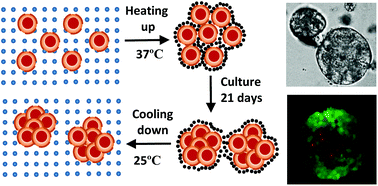
We have previously developed a range of thermo-reversible hydrogels or microgels, and used them to mimic the extracellular microenvironment for mesenchyme stem cells.34–36 In this study we employ these thermo-reversible microgels to culture and harvest tumour spheroids. In our method, as shown in Scheme 1, single cells are homogeneously embedded inside the microgel network that have been heated to 37 °C. Cells proliferate in the cell culture medium, and multiple cells interact to form clusters. After the clusters reach the desired size, the spheroids are easily released and collected by cooling the system down to room temperature. In this confined environment, we expect to obtain uniform-sized spheroids with a narrow size-distribution. We characterize the spheroid size, size distribution and shape, and examine the detailed structure of spheroids through fluorescent images and SEM analysis that is missing from the previous study.37 This approach can be easily adapted for producing large quantities of tumor spheroids for high throughput screening potential drugs.


image file: c6ra11699j-s1.tif
Scheme 1 Thermally sensitive microgels for culturing tumour spheroids: (a) HeLa cells are homogenously mixed with microgels at room temperature; (b) at 37 °C, P(NIPAM-AA) microgels constrain single cells in a three-dimensional network as the microgels are solidified due to the hydrophobic attraction; (c) after incubating HeLa-laden microgels in cell culture medium for a pre-determined period, HeLa multicellular spheroids are generated in P(NIPAM-AA) microgels; (d) by cooling down the temperature to 25 °C, the 3D microgel turns into solution as microgels become hydrophilic again and are re-dispersed into medium, and HeLa spheroids are released from the liquefied solution.

We put forward possible mechanisms for spheroid formation, which we then investigate using an agent-based or cellular automata (CA) model. CA models have previously been widely used to investigate various biological phenomena,38,39 including tumour growth.40–42 However, to our knowledge they have not previously been applied to the study of tumour spheroid formation within hydrogel scaffolds. By changing some of the parameters in our model, we are able to take into account the different environments experienced by cells in hydrogel and suspension cultures, and investigate their effects on spheroid formation. Of particular interest was to determine the factors affecting the uniformity of the spheroid size distribution. Combining the CA model and experimental results, allows us to explore the different mechanisms for tumour spheroid formation in microgel scaffold culture and suspension cultures.

Experimental

Materials

N-Isopropylacrylamide (NIPAM), acrylic acid (AA), N,N′-methylenebis(acrylamide) (MBA), potassium persulphate (KPS) were purchased from Sigma-Aldrich, sodium dodecyl sulphate (SDS) was purchased from VWR. NIPAM was recrystallized in n-hexane and dried in vacuum at room temperature. AA was purified by vacuum distillation. Dulbecco's Modified Eagle's Medium (DMEM), trypsin-EDTA, penicillin–streptomycin (PS) and fetal bovine serum (FBS) were ordered from Gibco. 3-(4,5-Dimethlthiazol-2-yl)-2,5-diphenyltetrazolium bromide (MTT) was purchased from Merck. The LIVE/DEAD® Viability/Cytotoxicity Kit was purchased from Life Technologies.

Microgels synthesis

The P(NIPAM-AA) microgels were synthesized by free radical emulsion polymerization based on the method reported previously34 and the recipe was shown in Table S1. 9.9 mmol NIPAM, 0.1 mmol AA, 0.2 mmol MBA and 0.12 mmol of SDS were dissolved in 97 mL of water. After thoroughly mixing, the solution was transferred to a 250 mL three-necked flask fitted with a condenser and a mechanical stirrer. Before the polymerization, the solution was under nitrogen atmosphere for degassing 30 min. After degassing, the flask was placed into a pre-heated oil batch (70 °C). 3.0 mL of KPS aqueous solution (0.1 mmol) was injected into the mixture solution to initiate the polymerization. The polymerization was carried out for 5 h under the protection of nitrogen atmosphere with continuous stirring. After reducing the temperature to the ambient temperature, the microgels were purified by membrane dialysis with a cut-off molecular weight of 12–14 kDa against Milli-Q water for one week with a daily water change. The purified microgels were concentrated at 70 °C with continuous stirring. The success of copolymerization was confirmed by FTIR (Fig. S1) and titration (Fig. S2) in ESI document.

Tumor spheroid formation from three dimensional cell culture

HeLa cells were cultured in a growth medium (DMEM with 10% FBS and 1% PS) in a T-75 flask. The flask was incubated at 37 °C in a humidified atmosphere with 5% CO2 until it was confluent. Trypsin was added into the flask to harvest cells. Cells were resuspended in a complete growth medium at a cell concentration of 1.4 × 10⁶ cells per mL.

To prevent HeLa cells attached to the bottom of the 24 well plates, all wells were pre-coated with 400 μL 5% agarose. After coating, HeLa cell dispersion was mixed with 50 mg mL−1 microgels (in phosphate buffered saline (PBS), pH ≈ 7.2) at a volumetric ratio of 2[thin space (1/6-em)]:[thin space (1/6-em)]3. Therefore, the initial concentration of cells was 5.6 × 10⁵ cells per mL, and the concentration of microgels was 30 mg mL−1. 0.5 mL of mixture was seeded to each well of a 24-well plate. The cell–microgel mixture was incubated at 37 °C for 2 h until the mixture became soft gel. 1 mL growth medium was added on the top of the soft gel in each well. Cells were incubated at 37 °C in a humidified atmosphere with 5% CO2 and the growth medium was changed daily. Cells were harvested for further analysis at day 7, 14, and 21. For comparison of cell culture in the absence of microgels, 0.5 mL of the HeLa cell dispersion in the complete growth medium with a concentration of 5.6 × 10⁵ cells per mL was seeded to each coated well of a 24-well plate, and then another 1 mL culture medium was added to each well. Other experimental conditions were identical to 3D cell culture in the microgels.

Cell proliferation assay

Cell proliferation was determined by the standard MTT assay. After culturing for a predetermined period, 100 μL MTT solution (5.0 mg mL−1) was added into each well with microgels or without microgels. After further incubating for 4 h, the medium was completely removed. 1 mL DMSO was added to dissolve the formazan crystals. All solutions from each well were transferred to a 96 well plate and the absorbance of the solubilized formazan crystals was recorded using an ELx808 Absorbance Microplate Reader (BioTek Instruments In., USA) at a wavelength of 490 nm.

Spheroid release and collection

After the culture period has elapsed, the scaffold and cells structure are left at room temperature for 1 h. The microgels liquefy when the temperature is below LCST, and the released spheroids can be easily collected through centrifuge.

Spheroid morphology and structure analysis

After the HeLa cells were cultured in the microgels for a fixed time point, the cell-microgel mixture was cooled down to the room temperature. The microgels turned into solution and spheroids were released. The morphology of the HeLa cell spheroids in the microgel solution was observed under an Olympus IX50 inverted microspore (USA). The optical images were analysed by a software package Analysis LSR (USA) to quantify the cell size distribution and sphericity. The spheroids' size was analysed through pictures that were taken from 3 wells (3 pictures per well) for each day and the total number of spheroids analysed was at least 100.

The Live/Dead cell viability/cytotoxicity kit was used to assess live and dead cells in the spheroid structure. The dye solution was prepared according to the protocol from the supplier. 0.3 μL ethidium homodimer-1 (red) and 0.75 μL calcein AM (green) was added 1.5 mL PBS buffer. Before staining, the gel and cells mixture was washed with pre-warmed PBS buffer twice. Then 200 μL dye solution was added to each well. After another 30 minutes incubation at 37 °C, gel and cells mixture was washed with pre-warmed PBS buffer for two more times. A fresh 300 μL PBS buffer was added after rinse process. The stained mixture was observed under confocal microscopy for spheroid morphology examination. The excitation wavelength for calcein AM was selected to be 504–553 nm, and for ethidium homodimer-1 was 569–619 nm. The Leica TCS SP5 confocal microscope was used to record fluorescent images.

The scanning electron microscopy (SEM) was also further employed for spheroid structure analysis. The cellular spheroid was fixed for 30 min in the EM fixative (4% paraformaldehyde/1.25% glutaraldehyde in PBS, and 4% sucrose, pH 7.2). The sample was rinsed in a washing buffer (PBS + 4% sucrose) for 5 min. The spheroid was post-fixed in a 2% OsO4 aqueous solution for 30 min. After fixing the sample, the sample was dehydrated by rinsing it by 70%, 90% and 100% ethanol thrice and 10 min for each step. The sample was submerged into a mixture of HMDS (hexamethyldisilazane) and 100% ethanol at a volumetric ratio of 1[thin space (1/6-em)]:[thin space (1/6-em)]1 for 10 min. The sample was further placed into 100% HMDS for 10 min. HMDS was removed and the sample was dried. The dried sample was coated with platinum and observed under a Philips XL30 Field Emission Scanning Electron Microscope at an accelerating voltage of 10 kV.

Development of CA model

The CA model consists of a lattice, where each site on the lattice can either be empty or occupied by a cell. At the beginning of a simulation, a specified number of cells are placed at random on the lattice. The number and position of the cells are updated at discrete time intervals. During each timestep, cells are selected in random order, and act according to rules for cell behaviour (including cell movement, proliferation and death) that are described in detail below. Our model uses a two-dimensional lattice, as the experimental data derives from two-dimensional images. This has the further advantage of reducing the computational cost compared to a three-dimensional model. The method by which we take into account the three-dimensional nature of the experiments is explained in detail below.
Cell movement. We let the probability that a cell will attempt to move during a time step be Pm. We assume this probability will depend upon the cell's environment. We take a higher value of Pm to represent cells in suspension, and a lower value of Pm for cells in microgels, representing some resistance to movement (such as cell–ECM adhesion, and high viscosity of microgel solution). Cell movement is assumed to involve two component behaviours: unbiased random motion (in which a cell will attempt to move to one of the four neighbouring lattice sites with equal probability) and biased motion (where cells will preferentially move towards other cells). In our model, cells attempt to move according to the biased motion rule with probability Pb (hence the probability of moving according to the unbiased random motion rule is 1 − Pb). Thus the tendency of cells to aggregation is represented by the probability of biased motion, Pb: for cell types that are strongly inclined to create clusters after seeding, Pb will be close to one, whilst for those that do not tend to aggregate, Pb is close to zero.43 Pb and Pm are chosen based on the hypothesised characteristics of the cells in the medium before the start of each simulation.

When a cell attempts to move using the biased motion rule, the direction in which it moves is determined as follows. For each of the four directions, we calculate the following probability:

 
image file: c6ra11699j-t1.tif (1)
where v(k) is the number of cells at the right (k = 1), left (k = 2), up (k = 3) and down (k = 4) direction of a cell within its range of attraction (l) (see Fig. 1). Note that the Pv(k) sum to unity. We then subdivide the interval [0,1] into four sub-intervals: [0, Pv(1)], (Pv(1), Pv(1) + Pv(2)], (Pv(1) + Pv(2), 1 − Pv(4)), (1 − Pv(4), 1], and draw a random number uniformly distributed on [0,1]. If the number chosen lies in the first interval, the cell attempts to move right, if in the second, it attempts to move left, etc.


image file: c6ra11699j-f1.tif
Fig. 1 A sample distribution of cells is depicted. For example, the red cell marked out with the black border senses 7 cells at its right side, v(k = 1) = 7, where l = 3 is the radius of the attraction range, illustrated by the shaded sites.

Area exclusion is accounted for in the cell movement rules:44 two or more cells cannot occupy a site at a time. Therefore, if at any point a cell attempts to move to an already occupied site, the movement is aborted.

Mombach and Glazier45 suggest that in unbiased motion a cell moves 1/6 of its diameter in 30 minutes. Therefore, in 3 hours each cell moves one site in the lattice when Pm = 1.

The probability of biased motion is set to Pb = 0.9 with the range of attraction, l = 3 for both types of culture. Thus, it is very likely that the cells move towards each other when they are very close to each other (e.g. close enough that some parts of the cell may make physical contact). Long range attractions are not considered here as chemotactic signals are assumed to be negligible.

Cell proliferation. The probability of proliferation, Pp, determines the rate of proliferation at each timestep. When proliferation occurs for a cell, the parent cell keeps its position and the daughter cell occupies one of the four adjacent sites. Area exclusion is accounted for in the proliferation rules as well, i.e. if a cell already occupies the chosen site for the daughter, the proliferation event is aborted.

We follow the model of Qi et al.40 who take into account the effects of nutrient depletion as cancer cells proliferate by making the probability of proliferation dependent upon the total number of cells. We define the two-dimensional cell density, ρ, as the area fraction occupied by the cells, given by

image file: c6ra11699j-t2.tif
where N(t) is the number of cells at time t, B is the cell area (152 μm2) and A is the area of the lattice in μm2. The area of a well in the experiments is around 20 mm2. Thus, the length of each side of the well is image file: c6ra11699j-t3.tif Therefore, a lattice representing the wells has a length of L = a/0.015 = 300 sites. As the proliferation rate is assumed to decrease when cell density increases, due to lack of nutrients, we define the probability of proliferation as
image file: c6ra11699j-t4.tif
where C is carrying capacity and k is growth rate. Qi et al.40 suggest 0.26 d−1 < k < 0.48 d−1. From the experimental data shown in Fig. 2, cells have approximately the same rate of proliferation in suspension and microgel: we hence use the same probability of proliferation for both types of culture with k = 0.48 d−1 = 0.06 (3 h)−1. C is estimated to be 0.6 by processing the images of the experiments to obtain the maximum area fraction that may occur.


image file: c6ra11699j-f2.tif
Fig. 2 The probability of death (Pd) applied in the CA model, described in eqn (1.1). Δt is the number of timesteps (each of 3 h) where a cell is not adhered to another cell.
Cell death. Cells need to adhere to another cell or a surface to survive and proliferate.46 As the cells in suspension culture are prevented from adhering to the substrate, we assume that they are likely to die after one day if they do not adhere to other cells.47,48 In the model, we assume a cell is adhered to another cell if there is a least one cell in the four squares adjacent to it. However, in microgel culture, the cells can survive and proliferate by adhering to the microgel. We thus considered two different death probabilities, Pd, in simulations of suspension and microgel experiments. In suspension simulations, Pd for an isolated cell is low during the first day of culture, increasing rapidly to unity thereafter. For microgel simulations, for the sake of simplicity, Pd is taken to be zero.

Thus, the probability of death for isolated cells in suspension and microgel culture respectively can be defined as follows

 
image file: c6ra11699j-t5.tif(1.1)
where Δt is the number of timesteps (each timestep represents 3 h) where a cell is not adhered to another cell. This equation gives a rapid increase in the death probability after Δt = 8 (1 day) for suspension culture, whilst Pd = 0 for microgel cultures for 0 ≤ Δt ≤ 168 timesteps, see Fig. 2. Note that the functional form of Pd in eqn (1.1) is simply chosen to reproduce the assumed qualitative behaviour of the cells in the two different culture environments described above. In the case of suspension culture, other functions that increase rapidly to unity after a period of 1 day would be expected to produce similar results.

The CA model was run with a timestep, Ts, of 3 hours. The initial population was set to ρ0 = ρ(0) = 0.05 in suspension and ρ0 = 0.005 in microgel to have the best fit to the experiments. The reason for this difference is that in suspension most cells settle down and interact in a layer close to the substrate, whereas the cells in microgels lie in multiple layers. Note that ρ0 represents the effective initial population of cells in our 2D CA model, i.e. the cells that interact with each other within a layer, not the total population of cells in a well. This leads to a considerably higher effective ρ0 for the suspension culture case where the cells are mainly within one layer, compared to the microgel, where they are distributed more evenly throughout the gel.

The length of the lattice side was scaled down to half: 150 sites, similar to the size of the images of the experiments. Moreover, a periodic boundary condition was applied in the simulations. This means that when a cell moves out of the domain at one side, it will re-enter from the opposite side. Applying periodic boundary conditions mitigates the effect of boundaries on the distribution of cells,43 since there is no physical boundary present at the edge of the experimental images with which we aim to compare our results.

The size of the clusters (cluster diameter) was calculated as follows. Firstly, the areas of the clusters were computed, using the function #bwarea in MATLAB. This function gives an estimate of the area, n, created from adjacent connected pixels, using the algorithm explained in ref. 49. Multiplying the area by 152 (area of a cell), gave the area of a cluster in μm2. The cluster diameter, D, was then calculated as the diameter of a circular cluster of equivalent area – i.e.:

image file: c6ra11699j-t6.tif

Data analysis

All experimental data were expressed with mean ± standard deviation. Student's t test was used to for statistical analysis. Data were considered to be significantly different at p < 0.05.

Results and discussion

Cell proliferation

We have previously used synthesized microgels to culture mesenchymal stem cells and promote cell proliferation in the three dimensional network.34–36 We again employed this novel three-dimensional cell culture platform in this study to form HeLa tumor spheroids and compare them with suspension culture controls. When HeLa cells are cultured in the microgels, the cells display rapid proliferation in the first 7 days, maintain a dynamically balanced cell growth from day 7 to 14, and start to decrease in cell number from day 14 to 21 as shown in Fig. 3. A similar trend of cell proliferation was also observed for the cells in suspension culture. Interestingly, the growth kinetics for HeLa cells in microgels are quite similar to those of tumour in vivo.50
image file: c6ra11699j-f3.tif
Fig. 3 HeLa cell proliferation inside the microgel network. The experiment was performed in parallel (mean ± SD, n = 12). ‘*’ indicates p < 0.05.

At day 1 the MTT result shows cells growing within microgels or in suspension have a very similar absorbance rates which indicates good biocompatibility of the P(NIPAM-AA) microgels with HeLa cells. At day 7, cells in suspension proliferate relatively faster than those within the microgels. However, the number of viable cells increases significantly in microgels, which means oxygen and nutrients can diffuse through the microgel pore networks to support cell growth. As cell growth progresses, the number of proliferating cells starts to decrease and the proportion of non-proliferating (quiescent) cells starts to increase.50 This may be due to the maximum cell density being achieved in each well.37 However, the lower growth rate in the microgels in the previous 7 days results in more rapid growth from day 7 to day 14 in comparison with suspension culture. At day 21, the viable cell number with and without gels shows a dramatic drop. This may be due to formation of large clusters in which the inner cells are dead because of limited oxygen and nutrients. At this stage, the maximum size of clusters is reached, and there are many more inner dead cells. Cell death may also due to toxic products discharged by the cells.37

Spheroid structure analysis

The Live/Dead viability and cytotoxicity kit was further employed to examine the structure of individual tumour spheroids. Live cells are coloured green, whilst dead cells are red. The fluorescent images clearly show the inner structure of the spheroids. Fig. 4a–d illustrates the progression of spheroid development. At day 1, the single cells are dispersed in the microgel network. At day 7, as shown in Fig. 4b, small clusters are able to be seen and the inner cells become dead due to starvation of oxygen, glucose and other nutrients as well as accumulation of toxic metabolites secreted by cells.50 A solid and compact spheroid structure appears at day 14, and dead cells in the central core are distinguishable from those in the outer layers. At day 21, the compact structure becomes loose and some cells detach from it and start to migrate away. High-resolution SEM images in Fig. 4 clearly reveal the spheroid structure. Cells are tightly bound to each other to form a nearly spherical structure (Fig. 4e). The strong interaction between cells results in the compact spheroid structure (Fig. 4f and S3). This confirms that the cell adhesion is one of the key driving forces to maintain the structure.
image file: c6ra11699j-f4.tif
Fig. 4 HeLa cell Live/Dead and SEM images. (a–e) HeLa cells fluorescent images within microgel network at day 1, day 7, day 14, day 21 respectively. Scale bar is 100 μm. (e and f) SEM of a HeLa cell spheroid at day 7 at different scale, 20 μm for (e) and 5 μm for (f).

Spheroid size analysis

The physiological state of spheroids is dependent on their size and the cell density within them. Three dimensional cell–cell and cell–matrix interactions are established when the spheroid size reaches 150 μm and gene expression profiles are significantly altered, compared to 2D culture. Chemical gradients, such as oxygen, nutrients and catabolizes, are developed at diameters between 200 μm and 500 μm, and a central secondary necrosis is established for a diameter greater than 500 μm. Thus, spheroid size has a great impact on drug screening. Optical images were used to study the morphology of the spheroids, and the images are presented in Fig. 5. 4× magnification images reveal the evolution of cluster sizes at each time stage. It can be seen that cells remaining inside of microgels tend to form a cluster structure at a slower rate than those in suspension. At day 7, without the control of microgels, cells cultured in the suspension medium have formed a cluster structure (Fig. 5a), while cells grown in the microgels form a much smaller cluster containing two or three cells (Fig. 5b). At day 14, a clear spheroid structure can be observed both within and without microgels. However, the size of the clusters in microgels (Fig. 5c) is considerably less than those in suspension medium (Fig. 5d). A number of single cells are seen in the microgel system. After culturing for 21 days, the number of clusters within microgels increases although some single cells can still be observed (Fig. 5e). In suspension culture, the number of clusters begins to drop but the size of the clusters continues to increase (Fig. 5f).
image file: c6ra11699j-f5.tif
Fig. 5 HeLa cells in microgel (a, c and e) and suspension culture (b, d and f) at different culture days at room temperature. Scale bar is 500 μm. (a), (c) and (e) show HeLa cells within microgel culture after 7 days, 14 days and 21 days respectively. (b), (d) and (f) show HeLa cells in suspension culture after 7 days, 14 days and 21 days respectively.

Clusters may be formed due to interactions between two neighbouring cells or between parent and the daughter cells, depending on their physical locations and the secretory molecules surrounding them.31 Clusters in the suspension medium may be formed due to interactions between parent and daughter cells as well as neighbouring cells. Further increases in cluster size may be due to cluster–cluster, cluster–cell and cell–cell interactions. However, inside the microgels, the restraint provided by the microgel networks slows down the formation of cell clusters. Neighbouring cells inside the scaffold are separated by the physical barriers formed by the microgel network and they cannot migrate freely to form clusters. Most likely, clusters are formed by parent cells and their adjacent daughters. On the first day, the cell density is low, and cells are scattered inside the microgel network. Gradually cells start to proliferate and two-cell clusters are formed. As the culture time increases, multicellular spheroid structures are generated.

Cluster size distribution

The optical images were further analysed using an imaging software package to obtain the size distribution of the clusters which is shown in Fig. 6. At the first 7 days, cells grown in microgels form clusters with a size range of 20 μm to 70 μm (Fig. 6a). By contrast, cells grown in suspension form larger clusters more rapidly. More than 60% of the clusters are bigger than 70 μm. Most clusters are around 70 μm to 120 μm (Fig. 6b). At day 14, a shift in spheroid size towards larger sizes becomes more evident in both types of culture. The majority of clusters in microgels are around 70 μm to 120 μm with a narrow size distribution, while the cluster size in the suspension medium shows a much wider distribution. Equal numbers of spheroids are found in the range of 70 μm to 120 μm and 120 μm to 170 μm. Bigger-sized clusters can be observed in the suspension medium than in microgels. At day 21, the cluster size increases again. The incremental rate of cluster size growth in the suspension medium is much faster than that in the microgels. In microgel scaffold culture, the majority of the cluster sizes are in the range 70 μm to 120 μm, with a relatively narrower size distribution than that for suspension culture.
image file: c6ra11699j-f6.tif
Fig. 6 HeLa cell spheroid size distribution. (a), (c) and (e) show results for HeLa cells within microgel culture after 7 days, 14 days, and 21 days respectively. (b), (d) and (f) show results for HeLa cells in suspension culture after 7 days, 14 days and 21 days respectively.

The stiff microenvironment formed by the microgels has a significant impact on the size distribution of spheroids. It has been reported that a higher stiffness surrounding cells results in much smaller spheroids.51 The microgels generated in the study are relatively soft, with an elastic modulus (G′) of around 1 Pa, far less than the values reported ranging from 241 to 1201 Pa G′ of other hydrogels.51 It would be expected that a higher stiffness may also lead to a very narrow size distribution. However, spheroids with a size below 150 μm generated in the in vitro environment may not be able to represent the tumours in the human body. It is clearly shown that the soft microgels in our study can significantly reduce variability in spheroid size and also produce spheroids with a size range similar to the in vivo environment.

Sphericity

The measurement of sphericity was based on the central moment, and the sphericity is defined as the ratio of the perimeter of the circle with the same projected area as the cluster (πdeq) to the perimeter of the cluster (P):52
s = πdeq/P

The calculated sphericities for spheroids with and without microgels are shown in Fig. 7. It can be seen from Fig. 7 that the sphericity in the suspension does not vary with the culture time. Above 70% of clusters have sphericity of 0.4 to 0.6, which means the shape of the clusters is far from spherical. In the microgel culture, at day 7, the sphericity seems similar to that in the suspension medium. However, over 70% of clusters present sphericity of 0.8–1.0, showing that the most of clusters exhibit a spherical shape. As the culture time extends to 21 days, the sphericity shifts from 0.8–1.0 to 0.6–0.8, with the frequency of eccentric shapes increasing after 14 days in culture. The results demonstrate the stiffness of the microenvironment formed by microgels also plays a role in maintaining the spherical shape of spheroids.


image file: c6ra11699j-f7.tif
Fig. 7 Sphericity of HeLa clusters in microgel and suspension culture. (a), (c) and (e) show results for HeLa cells within microgel culture after 7 days, 14 days, and 21 days respectively. (b), (d) and (f) show results for HeLa cells in suspension culture after 7 days, 14 days and 21 days respectively.

CA model

Fig. 8 shows the pattern and distribution of clusters in suspension and microgel simulations. Here, we consider extreme cases where Pm is 1 for suspension and 0 for microgels respectively. Thus, the cells are very motile in suspension and the cells in microgels do not move at all. Note that in the histograms clusters with n < 7 are not included, since they are too small to be considered as spheroids.
image file: c6ra11699j-f8.tif
Fig. 8 Visualisations of spheroid formation and the distribution of cluster sizes in microgel (left box) and suspension (right box) simulations. (a and d) day 7, (b and e) day 14 and (c and f) day 21. The average with the 95% confidence intervals of the t-distribution are depicted for 50 simulations. In suspension: Pm = 1 and ρ0 = 0.05. In microgel: Pm = 0 and ρ0 = 0.005. The lattice has side of L = 150 sites, the range of attraction is l = 3, the probability of biased movement is Pb = 0.9, the proliferation constant is k = 0.06, the carrying capacity is C = 0.6 and the death probability is defined in eqn (1.1). The dead cells are not shown in the images. Time lapses of the evolving distribution of cells for suspension and microgel cultures are shown in the ESI document.

Comparing Fig. 8 with 5 shows that the simulation results are in good agreement with the experimental results. At day 21, the average cluster size is [D with combining macron] ≈ 186 μm and the standard deviation of the cluster size is δ ≈ 107 μm for simulated suspension cultures, while [D with combining macron] ≈ 133 μm and δ ≈ 54 μm for simulated microgel cultures. Hence, the distribution of clusters is more uniform in the microgel with a lower standard deviation and the average cluster size is smaller as well.

The main differences between the simulated suspension and microgel experiments are in the motion of cells and the initial cell density. We aim to understand how each of them affects the distribution of cluster size, and so, parameter-sweeping tests were carried out in which one of the parameters is varied while the others are kept constant. We swept the parameters in a physically plausible region, i.e. where their values are within a range that is consistent with the physical properties of the medium. Small variations about the previous values of Pm and ρ0 (see the caption of Fig. 9) are analysed.


image file: c6ra11699j-f9.tif
Fig. 9 Parameter sweeping tests. Standard deviation, δ, and average, [D with combining macron], of cluster size are depicted. (a and b) Microgel: ρ0 = {0.005, 0.01, 0.015, 0.02}. Pm = 0 black, Pm = 0.005 blue and Pm = 0.01 red. (c and d) Suspension: ρ0 = {0.035, 0.04, 0.045, 0.05}. Pm = 0.8 black, Pm = 0.9 blue, Pm = 1 red. The points in the graphs are averages over 50 simulations and the error bars are 95% confidence intervals of the t-distribution. The values of the other parameters are the same as in Fig. 8.

We have also examined general cases where the parameter ranges are not necessarily in the plausible region, see ESI Fig. S4 and S5. This allows us to analyse other different media that might be used for spheroid formation in future work.

The parameter sweeping was done for 150 × 150 lattice with ρ0 = {0.005, 0.01, 0.015, 0.02} and Pm = {0, 0.005, 0.01} in the microgel and ρ0 = {0.035, 0.04, 0.045, 0.05} and Pm = {0.8, 0.9, 1} in suspension. Fig. 9 shows that [D with combining macron] and δ increase with ρ0. Thus our model suggests that using a higher initial cell density, ρ0, leads to formation of bigger clusters, which is desirable, but this has the unwanted effect of reducing the uniformity of cluster size. Hence the choice of ρ0 would involve a trade-off between cluster size and size-variability.

As illustrated in Fig. 9b and d, our model predicts that the rate of increase of δ with ρ0 for microgel culture is greater than for suspension culture. Thus, increasing the initial population would have a more deleterious effect on the uniformity of the clusters in microgels compared to suspension culture.

Sweeping the values of Pm in a wider range, we determined that motility of cells can strongly affect [D with combining macron] and δ. Fig. S4 in ESI shows that increasing Pm leads to the formation of bigger clusters. The reason is that, when Pm is high enough, randomly moving cells can find bigger clusters nearby and attach to them. In addition, the highly motile cells in small clusters are more likely to find bigger clusters and attach to them. Therefore, increasing Pm can reduce the number of small clusters and increase the number of larger ones. Further details can be found in the ESI.

Conclusion

In summary, we conducted a series of experiments to demonstrate the advantages of using microgel scaffolds to culture tumour spheroids instead of conventional suspension culture methods. Microgel culture produces more uniformly-sized spheroids, with a more spherical shape. Also it could be used for scalable production of multicellular spheroids. The introduction of the microgel network can be helpful to mimic the stiff environment of tumour growth in vivo. Spheroids produced by our technique can be easily released and collected. Further study on the details of cells' behaviour in microgels can be conducted, and the mechanism of spheroid formation will help understanding of the spheroid formation progress in real tissue. This material, with some modifications, could be used to re-create a controlled microenvironment for other scaffold applications such as regenerative medicine, tissue engineering and so forth.

We developed a CA model to explore the reasons for the different size distributions observed in spheroids grown in microgels and suspension culture. In the model, the cells behave according to rules for movement, proliferation and death. We tried to keep the model as simple as possible in order to focus on the effect of the major parameters on spheroid formation. The CA model was developed in two-dimensions, since this facilitates comparison with the two-dimensional experimental images, and also reduces the computation time required.

Our CA model was successfully able to reproduce the experimental results for spheroid formation rate and size distribution, for both microgel and suspension cultures. Our results are thus consistent with the main differences between cells in the two different cultures being in their proliferation and death rates, and their initial effective density. Hence, the more uniform size distribution of spheroids produced by microgel culture could be due to its ability to separate the cells into multiple layers, reducing the effective initial density. However, even when the number of cells is low, the microgel provides a substrate for cells to survive and proliferate, so spheroids can still be produced. By contrast it is not possible to reduce the initial population of cells significantly in suspension cultures, since the cells would die out and spheroid formation would not occur.

The model predicts that the initial cell density plays a crucial role in determining the features of the formed spheroids. For the parameter ranges we considered, higher initial densities led to larger spheroids, but at the cost of introducing greater variability in spheroid size. This effect was predicted to be more pronounced for microgel cultures than suspension cultures. Further experiments will be required to test these predictions.

Acknowledgements

X. C. acknowledges financial support from a University of Adelaide scholarship. H. Z. would like to acknowledge the financial support from ARC Discovery Project (DP160104632) and The Medical Advancement Without Animal (MAWA) Trust. The work of S. D. and J. E. F. G. was supported by an ARC Discovery Early Career Researcher Award (DE130100031) to J. E. F. G. S. D. also acknowledges a University of Adelaide Full Fees Scholarship. B. J. B. was supported by an ARC Discovery Project Grant (DP160102644). H. Z. and J. E. F. G. thank the Faculty of Engineering, Computer & Mathematical Sciences of the University of Adelaide for multidisciplinary research collaboration funding.

References

  1. A. Nyga, U. Cheema and M. Loizidou, Journal of Cell Communication and Signaling, 2011, 5, 239–248 CrossRef PubMed.
  2. C. Wang, Z. Tang, Y. Zhao, R. Yao, L. Li and W. Sun, Biofabrication, 2014, 6, 022001 CrossRef PubMed.
  3. F. Hirschhaeuser, H. Menne, C. Dittfeld, J. West, W. Mueller-Klieser and L. A. Kunz-Schughart, J. Biotechnol., 2010, 148, 3–15 CrossRef CAS PubMed.
  4. J. Landry, D. Bernier, C. Ouellet, R. a. Goyette and N. Marceau, J. Cell Biol., 1985, 101, 914–923 CrossRef CAS PubMed.
  5. J. M. Yuhas, A. P. Li, A. O. Martinez and A. J. Ladman, Cancer Res., 1977, 37, 3639–3643 CAS.
  6. G. A. Hamilton, C. Westmoreland and E. George, In Vitro Cell. Dev. Biol.: Anim., 2001, 37, 656–667 CrossRef CAS.
  7. S. L. Nyberg, J. Hardin, B. Amiot, U. A. Argikar, R. P. Remmel and P. Rinaldo, Liver Transplant., 2005, 11, 901–910 CrossRef PubMed.
  8. A. Lazar, H. J. Mann, R. P. Remmel, R. A. Shatford, F. B. Cerra and W.-S. Hu, In Vitro Cell. Dev. Biol.: Anim., 1995, 31, 340–346 CrossRef CAS PubMed.
  9. H. Song, O. David, S. Clejan, C. L. Giordano, H. Pappas-Lebeau, L. Xu and K. C. O'connor, Tissue Eng., 2004, 10, 1266–1276 CrossRef CAS PubMed.
  10. R.-Z. Lin, L.-F. Chou, C.-C. M. Chien and H.-Y. Chang, Cell Tissue Res., 2006, 324, 411–422 CrossRef CAS PubMed.
  11. J. M. Kelm, N. E. Timmins, C. J. Brown, M. Fussenegger and L. K. Nielsen, Biotechnol. Bioeng., 2003, 83, 173–180 CrossRef CAS PubMed.
  12. J. M. Kelm and M. Fussenegger, Trends Biotechnol., 2004, 22, 195–202 CrossRef CAS PubMed.
  13. M. Wartenberg, F. Dönmez, F. C. Ling, H. Acker, J. Hescheler and H. Sauer, FASEB J., 2001, 15, 995–1005 CrossRef CAS PubMed.
  14. J. M. Kelm, V. Djonov, L. M. Ittner, D. Fluri, W. Born, S. P. Hoerstrup and M. Fussenegger, Tissue Eng., 2006, 12, 2151–2160 CrossRef PubMed.
  15. M. Ingram, G. Techy, R. Saroufeem, O. Yazan, K. Narayan, T. Goodwin and G. Spaulding, In Vitro Cell. Dev. Biol.: Anim., 1997, 33, 459–466 CrossRef CAS PubMed.
  16. V. I. Khaoustov, G. J. Darlington, H. E. Soriano, B. Krishnan, D. Risin, N. R. Pellis and B. Yoffe, In Vitro Cell. Dev. Biol.: Anim., 1999, 35, 501–509 CrossRef CAS PubMed.
  17. H. K. Kleinman and G. R. Martin, Semin. Cancer Biol., 2005, 15, 378–386 CrossRef CAS PubMed.
  18. R. H. Kramer, K. G. Bensch and J. Wong, Cancer Res., 1986, 46, 1980–1989 CAS.
  19. R. Castelló-Cros, D. R. Khan, J. Simons, M. Valianou and E. Cukierman, BMC Cancer, 2009, 9, 94 CrossRef PubMed.
  20. D. L. Holliday, K. T. Brouilette, A. Markert, L. A. Gordon and J. L. Jones, Breast Cancer Res., 2009, 11, R3 CrossRef PubMed.
  21. L. A. Gurski, A. K. Jha, C. Zhang, X. Jia and M. C. Farach-Carson, Biomaterials, 2009, 30, 6076–6085 CrossRef CAS PubMed.
  22. S. Talukdar, M. Mandal, D. W. Hutmacher, P. J. Russell, C. Soekmadji and S. C. Kundu, Biomaterials, 2011, 32, 2149–2159 CrossRef CAS PubMed.
  23. M. J. Paszek, N. Zahir, K. R. Johnson, J. N. Lakins, G. I. Rozenberg, A. Gefen, C. A. Reinhart-King, S. S. Margulies, M. Dembo and D. Boettiger, Cancer cell, 2005, 8, 241–254 CrossRef CAS PubMed.
  24. B. Weigelt and M. J. Bissell, Semin. Cancer Biol., 2008, 18, 311–321 CrossRef CAS PubMed.
  25. R. Langer and D. A. Tirrell, Nature, 2004, 428, 487–492 CrossRef CAS PubMed.
  26. M. Lutolf and J. Hubbell, Nat. Biotechnol., 2005, 23, 47–55 CrossRef CAS PubMed.
  27. L. G. Griffith and M. A. Swartz, Nat. Rev. Mol. Cell Biol., 2006, 7, 211–224 CrossRef CAS PubMed.
  28. M. P. Lutolf, Integr. Biol., 2009, 1, 235–241 RSC.
  29. D. Loessner, K. S. Stok, M. P. Lutolf, D. W. Hutmacher, J. A. Clements and S. C. Rizzi, Biomaterials, 2010, 31, 8494–8506 CrossRef CAS PubMed.
  30. Y. Lei and D. V. Schaffer, Proc. Natl. Acad. Sci. U. S. A., 2013, 110, E5039–E5048 CrossRef CAS PubMed.
  31. Y. Wu, Z. Zhao, Y. Guan and Y. Zhang, Acta Biomater., 2014, 10, 1965–1974 CrossRef CAS PubMed.
  32. M. Ehrbar, S. C. Rizzi, R. Hlushchuk, V. Djonov, A. H. Zisch, J. A. Hubbell, F. E. Weber and M. P. Lutolf, Biomaterials, 2007, 28, 3856–3866 CrossRef CAS PubMed.
  33. M. Ehrbar, S. C. Rizzi, R. G. Schoenmakers, B. San Miguel, J. A. Hubbell, F. E. Weber and M. P. Lutolf, Biomacromolecules, 2007, 8, 3000–3007 CrossRef CAS PubMed.
  34. Z. Shen, J. Bi, B. Shi, D. Nguyen, C. J. Xian, H. Zhang and S. Dai, Soft Matter, 2012, 8, 7250–7257 RSC.
  35. Z. Shen, A. Mellati, J. Bi, H. Zhang and S. Dai, RSC Adv., 2014, 4, 29146–29156 RSC.
  36. A. Mellati, S. Dai, J. Bi, B. Jin and H. Zhang, RSC Adv., 2014, 4, 63951–63961 RSC.
  37. D. Wang, D. Cheng, Y. Guan and Y. Zhang, Biomacromolecules, 2011, 12, 578–584 CrossRef CAS PubMed.
  38. G. B. Ermentrout and L. Edelstein-Keshet, J. Theor. Biol., 1993, 160, 97–133 CrossRef CAS PubMed.
  39. T. Toffoli and N. Margolus, Cellular automata machines: a new environment for modeling, MIT press, 1987 Search PubMed.
  40. A.-S. Qi, X. Zheng, C.-Y. Du and B.-S. An, J. Theor. Biol., 1993, 161, 1–12 CrossRef CAS PubMed.
  41. A. A. Patel, E. T. Gawlinski, S. K. Lemieux and R. A. Gatenby, J. Theor. Biol., 2001, 213, 315–331 CrossRef CAS PubMed.
  42. Y. Jiao and S. Torquato, PLoS Comput. Biol., 2011, 7, e1002314 CAS.
  43. D. Agnew, J. Green, T. Brown, M. Simpson and B. Binder, J. Theor. Biol., 2014, 352, 16–23 CrossRef CAS PubMed.
  44. B. J. Binder and K. A. Landman, J. Theor. Biol., 2009, 259, 541–551 CrossRef PubMed.
  45. J. C. Mombach and J. A. Glazier, Phys. Rev. Lett., 1996, 76, 3032 CrossRef CAS PubMed.
  46. B. Alberts, A. Johnson, J. Lewis, M. Raff, K. Roberts and P. Walter, Molecular Biology of the Cell, 4th edn, 2002 Search PubMed.
  47. A. Gilmore, Cell Death Differ., 2005, 12, 1473–1477 CrossRef CAS PubMed.
  48. Q. Wei, V. Hariharan and H. Huang, PLoS One, 2011, 6, e27064 CAS.
  49. W. K. Pratt, Digital Image Processing: PIKS Inside, 3rd edn, 1991, pp. 551–587 Search PubMed.
  50. R. M. Sutherland, Science, 1988, 240, 177–184 CAS.
  51. D. Loessner, J. A. Flegg, H. M. Byrne, J. Clements and D. Hutmacher, Integr. Biol., 2013, 5, 597–605 RSC.
  52. A. Asundi, Digital holography for MEMS and microsystem metrology, John Wiley & Sons, 2011 Search PubMed.

Footnote

Electronic supplementary information (ESI) available. See DOI: 10.1039/c6ra11699j

This journal is © The Royal Society of Chemistry 2016
Click here to see how this site uses Cookies. View our privacy policy here.