Mohammad Ali Zolfigol* and
Roya Ayazi-Nasrabadi*
Faculty of Chemistry, Bu-Ali Sina University, Hamedan 6517838683, Iran. E-mail: zolfi@basu.ac.ir; mzolfigol@yahoo.com; r.ayazi.86@gmail.com; Fax: +98 8138257407
First published on 8th July 2016
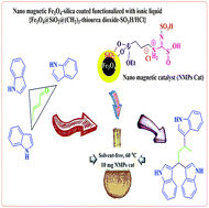
Novel and recyclable thiourea dioxide-based magnetic nanoparticles with a sulfonic acid tag {Fe3O4@SiO2@(CH2)3–thiourea dioxide–SO3H/HCl} are described. The described catalyst was fully characterized using Fourier transform infrared spectroscopy (FTIR), X-ray diffraction (XRD) patterns, scanning electron microscopy (SEM), energy-dispersive X-ray spectroscopy (EDX), transmission electron microscopy (TEM), thermogravimetric analysis (TGA), atomic force microscopy (AFM) and ultraviolet-visible spectroscopy (UV/Vis). The reported novel magnetic nanocatalyst presents an excellent activity and catalytic performance for the synthesis of 1,1,3-tri(1H-indol-3-yl)alkane derivatives through one-pot three-component mixed Mannich-type and Friedel–Crafts reactions under solvent-free conditions at 60 °C.
One of the important and significant groups of nanoparticles is magnetic nanoparticles (MNPs) because as a supported catalyst they have very particular properties such as high surface areas and ease of separation of the catalyst on reaction completion due to them having magnetic properties.6–8 The ideal characteristics include chemically stability, low toxicity, being affordable and, most importantly, a quick, facile and convenient separation using an external magnet without any filtration, which makes them a serious and considerable substitute over other heterogeneous catalytic systems. Magnetic nanoparticles can be functionalized with a wide range of diverse groups such as organic compounds, metals and polymers, and so can be used as a catalyst with diverse and various applications.7d,9–11
There tends to be aggregation between pure Fe3O4 magnetic nanoparticles due to the intense dipole–dipole attraction. Therefore, the magnetic nanoparticles become stuck together, forming large clusters, and they have limited functional groups and lose the specific properties.12 One of the common methods used to modify and improve the performance surface, is coating of the magnetic nanoparticles (MNPs) with a layer of silica.13 Manipulating their surface could improve the chemical stability of the magnetite nanoparticles via preventing the magnetic nanoparticles from aggregating. Silica coating creates an inert surface, so can be used in biological systems. Moreover, silica-coated nanoparticles can be easily functionalized with silanol groups, which can conjugate with a range of different chemical entities. Subsequently enabling their use in a large number of applications.14
MNPs functionalized with sulfonic acid is a significant branch of magnetic nanoparticle research. Various solid acid catalysts with a variety of acid sites have been considered in many different processes. Frequently solid acids are mild, non-toxic, very selective and reusable, therefore they can be regarded as environmentally friendly.15,16 Lately, a group of catalysts known as ionic liquids has been developed for the synthesis of compounds and they have unique attributes. An important and useful category of ionic liquids (ILs) is Brønsted acid ionic liquids functionalized with sulfonic acid that can act as a good acidic catalyst to advance different reactions.17
Thiourea dioxide (TUD) has been prepared via the oxidation reaction of thiourea with hydrogen peroxide. TUD has several important advantages, both in industry and in academia.18 It can have a variety of applications including as a reagent with multiple roles,19 a catalyst20 and a reductant.21
To the best of our knowledge, heterocyclic ring systems, which are widespread in natural compounds, have a key role in life.22 The Michael addition reaction that is named as a conjugate addition is a versatile synthetic method that is also used as another efficient method for the formation of new C–C bonds.23 The Friedel–Crafts reaction is a typical electrophilic substitution reaction for carbon–carbon bond forming processes.24 A Michael/Friedel–Crafts cascade of indolyl moieties, as the electron-rich component, with electron-deficient enals or enones is the most efficient strategy that can give a wide range of important biologically active molecules, which have further applications in molecular medicine.25,26
As a part of our continued interest in the design, synthesis, application and knowledge-based development of solid acids,27 nanocatalysts,28 magnetic nanocatalysts,29 task-specific ionic liquids (TSILs)30 and inorganic acidic salts,31 and due to the specific characteristics of magnetic nanoparticles, solid acids and ionic liquids, herein, we decided to join all of the above-mentioned research projects to provide a novel catalyst. Thus, to achieve this goal, we have designed, prepared and used thiourea dioxide-based ionic liquid stabilized on silica-coated Fe3O4 magnetic nanoparticles {Fe3O4@SiO2@(CH2)3–thiourea dioxide–SO3H/HCl} for the synthesis of 1,1,3-tri(1H-indol-3-yl) alkane derivatives under solvent-free conditions (Scheme 1).
The infrared spectra (FT-IR) of the bare Fe3O4 magnetic nanoparticles, the Fe3O4@SiO2 core–shell MNPs and the other core–shell surface altered samples are shown in Fig. 1. In curve a, the spectrum of the naked Fe3O4 nanoparticles illustrates an absorption band relevant to the bending vibration of Fe–O at about 580 cm−1. The absorption peak appearing at 1100 cm−1, with small shoulder peaks at approximately 1200 and 798 cm−1, likely results from Si–O–Si asymmetric and symmetric stretching vibrations, and all of them correspond to a layer of silica coated on the Fe3O4. In curve c, the presence of the propyl group is confirmed by the band at circa 2930 cm−1, related to the stretching vibration of the C–H bonds. Two bands observed at 3369 and 3212 cm−1 can be connected to stretching of the N–H group on the thiourea dioxide. The other peaks at 1698 and 1636 cm−1 are due to stretching vibrations of the CN group on the imine moiety. In addition, the broad band for stretching vibrations related to O–H bonds in the SO3H and SO2H functional groups was located at about 2700 to 3600 cm−1 with a sharper peak at 3394 cm−1. Also a peak at around 1208 cm−1 linked to the vibrational modes of O–SO2 further confirmed the presence of a sulfonyl moiety within the described catalyst.
![]() | ||
Fig. 1 The IR spectrum of (a) Fe3O4; (b) Fe3O4@SiO2; (c) Fe3O4@SiO2@(CH2)3Cl; (d) Fe3O4@SiO2@(CH2)3–thiourea dioxide; (e) {Fe3O4@SiO2@(CH2)3–thiourea dioxide–SO3H/HCl}. |
FTIR spectra are used to display the alterations in the material during the synthesis of {Fe3O4@SiO2@(CH2)3–thiourea dioxide–SO3H/HCl} as a MNP catalyst. These changes, step by step, with the addition of substances in each step, shown in these spectra confirmed that materials are added in each step and present that a MNP catalyst was formed. For more clarification, in Fig. 1 the spectral peaks for each sample are labelled (now, all changes are obviously present in Fig. 1).
Energy dispersive X-ray analysis (EDX) was used for structural identification of {Fe3O4@SiO2@(CH2)3–thiourea dioxide–SO3H/HCl} as an ionic liquid nano-magnetic catalyst, and this showed the elemental composition of the core–shell structures, including N, Fe, O, Si, S and Cl, from which the obtained results were of acceptable concordance with the expectations (Fig. 2).
![]() | ||
Fig. 2 The energy-dispersive X-ray spectroscopy (EDX) of {Fe3O4@SiO2@(CH2)3–thiourea dioxide–SO3H/HCl} as a MNP catalyst. |
The thermogravimetric (TG) analysis and differential thermogravimetric (DTG) analysis results of the catalyst {Fe3O4@SiO2@(CH2)3–thiourea dioxide–SO3H/HCl} are considerable for a range of 10–550 °C under a nitrogen atmosphere with an increasing temperature velocity of 10 °C min−1 (Fig. 3). The TG pattern and its derivatives demonstrate multistage decomposition. The first mass loss close to 100 °C is due to the elimination of physisorbed water and organic solvents. The second and most original weight loss around 410 °C is a feature of the surface functionalities and the ionic liquid decomposition. Accordingly, this catalyst decomposed after 520 °C.
![]() | ||
Fig. 3 The thermogravimetric analysis (TGA) of {Fe3O4@SiO2@(CH2)3–thiourea dioxide–SO3H/HCl} as a MNP catalyst. |
X-ray diffraction is a tool for investigating the structure of crystals, which can be utilized for measuring the size and diameter as well as determining the crystal plates of nanoparticles. The X-ray diffraction (XRD) patterns of (a) Fe3O4 and (b) {Fe3O4@SiO2@(CH2)3–thiourea dioxide–SO3H/HCl} were obtained (Fig. 4). As can be seen, the uncoated Fe3O4 core–shell MNPs show sharp peaks in the areas of 2θ ≈ 14.80, 30.10, 35.50, 43.10, 53.00, 57.00, 62.80, 70.50, 73.90, which correspond to Miller index values {h k l} of (1 1 0), (2 2 0), (3 1 1), (4 0 0), (3 3 1), (4 2 2), (5 1 1), (4 4 0) and (5 3 1), respectively. This data fully complies with the patterns of crystalline spinel ferrites of Fe3O4 MNPs provided in the literature (JCPDS card no. 85-1436) and the obtained results show that the nanoparticles of Fe3O4 are pure with a spinel crystalline structure.32 As is observed, the XRD pattern of Fe3O4@SiO2 shows a broad peak in the region of 2θ ≈ 18–25° that relates to the amorphous nature of silica. Except for this difference, the XRD pattern of the Fe3O4@SiO2 microspheres sample presented a similar pattern to the Fe3O4 nanoparticles, and these results indicate that the Fe3O4@SiO2 complex has been synthesized and that the SiO2 was amorphous, thus the crystal structure of Fe3O4 does not change after being coated with SiO2. There are similar peaks in the XRD pattern of the {Fe3O4@SiO2@(CH2)3–thiourea dioxide–SO3H/HCl} to the XRD pattern of the structure of the naked magnetite nanoparticles Fe3O4, representing a layered and spherical catalyst structure, which indicates that the spherical and layered structure of the catalyst was maintained and sustained during the manufacturing process from preparation of the Fe3O4 magnetic nanoparticles to the final stage of synthesis of the nano-magnetic ionic liquid catalyst {Fe3O4@SiO2@(CH2)3–thiourea dioxide–SO3H/HCl}. In addition to the peaks in the pattern a, another peak appeared in the final XRD pattern of the catalyst, which would confirm the manufacture of {Fe3O4@SiO2@(CH2)3–thiourea dioxide–SO3H/HCl}. The XRD pattern of {Fe3O4@SiO2@(CH2)3–thiourea dioxide–SO3H/HCl} displayed diffraction lines of a highly crystalline nature at 2θ ≈ 14.40° and a broad peak at 18.30° to 36.40° with additional sharp peaks at 23.70°, 24.50°, 28.10°, 29.40°, 32.00°, 32.40°, 37.50°, 41.80°, 43.60°, 45.80°, 52.90° and 76.30°. The Debye–Scherrer equation [D = Kλ/(βcos
θ)] can be used to calculate the size of crystalline particles in the form of a powder. In this equation D is the crystallite mean size, K is the dimensionless shape factor with typical values of about 0.9, λ is the X-ray wavelength, β is the bandwidth at half the maximum intensity of the peak (FWHM) and θ is the Bragg angle in degrees. Interplanar distance is attained via the Bragg equation: dhkl = λ/(2
sin
θ). The crystallite size, the distance between the crystal plates and the peak breadth (FWHM) for a range of 9.55° to 52.44° in the XRD pattern were evaluated and the obtained results are shown in Table 1. The average crystallite size of the particles obtained using the equation was in the nanometer range (9.55–52.44 nm), which is a good match with observations from scanning electron microscopy (SEM), transmission electron microscopy (TEM) and atomic force microscopy (AFM) (Fig. 5).
![]() | ||
Fig. 4 The X-ray diffraction (XRD) patterns of the Fe3O4 MNPs (a); Fe3O4@SiO2 (b); and the {Fe3O4@SiO2@(CH2)3–thiourea dioxide–SO3H/HCl} (c) as a MNP catalyst. |
Entry | 2θ | Peak width [FWHM] (degrees) | Size [nm] | Interplanar distance [nm] |
---|---|---|---|---|
1 | 14.40 | 0.25 | 32.03 | 0.614378 |
2 | 23.70 | 0.45 | 18.04 | 0.374969 |
3 | 24.50 | 0.5 | 16.26 | 0.632304 |
4 | 28.10 | 0.5 | 16.38 | 0.317175 |
5 | 29.40 | 0.86 | 9.55 | 0.303438 |
6 | 32.00 | 0.35 | 23.61 | 0.279352 |
7 | 32.40 | 0.2 | 39.56 | 0.275994 |
8 | 37.50 | 0.16 | 52.44 | 0.239547 |
9 | 41.80 | 0.2 | 42.52 | 0.215845 |
10 | 43.60 | 0.19 | 45.03 | 0.207341 |
11 | 45.80 | 0.17 | 50.73 | 0.197880 |
12 | 52.90 | 0.24 | 36.97 | 0.172871 |
13 | 76.30 | 0.22 | 45.92 | 0.124651 |
UV/Vis spectroscopy is another tool that was used for confirming the structure of {Fe3O4@SiO2@(CH2)3–thiourea dioxide–SO3H/HCl} as a MNP catalyst. This analysis was applied to compare changes for the different stages of the catalyst synthesis. Thereby, it was found that there are differences in the absorption maximum for the catalyst structure {Fe3O4@SiO2@(CH2)3–thiourea dioxide–SO3H/HCl} compared with the other structures, and this is an affirmation of the synthesis of this compound. The λmax related to the MNP catalyst appeared at about 209 nm (Fig. 6). As a result, the changes for each of the steps, which are associated with changes in the value of λmax as well as changes in the curves, represent that the MNP catalyst was constructed. For more clarity, the λmax value for each step of the curve is specified.
![]() | ||
Fig. 6 The UV absorption curves of {Fe3O4@SiO2@(CH2)3–thiourea dioxide–SO3H/HCl} as a MNP catalyst and the precursor materials. |
Entry | Catalyst loading (mg) | Reaction temperature (°C) | Reaction time (min) | Yieldb (%) |
---|---|---|---|---|
a Reaction conditions: crotonaldehyde (1 mmol), indole (3.2 mmol).b Isolated yield. | ||||
1 | Catalyst-free | 60 | 180 | N.R |
2 | 1 | 60 | 180 | 40 |
3 | 3 | 60 | 180 | 40 |
4 | 5 | 60 | 120 | 75 |
5 | 7 | 60 | 60 | 85 |
6 | 10 | r.t. | 60 | 90 |
7 | 10 | 40 | 40 | 93 |
8 | 10 | 60 | 25 | 96 |
9 | 15 | 60 | 20 | 97 |
10 | 20 | 60 | 20 | 96 |
According to the results shown in Table 2, the best conditions for carrying out this reaction are use of 10 mg of the MNPs–TUD–SO3H catalyst at a temperature of 60 °C (Table 2, entry 8). As pointed out in Table 2, in the absence of catalyst (Table 2, entry 1) the reaction did not proceed, thus, the product was not formed. The results clearly demonstrated that, with respect to the quantity of the catalyst, significant improvements in the reaction performance were not observed by increasing the amount of catalyst (Table 2, entries 9 and 10). Eventually, after obtaining the best conditions in terms of the temperature and catalyst, to investigate the effect of solvents, the MNPs–TUD–SO3H catalyst amount (10 mg) and temperature (60 °C) were kept constant and we compared the reaction under solvent-free conditions and with various solvents such as ethanol, acetonitrile, dichloromethane, ethyl acetate and toluene. We realized that solvent-free conditions are more effectual than solvent conditions for the described reaction. With the optimized conditions in hand, we then assessed the efficiency and the scope of the MNPs–TUD–SO3H catalyst in the reaction. Various α,β-unsaturated compounds were reacted with 3.2 equivalents of indole to give the corresponding 1,1,3-tri(1H-indol-3-yl)alkanes with excellent yields in an appropriate reaction time under optimized conditions. The influence of different functional groups such as electron-withdrawing and electron-donating groups was studied and we were pleased to see that both classes of substituents produced the corresponding products in high yield. As specified in Table 3, electron-donating groups add electron density to the system, therefore they increase the rate and decrease the reaction time; in contrast, electron-withdrawing groups, which result in a less nucleophilic substrate, decrease the rate and hence increase the reaction time.
Entry | Heteroaryl | α,β-Enal or enone | Time (min) | Yieldb (%) | Mp (°C) [Lit]Ref. |
---|---|---|---|---|---|
a Reaction conditions: α,β-unsaturated substrate (1 mmol), indole (3.2 mmol).b Isolated yield. | |||||
1 | Indole | Crotonaldehyde | 25 | 96 | 115–117 [114–116]23a |
2 | 1-Methylindole | Crotonaldehyde | 15 | 97 | 109–110 [108–112]23a |
3 | 2-Methylindole | Crotonaldehyde | 20 | 94 | 186–189 [186–189]23a |
4 | 7-Nitroindole | Crotonaldehyde | 60 | 85 | 140–141 |
5 | 5-Bromoindole | Crotonaldehyde | 90 | 95 | 143 [158–160]23a |
6 | 2-Methylfuran | Crotonaldehyde | 120 | 89 | — |
7 | Indole | Acrolein | 30 | 97 | 182–184 [180–185]23a |
8 | 1-Methylindole | Acrolein | 20 | 95 | 89–91 [88–93]23a |
9 | 2-Methylindole | Acrolein | 30 | 97 | 159–161 [158–159]23a |
10 | 5-Bromoindole | Acrolein | 150 | 92 | 170–171 [170–174]23a |
11 | 2-Methylfuran | Acrolein | 180 | 86 | — |
12 | Indole | Trans-2-heptenal | 30 | 91 | 134–135[136–141]23a |
13 | 1-Methylindole | Trans-2-heptenal | 20 | 93 | 127–129 [129]23a |
14 | Indole | Trans-2-hexenal | 30 | 90 | 127–128 [129–133]23a |
15 | 1-Methylindole | Trans-2-hexenal | 20 | 92 | 129–131 [129–131]23a |
16 | 7-Nitroindole | Trans-2-hexenal | 75 | 88 | 129 |
A simple and acceptable mechanism proposed for the synthesis of 1,1,3-tri(1H-indol-3-yl)alkanes catalyzed with MNPs–TUD–SO3H is depicted in Scheme 2. According to the reaction pathway, in the beginning, the carbonyl group of the α,β-unsaturated compound will be activated in the presence of the MNPs–TUD–SO3H catalyst to form the active intermediate I. Indole easily attacks this unstable intermediate and a corresponding intermediate product is provided due to 1,4- and 1,2-additions. The next step involves activation of the existing intermediate via the nano-magnetic particles MNPs–TUD–SO3H and a nucleophilic reaction of a third molecule of indole with this intermediate, which eventually leads to the catalytic cycle being completed by removing a water molecule, and the desired product 1,1,3-tri(1H-indol-3-yl)alkane was produced in the presence of the novel nanostructured catalyst.
![]() | ||
Scheme 2 A probable mechanism for the synthesis of 1,1,3-tri(1H-indol-3-yl)alkane derivatives catalyzed by {Fe3O4@SiO2@(CH2)3–thiourea dioxide–SO3H/HCl} as a MNPs–TUD–SO3H catalyst. |
The goal of this protocol development was to point out the effects of using a combined solid Brönsted acid catalyst supported on nanostructure materials with inherent magnetic properties for expansion of the newly available eco-friendly methods, as we care about the environment. The combined catalyst had synergistic effects, a noteworthy point that we noticed.
As previously mentioned, magnetic nanoparticles (MNPs) have many benefits such as a small size, good chemical stability and, above all else, ease of separation and purification using an external magnet. Coating the surface of the magnetic nanoparticles with an inert silica layer will cause the magnetic dipole attraction to be decreased. Suitable deposition of (3-chloropropyl)triethoxysilane onto the Fe3O4 will provide a silica coated surface that can react with a variety of diverse compounds. The thiourea dioxide serves as a linker. Meaning that, on the one hand, thiourea dioxide attack on the propyl chloride pending group leads to the elimination of chloride (in the third stage of the synthesis of the catalyst), which results in anchored TUD on the silica surface. On the other hand, attack of chlorosulfonic acid leads to the addition of sulfonic acid tags onto the pending thiourea dioxide moieties of the catalyst (in the fourth stage of the synthesis of the catalyst). According to the reaction mechanism, the reaction proceeds due to acidic hydrogens reacting with reactive sites of the components and thiourea dioxide acts only as linker between the propyl group and sulfonic acid tag.
To examine this matter, the reaction between crotonaldehyde and indole was conducted under the same reaction conditions in the presence of 10 mol% thiourea dioxide as the catalyst. The corresponding 1,1,3-tri(1H-indol-3-yl)alkane was synthesized in 40% yield after 4 h (Scheme 3). The obtained results confirm that acidic protons play a major role in catalyzing the reaction and in the progression of the reaction.
![]() | ||
Scheme 3 Synthesis of the 1,1,3-tri(1H-indol-3-yl)alkane in the presence of thiourea dioxide (TUD) as a catalyst. |
The recyclability and reusability of MNPs–TUD–SO3H as a catalyst, after collecting and separating it from the reaction mixture using an external magnet, were examined via reaction of crotonaldehyde with indole under the optimized conditions for several runs. It was found that the recycled catalyst could be reused five times without any appreciable loss in the catalytic activity. The results are presented in Fig. 7.
![]() | ||
Fig. 7 Recyclability and reusability of {Fe3O4@SiO2@(CH2)3–thiourea dioxide–SO3H/HCl} for the synthesis of 1,1,3-tri(1H-indol-3-yl)alkane over 25 minutes. |
Actually, when the number of steps of the recycling process of the catalyst was increased, loss of some of the performance was observed. This occurrence resulted from a percentage of the catalyst being washed off during the product separation, and therefore the reaction time was slightly increased and the isolated yield of obtained product was decreased. In fact, the decrease of the yields and the increase of the reaction times was due to pouring of the reaction mixture and a decrease of the molar ratio of the catalyst during the course of the reaction work-up for any recovery cycles.
Also, the structure of reused {Fe3O4@SiO2@(CH2)3–thiourea dioxide–SO3H/HCl} was confirmed via an IR spectrum, XRD pattern and elemental analysis, after its application in the reaction. The results of these spectra indicate a high congruence with the spectra of the fresh catalyst, and confirm the stability of the catalyst during the reaction (Fig. 8, 9 and Table 4 respectively).
![]() | ||
Fig. 8 The IR spectra of recycled (a) and fresh (b) {Fe3O4@SiO2@(CH2)3–thiourea dioxide–SO3H/HCl} as a MNP catalyst. |
![]() | ||
Fig. 9 The XRD patterns of recycled (a) and fresh (b) {Fe3O4@SiO2@(CH2)3–thiourea dioxide–SO3H/HCl} as a MNP catalyst. |
Weight% | Fresh MNPs | Recycled MNPs |
---|---|---|
Nitrogen | 4.01 | 3.82 |
Carbon | 18.98 | 19.15 |
Hydrogen | 3.80 | 3.57 |
Sulfur | 11.51 | 11.76 |
To compare the efficiency of the MNP catalyst with some previously reported catalysts for the synthesis of 1,1,3-tri(1H-indol-3-yl)alkane derivatives, we have shown the results with these catalysts for attaining the condensation of crotonaldehyde and indole in Table 5. As can be seen, use of the MNP catalyst has inordinately improved the synthesis of the product in different terms (reaction time, yield and the amount of catalyst).
Entry | Reaction conditions | Catalyst loading | Time (hours) | Yield (%) | Ref. |
---|---|---|---|---|---|
1 | MNPs, solvent-free, 60 °C | 10 mg | 0.41 | 96 | This work |
2 | Yb(OTf)3, CH3CN, 13 KBr | 32 mg | 168 | 6 | 26c |
3 | Zr(OTf)4, EtOH/H2O, r.t. | 5 mol% | 72 | 87 | 26b |
4 | Cerium ammonium nitrate (CAN), DMSO/H2O, r.t. | 10 mol% | 1 | 99 | 26e |
5 | I2, Et2O, r.t. | 50 mol% | 1 | 99 | 26e |
6 | AuCl3, CH3CN, Ar, r.t. | 1 mol% | 12 | 70 | 26f |
7 | SbCl3, CH3CN, r.t. | 10 mol% | 3 | 94 | 26g |
8 | AlCl3, CH3CN, r.t. | 10 mol% | 0.13 | 96 | 26a |
9 | Modified silica sulfuric acid (MSSA), CH3CN, r.t./reflux | 200 mg | 12/0.58 | 92/96 | 26h |
10 | (R)-(−)-1,1′-Binaphthyl-2,2′-diyl hydrogen phosphate, CH2Cl2, r.t. | 10 mol% | 2.5 | 80 | 26d |
To cover the surface of the iron oxide nanoparticles with a layer of silica, 1 g of Fe3O4, 20 mL of double distilled water, 80 mL of ethanol, 3 mL of an ammonia solution and 3 mL of tetraethylorthosilicate (TEOS) were mixed under reflux to achieve the Fe3O4–silica coated (Fe3O4@SiO2).34 Following this, 3 g of the Fe3O4–silica coated (Fe3O4@SiO2) and (3-chloropropyl)triethoxysilane (10 mmol) in 80 mL of dry toluene were refluxed under a nitrogen atmosphere for 12 h. The nanoparticles synthesized (Fe3O4@SiO2@(CH2)3Cl) were filtered, washed twice with dry toluene and anhydrous diethyl ether, and dried at 80 °C for 6 h under vacuum. Thereupon, thiourea (10 mmol) dissolved in 50 mL of dry toluene was added to a flask containing 2 g of Fe3O4@SiO2@(CH2)3Cl and the mixture was refluxed for 12 h. The magnetic nanoparticles obtained were filtered, washed and dried using a similar process, to make the Fe3O4@SiO2@(CH2)3–thiourea dioxide.
Finally, chlorosulfonic acid (10 mmol) was added drop-wise to a vessel containing a mixture of 2 g of the magnetic nanoparticles {Fe3O4@SiO2@(CH2)3–thiourea dioxide} in dry dichloromethane and the mixture was stirred for 6 h. After performing the steps of filtration, washing and drying, the thiourea dioxide-based ionic liquid stabilized on silica coated-Fe3O4 magnetic nanoparticles {Fe3O4@SiO2@(CH2)3–thiourea dioxide–SO3H/HCl} as a MNPs–TUD–SO3H catalyst were attained. An overall scheme for the preparation of the MNPs–TUD–SO3H catalyst is illustrated in Scheme 4.
![]() | ||
Scheme 4 The synthesis of thiourea dioxide functionalized with chlorosulfonic acid on the surface of silica-coated magnetic nanoparticles, {Fe3O4@SiO2@(CH2)3–thiourea dioxide–SO3H/HCl}. |
Footnote |
† Electronic supplementary information (ESI) available. See DOI: 10.1039/c6ra11620e |
This journal is © The Royal Society of Chemistry 2016 |