DOI:
10.1039/C6RA11139D
(Paper)
RSC Adv., 2016,
6, 66224-66232
Surface adsorption of triblock copolymer (PEO–PPO–PEO) on cellulose nanocrystals and their melt extrusion with polyethylene
Received
29th April 2016
, Accepted 7th July 2016
First published on 8th July 2016
Abstract
Cellulose nanocrystals (CNC) have gained a lot of interest in recent years in the field of composites due to their unique mechanical properties and also because cellulose is the most abundant and renewable polymer in nature. In this work, Pluronic grade triblock copolymer was adsorbed on the surface of CNC in order to improve the thermal stability and also its dispersion from the dried state. The adsorbed cellulose nanocrystals (A-CNC) were characterized to check their thermal, functional and structural properties by thermogravimetric analysis (TGA), Fourier transform infrared spectroscopy (FTIR), X-ray diffraction (XRD) and atomic force microscopy (AFM). Interestingly, improved thermal stability was observed and also the dispersion of A-CNC in aqueous medium was much better than for unmodified CNC. The aqueous A-CNC suspensions were characterized by small angle X-ray scattering (SAXS) to evaluate the dispersion of the nanoparticles. The flow properties of A-CNC dispersions were also analyzed. Further, A-CNC was used to prepare nanocomposites by melt extrusion using linear low density polyethylene (LLDPE) as matrix. The thermo mechanical and morphological properties of the ensuing nanocomposites were characterized by dynamic mechanical analysis (DMA), differential scanning calorimetry (DSC) and scanning electron microscopy (SEM). The dispersion state of A-CNC within the polymeric matrix was also characterized by SAXS.
Introduction
Cellulose nanocrystals (CNC) have received great interest in the nanocomposite field due to their remarkable properties including high surface area, low density, and mechanical strength, as well as inherent abundance, renewability, and biodegradability of cellulose.1 The numerous hydroxyl groups on the surface of CNC enable physical adsorption or various chemical modifications including esterification, etherification, oxidation, silylation, and polymer grafting.2–5 Physically adsorbed nanocrystals are extensively used as nanofillers to enhance various properties through the development of composites.6,7
In recent years the bulk production of CNC increased due to the vast interest of researchers and industries promoting its application in the composite field,8 but also for advanced functional nanomaterials.9 However, the processing of CNC based nanocomposites is mainly limited to two methods, viz. (1) solvent casting, and (2) melt processing. The casting/evaporation technique using polymer solution or polymer dispersion (latex) in liquid medium is commonly used in most studies for composites reinforced with CNC.10,11 It results in a good dispersion of the nanofiller within the polymeric matrix after evaporation of the liquid medium. However, it involves a huge quantity of liquid to avoid viscosity issues and the dispersion of CNC in low polarity solvents is challenging due to its hydrophilic nature. Especially this process is not viable for industrial applications.
On the contrary, melt extrusion appears as an economical and industrially feasible process since it can be applied to bulk production and it is also a non-solvent method (green process). However, in most research studies, this conventional method was not used frequently for the preparation of CNC based polymer nanocomposites. This is attributed to issues such as low thermal stability of CNC due to sulphate groups present at its surface and resulting from the sulphuric acid hydrolysis step,12 and inherent incompatibility between cellulose and most synthetic polymers.8,13–15 Indeed, the hydrophilic nature of cellulose causes aggregation of the nanoparticles after drying and limits the dispersion of CNC in a nonpolar matrix because of inter particle hydrogen bonding.
Different strategies were conducted to prepare nanocomposites by melt extrusion or injection moulding with CNC. They mainly involved chemical grafting, which was found to strongly improve the compatibility and dispersion state with hydrophobic matrices.16–20 However, it is not an inexpensive process for industry. Finally, adsorption of macromolecules and surface modification with surfactant were also tried in order to compatibilize CNC with the polymer matrix.21–26
Earlier, PEO chains-coated cellulose nanocrystal (A-CNC) was proposed as a simple method and extrusion with LDPE was successfully reported.21,27 Similarly, in the present study triblock (PEO–PPO–PEO) copolymer having two hydrophilic ends attached to hydrophobic polypropylene oxide (PPO) was used to coat CNC. This process should subsequently improve the thermal stability of CNC as well as its dispersion and compatibility with a hydrophobic polymer matrix. As reported elsewhere,28 the PEO blocks of triblock (PEO–PPO–PEO) copolymer has high affinity with cellulosic surfaces while the PPO block displays higher affinity with hydrophobic polymers such as polyethylene or polypropylene. Indeed, in this study when the triblock copolymer (TBC) was introduced to cellulose only the hydrophilic ends were adsorbed on the cellulose surface leaving the PPO part away. On the other hand, when TBC was brought into contact with a hydrophobic polymer, the PPO part alone was adsorbed. In the present study, TBC was first adsorbed on the surface of CNC in which only the hydrophilic ends were lying on CNC parting the PPO part away as expected. This process should improve the thermal stability of the nanoparticle as well as its subsequent dispersion in a hydrophobic medium. The TBC-coated CNC (A-CNC) was use to reinforce linear low density polyethylene (LLDPE) with which the PPO block (hydrophobic part) can have strong interaction with the anticipation of better mechanical properties. In this work, A-CNC was characterized in terms of thermal stability, as well as structural and functional properties and the rheological behaviour of its suspension in water was investigated. The thermal and mechanical properties of the prepared nanocomposites were studied. The SAXS technique was also used in order to evaluate the dispersion of CNC in aqueous medium and in the LLDPE composites.
Experimental
Materials
PEO101–PPO56–PEO101 triblock copolymer (Sigma Aldrich) was used (total molecular weight = 12![[thin space (1/6-em)]](https://www.rsc.org/images/entities/char_2009.gif) 600 g mol−1). LLDPE-FC1010 with molecular weight of 143000 g mol−1 and density of 0.914 g mL−1 was chosen as the matrix for the processing of nanocomposites. Commercial cellulose nanocrystal (CNC) was procured from the University of Maine, USA, as 11.5 wt% suspension.
600 g mol−1). LLDPE-FC1010 with molecular weight of 143000 g mol−1 and density of 0.914 g mL−1 was chosen as the matrix for the processing of nanocomposites. Commercial cellulose nanocrystal (CNC) was procured from the University of Maine, USA, as 11.5 wt% suspension.
Atomic force microscopy (AFM)
AFM observations were performed to evaluate the diameter and approximate length of individual nanocrystals using a Nanoscope III (Veeco). CNC and A-CNC aqueous suspensions were previously diluted to a concentration of 0.01 wt% and a drop of the suspension was deposited onto freshly cleaved Mica substrate and dried overnight under ambient conditions. Each sample was characterized in tapping mode with a silicon cantilever (OTESPA®, Bruker). At least 10 different locations were analysed to obtain representative measurements.
Fourier transform infrared spectroscopy (FTIR)
FTIR analysis was carried out using a Spectrum 65 spectrometer (PerkinElmer) on dried CNC and A-CNC obtained by freeze drying, in order to determine the functional groups present in CNC. The samples were analysed by attenuated total reflectance (ATR) in which the sample was placed on the evanescent wave on the ATR crystal, through which infrared beam gives the data to the detector.
Thermal degradation
The thermal degradation of CNC and A-CNC was monitored by thermogravimetric analysis (TGA) using a simultaneous thermal analyser (STA) 6000 (PerkinElmer). Weight loss and dTG curves were recorded for a 20 mg sample at a heating rate of 10 °C min−1 in the temperature range of 30–950 °C under oxidizing atmosphere (air).
Wide angle X-ray diffraction (XRD)
XRD analysis was performed for freeze dried CNC and A-CNC. The samples were placed in a 2.5 mm deep cell and measurements were performed with a diffractometer (X′Pert PROMPD®) equipped with a detector. The operating conditions of the refractometer were: copper Kα radiation (λ = 1.5418 Å), 2θ (Bragg angle) between 2 and 56°, step size 0.067°, and counting time 90 s.
Rheological behaviour
The viscosity of the aqueous suspensions containing cellulose nanoparticles and TBC chains was analysed with the stress-controlled rheometer ARG2 (TA Instruments) equipped with a 2° cone and plate geometry of 60 mm in diameter. All rheological measurements were performed at a temperature of 20 °C.
Small angle X-ray scattering (SAXS) experiments
The SAXS experiments were performed on ID2 high brilliance beamline at European Synchrotron Radiation Facility (ESRF, Grenoble, France). Dilute samples of CNC and A-CNC suspensions (0.1 and 0.5 wt%) were analysed under controlled temperature (25 ± 1 °C). The samples were introduced in a flow-through capillary cell (diameter 1.7 mm) and were further measured at rest. The wavelength of incident X-rays was λ = 0.995 Å and two sample-detector distances (SD = 2 m and 10 m) were used. The SAXS measurements covered the following scattering vector range: 2 × 10⁻² nm−1 < q < 1 nm−1, q = (4π/λ)sin(θ/2) where θ is the scattering angle. The scattering intensity distribution as a function of scattering vector was obtained by radial integration of the two dimensional (2D) scattering pattern. All the scattered intensities I(q) presented are in absolute units, and correspond to the scattering of the CNC and A-CNC particles only. The normalized background scattering of capillary cell filled with distilled water was systematically subtracted.
For nanocomposites, the SAXS experiments were performed at SD = 10 m and the films were positioned in front of the X-ray beam with vertical direction corresponding to flow direction during the extrusion process. Fig. 1 shows the sample holder used for SAXS experiments. Nanocomposite films were glued horizontally on the sample holder and then the X-ray beam was passed through the sample and results collected by the detector were analysed.
 |
| | Fig. 1 Sample holder used for LLDPE nanocomposites for the SAXS experiments. | |
Preparation of nanocomposites
A twin-screw DSM Micro 15 compounder was used to prepare the nanocomposites. The polymer matrix pellets (LLDPE) and freeze-dried CNC/A-CNC were mixed (around 15 g total material) and introduced in the mixing chamber of the extruder. Extrusion was performed at 160 °C with a mixing speed of 100 rpm for 8 min. The mixture was then extruded through a slit die of 0.6 mm in width and 1 cm in length. Micro-film device was attached directly to the micro-compounder outlet port. Nanocomposites with A-CNC contents of 1, 3, 6 and 10 wt%, and neat CNC content of 5 wt% were prepared.
Dynamic mechanical analysis (DMA)
DMA was used to study the viscoelastic behaviour of the nanocomposites. DMA experiments were carried out using a RSA3 (TA Instruments) equipment working in the tensile mode. The storage modulus E′ (elastic response) of the material was measured as a function of temperature as it was deformed under an isochronal oscillatory stress at a controlled temperature in a specified atmosphere. The storage modulus is related to the stiffness of the material. Varying stress with a frequency of 1 Hz was applied to the sample while heating from −100 to 100 °C with a scanning rate equal to 5 °C min−1. The length of the samples was 10 mm.
Differential scanning calorimetry (DSC)
DSC was used to investigate the thermal behaviour of nanocomposites. The melting temperature of nanocomposites was measured with a Perkin-Elmer DSC instrument using aluminium pans. The samples were scanned from −100 to 130 °C at a heating rate of 10 °C min−1.
Scanning electron microscopy (SEM)
SEM was used to characterize the nanocomposite cross section in order to visualize the roughness of the film after reinforcement with CNC/A-CNC and check the possible filler aggregation. Prior to this, the samples were frozen using liquid nitrogen and broken to obtain a clear fracture. It was glued to the sample holder for cross section images. The samples were coated with gold to prevent charging of the sample due to the electron bombardment. The SEM images were captured by using FEI (MED) Quanta200.
Results and discussion
First, the structural, functional, surface, flow and thermal properties of neat and PEO–PPO–PEO TBC-adsorbed CNC were reported. Thereafter, LLDPE nanocomposites reinforced with A-CNC/CNC were characterized in order to highlight their mechanical behaviour, morphology and dispersion state of the nanofiller.
Neat and TBC-adsorbed CNC
Surface adsorption on cellulose nanocrystals. The CNC surface was adsorbed with (PEO–PPO–PEO) triblock copolymer. As illustrated in Fig. 2 and 5 g of PEO–PPO–PEO was dissolved in 100 mL of water (5 wt% solution) and added slowly to the 5 wt% CNC suspension in water. The dispersion was stirred slowly for 2 hours and it was then freeze-dried for one week prior to characterization and extrusion with LLDPE.
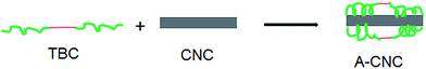 |
| | Fig. 2 Schematic illustration of the surface adsorption mechanism of the (PEO–PPO–PEO) triblock copolymer on cellulose nanocrystals. | |
Atomic force microscopy observation. The morphology of CNC and A-CNC was observed by using AFM and the results are shown in Fig. 3. The AFM image of CNC is shown in Fig. 3a and the length and diameter of the nanorods were in the range of 24–195 nm and 2–9 nm, respectively. The TBC-adsorbed CNC can be seen in Fig. 3b. The triblock copolymer formed a layer on the surface of CNC that can be seen in low magnification image. The high magnification image showed that the individual nanocrystal morphology was different compared to neat CNC. This can be attributed to the adsorption of hydrophilic ends of TBC on CNC. The size of the A-CNC was increased 2–3 nm in width due to the adsorption of TBC.
 |
| | Fig. 3 AFM images for (a) CNC, and (b) A-CNC. | |
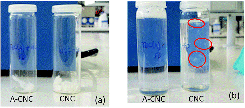
Dispersion of CNC/A-CNC in aqueous medium. Freeze-dried CNC and A-CNC were redispersed in water and the visual appearance of the samples before and after dispersion in water can be seen in Fig. 4a and b, respectively. It is obvious that CNC cannot redisperse in water after drying due to the strong hydrophilic interactions that are established between the surface hydroxyl groups and aggregates (circled in red) as can be seen in Fig. 4b. On the contrary, A-CNC was dispersed uniformly as shown in Fig. 4b. It is thus clearly shown that TBC adsorbed on the surface of CNC can swell in water and consequently the remaining CNC can be freely dispersed for naked eye observation.
 |
| | Fig. 4 (a) Freeze-dried and (b) redispersed in water CNC and A-CNC. | |
Flow properties of CNC/A-CNC aqueous dispersions. The capability of CNC to adsorb PEO–PPO–PEO polymeric chains can be investigated by studying the rheological behaviour of nanocrystal suspensions in the presence of TBC as reported in previous studies.8,21,27 In the present study, suspensions with a constant TBC concentration of 1 wt% and gradual increase of CNC content from 1 to 9 wt% were prepared and the evolution of their viscosity vs. shear rate was determined. As shown in Fig. 5, the TBC solution displays the lowest viscosity. The suspensions with low CNC contents (TBC 1% + CNC 1% and TBC 1% + CNC 2%) presented a similar behaviour as the one of neat CNC suspension, which indicates that TBC can be adsorbed on CNC surface. It indicates that the capability of surface adsorption of CNC is around 0.5–1 g of TBC for 1 g of pristine CNC. This value is lower than for PEO homopolymer with a similar molecular weight,27 probably because of a different chain conformation of the copolymer at the cellulosic surface. It justifies the 1:1 ratio used for CNC:TBC in the present study. For higher CNC contents, the viscosity increased when increasing the CNC content as expected because free CNC is released in the suspension. Moreover, shear thinning behaviour is observed and this phenomenon is emphasized as the nanoparticle concentration increases.
 |
| | Fig. 5 Evolution of the viscosity as a function of shear rate for aqueous suspensions: (●) TBC 1% + CNC 0%, (○) CNC 1%, (▲) TBC 1% + CNC 1%, (△) TBC 1% + CNC 2%, (■) TBC 1% + CNC 3%, (□) TBC 1% + CNC 4%, (╳) TBC 1% + CNC 5%, (♦) TBC 1% + CNC 7%, (◇) TBC 1% + CNC 9%. | |
SAXS experiments. Fig. 6a and b show the radial average experimental curves obtained for neat CNC and A-CNC suspensions, respectively, at concentrations of 0.1 and 0.5 wt%. These curves basically give the scattering information about the elements of the suspension at different magnifications. For higher q values the signal arises from the whole scattering objects and for lower q values it comes from their mutual interactions. The effect of concentration on the structural organization in chiral nematic phase was studied in a previous work.29 The average separation distance between the CNCs has been determined for a concentration domain ranging from 1.3 to 6.5 vol% which corresponds to 2.08 to 10.4 wt%. The results obtained in the present work correspond to very dilute samples (0.1 and 0.5 wt%) in the isotropic phase. At 0.5 wt% the scattering intensity exhibits a shoulder at q = 0.045 nm−1. We can evaluate an approximate inter-particle distance d = 2π/q = 140 nm, which is much larger than the diameter of CNC and explains why there is no change in the scattering curve within the analysed low concentration range for the suspension without (Fig. 6a) or with adsorbed polymer (Fig. 6b).
 |
| | Fig. 6 SAXS characterization of CNC suspensions: scattering intensity as a function of scattering vector for suspensions at concentration of 0.5 and 0.1 wt%: (a) neat CNC, and (b) A-CNC. | |
Fig. 7a shows a comparison of the radial average experimental curves for the 0.5 wt% CNC suspension before and after TBC adsorption. It is interesting to mention that the scattering intensity is the same for the 0.5 wt% CNC and A-CNC on a wide range of q vectors corresponding to the form factor of the particles, and that a clear change in scattering intensity is detected at lower q vector values below q = 0.045 nm−1. At high scattering vector the scattering intensity is the same before and after adsorption because adsorption is not changing the overall dimensions of the CNC. For lower q vectors (below q = 0.045 nm−1) the A-CNC suspension exhibits an increase in scattering intensity which can be attributed to a change in mutual interactions between the adsorbed cellulose nanocrystals, while no similar effect is detected for neat CNC. Furthermore, the inter-particle distance at q = 0.045 nm−1 evaluated for neat CNC is emphasised on the 2D SAXS pattern by the presence of a ring which is no more valid for A-CNC as shown in Fig. 7b.
 |
| | Fig. 7 SAXS characterization of CNC suspensions: (a) scattering intensity as a function of scattering vector for CNC and A-CNC suspensions at concentration of 0.5 wt%, and (b) two-dimensional SAXS pattern for 0.5 wt% CNC and A-CNC suspensions at SD = 10 m. | |
The absence of this inter-particle regular distance could be interpreted by the fact that the presence of the copolymer homogeneously dispersed the nanoparticles without regular spacing pertaining to primary aggregates which at higher concentrations give rise to the chiral nematic organization. It is worth noting that this work consists of a preliminary study and future investigation will be conducted at higher concentrations for both neat and adsorbed cellulose nanocrystals.
FTIR experiments. FTIR spectroscopy was used to investigate the functional properties of neat CNC, TBC and A-CNC. The results are shown in Fig. 8. Before the adsorption of TBC on CNC, the FTIR spectrum for neat CNC displayed several bands characteristic of cellulose at 3350 cm−1 (O–H), 2868 and 2970 cm−1 (C–H from –CH2–). The bands at 2970 and 1373 cm−1 for TBC correspond to the existence of methyl groups in the PEO–PPO–PEO block copolymer. The antisymmetric C–H stretching vibration of methyl groups in PPO blocks can be seen at 2970 cm−1 and 1373 cm−1 band confirming the symmetric deformation band of methyl groups.30,31 Importantly, bands at 1360 and 1108 cm−1 correspond to the CH2-wagging and C–O–C stretching, respectively, between the PEO and PPO blocks.30–32
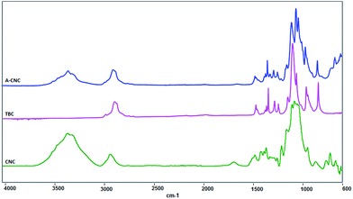 |
| | Fig. 8 FTIR spectra for CNC, TBC and A-CNC. | |
For A-CNC a substantial increase of the magnitude of the band at 2970 cm−1 corresponding to symmetric –CH2– stretches from copolymer is observed. The signal associated with the vibration of adsorbed water at 1650 cm−1 strongly decreased after surface adsorption with TBC. This might be due to the hydrophobic behaviour of the PPO block which is away from the CNC surface as shown in Fig. 2. Moreover, the bands appearing at 1360 and 1108 cm−1 correspond to TBC. Hence it is evident that the PEO–PPO–PEO block copolymer is present at the surface of CNC.
Thermal stability. The thermal degradation behaviour of freeze-dried CNC and A-CNC was investigated by TGA measurements. The results of weight loss and dTG as a function of temperature are reported in Fig. 9a and b, respectively. Neat CNC displays a slight weight loss from 30 to 130 °C. It is attributed to the presence of water due to the hydrophilic character of cellulose. This effect was decreased for the triblock copolymer-adsorbed sample (A-CNC) showing its more hydrophobic nature. It is ascribed to a lower accessibility of –OH groups after TBC surface adsorption. Then, a sharper weight loss is observed in the range 250–300 °C for CNC whereas in the case of A-CNC the weight loss is observed over a broader temperature range between 250 and 400 °C. The relative dTG curves corresponding to CNC and A-CNC (Fig. 9b) clearly indicate that the main degradation temperature for CNC is slightly lower than for A-CNC. It shows further that the surface of CNC is adsorbed with the triblock copolymer. The thermal decomposition temperatures, associated to weight loss and maximum of derived signal, were determined and results are collected in Table 1.
 |
| | Fig. 9 (a) TGA and (b) dTG curves for CNC (dashed line) and A-CNC (solid line). | |
Table 1 Temperature values at different relative weight loss for neat CNC and A-CNC
| Sample |
Temperature (°C) at different relative weight loss |
| 10% |
20% |
40% |
60% |
| CNC |
227 |
284 |
298 |
316 |
| A-CNC |
238 |
289 |
304 |
398 |
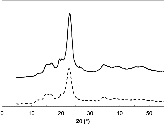
X-ray diffraction. The crystallinity of neat CNC and A-CNC was investigated by X-ray diffraction and the patterns are shown in Fig. 10. The diffraction peaks for CNC at 22.6°, 14.8°, 16.4°, and 34.4° were assigned to the typical reflection planes of cellulose I.33 In the case of TBC-adsorbed CNC (A-CNC) new crystalline peaks are observed at 2θ = 19.2° and around 26–27° ascribed to PEO chains8 present in the triblock copolymer. Interestingly the intensity at 16.8° increases after adsorption of TBC confirming that the surface of CNC was adsorbed with PEO–PPO–PEO.
 |
| | Fig. 10 X-ray diffraction patterns for CNC (dashed line) and A-CNC (solid line). | |
CNC reinforced nanocomposites
Neat CNC and TBC-adsorbed CNC reinforced LLDPE nanocomposites were prepared by twin-screw extrusion as detailed in the Experimental section. The aspect of resultant nanocomposite films is shown in Fig. 11. The neat PE film is translucent as any low thickness semi crystalline polymeric film. When adding only 5 wt% CNC, the film becomes homogeneously darker. This dark colouration after extrusion is a clear indication of the thermal degradation of the cellulosic filler.21,27 The appearance of the nanocomposite films reinforced with up to 10 wt% A-CNC is similar to that of the neat PE film. This observation agrees with TGA experiments and could be related to the protection of sulphate groups provided by adsorbed TBC.
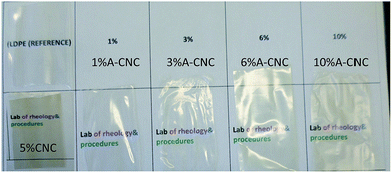 |
| | Fig. 11 Appearance of extruded CNC/LLDPE and A-CNC/LLDPE nanocomposite films. | |
Thermal properties. The thermal characterization of CNC/A-CNC reinforced LLDPE nanocomposite films was carried out using DSC. From the analysis of DSC traces, the melting temperature (Tm), associated heat of fusion (ΔHm) and degree of crystallinity (χC) were obtained for the unfilled LLDPE film and nanocomposite materials reinforced with either CNC or A-CNC. The resulting experimental data are listed in Table 2.
Table 2 Melting characteristics of LLDPE based nanocomposites reinforced with CNC or A-CNC obtained from DSC measurements: melting temperature (Tm), enthalpy of fusion (ΔHm) and degree of crystallinity (χC)
| Sample |
Tm (°C) |
ΔHm (J g−1) |
χCa |
 where w is the weight fraction of polymeric matrix in the composite and where w is the weight fraction of polymeric matrix in the composite and  (heat of fusion for 100% crystalline LLDPE). (heat of fusion for 100% crystalline LLDPE). |
| LLDPE |
118.0 |
117.4 |
40.5 |
| LLDPE + 1% A-CNC |
117.4 |
121.5 |
41.9 |
| LLDPE + 3% A-CNC |
117.5 |
128.9 |
44.4 |
| LLDPE + 6% A-CNC |
119.9 |
113.9 |
39.3 |
| LLDPE + 10% A-CNC |
120.1 |
117.0 |
40.3 |
| LLDPE + 5% CNC |
118.0 |
99.35 |
34.3 |
The melting point remained roughly constant between 117 and 120 °C upon A-CNC or CNC addition. It indicates that the size of the crystallites was not affected by the filler. On the contrary, the degree of crystallinity of LLDPE was slightly increased for low A-CNC contents (1 and 3 wt%). This effect is classically observed for CNC reinforced semi-crystalline polymers and is generally attributed to a nucleating effect of the cellulosic nanoparticle. For higher A-CNC contents (6 and 10 wt%) the degree of crystallinity of LLDPE crystallinity showed lower values and was similar to that of the neat matrix. It could possibly result from a competitive effect between the nucleating effect of A-CNC and increase of the viscosity of the medium that limits the crystallization of the matrix. Similar behaviour has been reported for CNC reinforced PEO.34 LLDPE reinforced with 5 wt% neat CNC displays a very low degree of crystallinity compared to neat LLDPE. It seems reasonable to speculate that aggregation and limited filler/matrix interface, as well as thermal degradation of the cellulosic nanofiller, are responsible for this phenomenon.
Mechanical properties. Fig. 12 shows the evolution of the logarithm of the storage modulus as a function of temperature for CNC/A-CNC reinforced LLDPE nanocomposites. The behaviour of the neat matrix has been added in the figure for reference. The modulus is roughly constant in the low temperature range but it drops around −40 °C due to the anelastic manifestation of the glass transition of the polymeric matrix. For higher temperatures the modulus gradually decreases because of the progressive melting of the polymer. At the melting temperature of the polymeric matrix, the modulus dropped sharply and the setup fails to measure it due to irreversible chain flow.
 |
| | Fig. 12 Evolution of the logarithm of the storage tensile modulus as a function of temperature for the neat and LLDPE nanocomposites: (●) LLDPE, (○) LLDPE + 5% CNC, (▲) LLDPE + 1% A-CNC, (△) LLDPE + 3% A-CNC, (■) LLDPE + 6% A-CNC, (□) LLDPE + 10% A-CNC. | |
No significant difference is reported between the unfilled LLDPE and nanocomposites in the glassy state of the matrix as expected because of the stiffness of the matrix in this temperature range. At higher temperatures differences are observed and it is clearly seen that the rubbery modulus of the nanocomposite reinforced with 5 wt% neat CNC is lower than that of the matrix. This might be because of the degradation and poor dispersion of CNC. The lower degree of crystallinity of the sample should also, at least partially, participate to this effect. While adding A-CNC, the rubbery modulus significantly increased possibly ascribed to a reinforcing effect of the nanofiller. Improved dispersion of the nanoparticles and favourable interactions with the matrix, but also increased crystallinity of the matrix, are most probably responsible for this effect. It is worth noting that the modulus of the nanocomposite is practically independent of the filler content. It is usually difficult to separate the impact of the CNC-induced crystallization and real reinforcing effect of the nanofiller, but in our case since the degree of crystallinity of the neat matrix and highly filled nanocomposites (6 and 10 wt% A-CNC) are similar (see Table 2), the higher rubbery modulus of the nanocomposites can be unambiguously attributed to a reinforcing effect of the cellulose nanorods. It is worth noting that this reinforcing effect is much higher than that observed for PE nanocomposites reinforced with CNC coated with PEO homopolymer.27
Morphological investigation. The cryo-fractured cross section of the nanocomposite films was investigated by SEM (Fig. 13). By comparing Fig. 13a (neat LLDPE matrix) and Fig. 13b (LLDPE reinforced with 5 wt% CNC), the presence of the nanofiller results in the observation of microscopic holes. These holes most probably correspond to CNC aggregates formed during drying because of hydrogen bonding between individual CNC, that have been degraded during melt processing at 160 °C. The cross section of nanocomposites reinforced with A-CNC (Fig. 13c–f) is similar to that of the neat matrix showing the homogeneous dispersion of the nanofiller within the matrix. These observations corroborate the mechanical properties obtained for these materials.
 |
| | Fig. 13 SEM images of the cryo-fractured cross section for extruded films: (a) neat LLDPE, and LLDPE nanocomposites reinforced with (b) 5 wt% CNC, and (c) 1, (d) 3, (e) 6 and (f) 10 wt% A-CNC. | |
SAXS characterization. Fig. 14 compares the evolution of the scattering intensity as a function of scattering vector for PE + 5% CNC and PE + 6% A-CNC nanocomposites. A slight variation can be seen between both samples which is due to the slightly different nanofiller content. The inserted images are the scattering patterns corresponding to these samples. Significant difference can be seen between neat CNC and TBC-adsorbed CNC reinforced nanocomposites. The 2D scattering pattern is more anisotropic for PE + 6% A-CNC. This can be ascribed to the difference in the dispersion state of CNC in the matrix before and after TBC adsorption. The PE + 5% CNC nanocomposite displays poor dispersion, whereas the nanofiller in PE + 6% A-CNC has a more uniform dispersion, agreement with SEM observations.
 |
| | Fig. 14 SAXS characterization of CNC and A-CNC reinforced LDPE nanocomposite films: scattering intensity as a function of scattering vector for LDPE + 6% A-CNC (╳), LDPE + 5% CNC (♦) and corresponding 2D-SAXS patterns. | |
Fig. 15 shows the 2D-SAXS patterns for A-CNC nanocomposites with different nanofiller contents varying from 1 to 10 wt%. The SAXS patterns exhibit an anisotropic shape with a higher intensity in the horizontal direction which corresponds to a preferential orientation of A-CNC in the flow direction during the extrusion process. For increasing A-CNC content, the anisotropic level is amplified which could be attributed to a higher orientation of the nanorods or to an increasing quantity of A-CNC nanoparticles orientated in the flow direction during the extrusion process.
 |
| | Fig. 15 2D SAXS patterns for LDPE nanocomposites with different A-CNC contents. | |
Conclusions
In this study we have developed an efficient and simple water based method to prepare cellulose nanocrystal (CNC) reinforced polyethylene nanocomposites by melt processing. It consists in coating the nanoparticle (ratio 1:1) with a triblock copolymer (TBC) having two hydrophilic ends attached to a hydrophobic central block. The hydrophilic ends were expected to interact with the cellulosic surface leaving the hydrophobic block free to provide compatibility with the polyethylene matrix chains. Coating of CNC with the copolymer was visualized from AFM observations and the rheological behaviour of aqueous dispersions indicates that the surface adsorption capability of CNC is around 1–2 g of TBC for 1 g of pristine CNC. Moreover, this coating allows a much easier and better redispersion in water of the nanoparticles after freeze-drying, that was also characterized by SAXS experiments, and improves their thermal stability. After melt extrusion with polyethylene, the visual appearance of films prepared from TBC-coated CNC was clearly indicative of an improved dispersion, that was also evidenced from SEM observations, and limited thermal degradation. It results in significantly improved mechanical properties for the nanocomposites. SAXS experiments show a much more prominent preferential orientation and alignment in the flow direction for TBC-coated CNC compared to neat CNC which is induced by the extrusion step. It further indicates that individual coated nanorods are present in the nanocomposite films.
Acknowledgements
LGP2 and LRP are part of the LabEx Tec 21 (Investissements d'Avenir – grant agreement no. ANR-11-LABX-0030) and of the PolyNat Carnot Institut (Investissements d'Avenir – grant agreement no. ANR-11-CARN-030-01). We gratefully acknowledge Theyencheri Narayanan for the support with SAXS measurements and the ESRF for beam time allocation.
References
- M. A. S. Azizi Samir, F. Alloin and A. Dufresne, Biomacromolecules, 2005, 6, 612 CrossRef PubMed.
- Y. Habibi, A. L. Lucia and O. J. Rojas, Chem. Rev., 2010, 110, 3479 CrossRef CAS PubMed.
- D. Klemm, F. Kramer, S. Moritz, T. Lindström, M. Ankerfors, D. Gray and A. Dorris, Angew. Chem., Int. Ed., 2011, 50, 5438 CrossRef CAS PubMed.
- R. J. Moon, A. Martini, J. Nairn, J. Simonsen and J. Youngblood, Chem. Soc. Rev., 2011, 40, 3941 RSC.
- N. Lin and A. Dufresne, Biomacromolecules, 2013, 14, 871 CrossRef CAS PubMed.
- A. Dufresne, Molecules, 2010, 15, 4111 CrossRef CAS PubMed.
- S. J. Eichhorn, A. Dufresne, M. Aranguren, N. E. Marcovich, J. R. Capadona, S. J. Rowan, C. Weder, W. Thielemans, M. Roman, S. Renneckar, W. Gindl, S. Veigel, J. Keckes, H. Yano, K. Abe, M. Nogi, A. N. Nakagaito, A. Mangalam, J. Simonsen, A. S. Benight, A. Bismarck, L. A. Berglund and T. Peijs, J. Mater. Sci., 2010, 45, 1 CrossRef CAS.
- N. Lin and A. Dufresne, Macromolecules, 2013, 46, 5570 CrossRef CAS.
- N. Lin, J. Huang and A. Dufresne, Nanoscale, 2012, 4, 3274 RSC.
- K. L. Dagnon, K. Shanmuganathan, C. Weder and S. J. Rowan, Macromolecules, 2012, 45, 4707 CrossRef CAS.
- J. D. Fox, J. R. Capadona, P. D. Marasco and S. J. Rowan, J. Am. Chem. Soc., 2013, 135, 5167 CrossRef CAS PubMed.
- N. Lin and A. Dufresne, Nanoscale, 2014, 6, 5384 RSC.
- A. Dufresne, Nanocellulose: From nature to high performance tailored materials, Walter de Gruyter GmbH, Berlin and Boston, MA, 2012 Search PubMed.
- F. Alloin, A. D'Aprea, A. Dufresne, N. El Kissi and F. Bossard, Cellulose, 2011, 18, 957 CrossRef CAS.
- W. J. Orts, J. Shey, S. H. Imam, G. M. Glenn, M. E. Guttman and J. F. Revol, J. Polym. Environ., 2005, 13, 301 CrossRef CAS.
- A. L. Goffin, J. M. Raquez, E. Duquesne, G. Siqueira, Y. Habibi, A. Dufresne and P. Dubois, Biomacromolecules, 2011, 12, 2456 CrossRef CAS PubMed.
- A. L. Goffin, J. M. Raquez, E. Duquesne, G. Siqueira, Y. Habibi, A. Dufresne and P. Dubois, Polymer, 2011, 52, 1532 CrossRef CAS.
- A. J. de Menezes, G. Siqueira, A. A. S. Curvelo and A. Dufresne, Polymer, 2009, 50, 4552 CrossRef CAS.
- J. M. Raquez, Y. Murena, A. L. Goffin, Y. Habibi, B. Ruelle, F. DeBuyl and P. Dubois, Compos. Sci. Technol., 2012, 72, 544 CrossRef CAS.
- S. H. Xu, J. Gu, Y. F. Luo and D. M. Jia, eXPRESS Polym. Lett., 2012, 6, 14 CrossRef CAS.
- K. Ben Azouz, E. C. Ramires, W. van den Fonteyne, N. El Kissi and A. Dufresne, ACS Macro Lett., 2012, 1, 236 CrossRef CAS.
- E. Fortunati, I. Armentano, Q. Zhou, A. Iannoni, E. Saino, L. Visai, L. A. Berglund and J. M. Kenny, Carbohydr. Polym., 2012, 87, 1596 CrossRef CAS.
- Q. Zhou, H. Brumer and T. T. Teeri, Macromolecules, 2009, 42, 5430 CrossRef CAS.
- K. Oksman, A. P. Mathew, D. Bondeson and I. Kvien, Compos. Sci. Technol., 2006, 66, 2776 CrossRef CAS.
- D. Bondeson and K. Oksman, Composites, Part A, 2007, 38, 2486 CrossRef.
- M. Nagalakshmaiah, N. El Kissi and A. Dufresne, ACS Appl. Mater. Interfaces, 2016, 8, 8755 CAS.
- M. Pereda, N. El Kissi and A. Dufresne, ACS Appl. Mater. Interfaces, 2014, 6, 9365 CAS.
- Y. Li, H. Liu, J. Song, O. J. Rojas and J. P. Hinestroza, ACS Appl. Mater. Interfaces, 2011, 3, 2349 CAS.
- C. Schütz, M. Agthe, A. B. Fall, K. Gordeyeva, V. Guccini, M. Salajková, T. S. Plivelic, J. P. F. Lagerwall, G. Salazar-Alvarez and L. Bergström, Langmuir, 2015, 31, 6507 CrossRef PubMed.
- M. A. K. L. Dissanayake and R. Frech, Macromolecules, 1995, 28, 5312 CrossRef CAS.
- N. Kimura, J. Umemura and S. Hayashi, J. Colloid Interface Sci., 1996, 182, 356 CrossRef CAS.
- S. Yan-lei, W. Jing and L. Hui-zhou, Langmuir, 2002, 18, 5370 CrossRef.
- H. Liu, D. Liu, F. Yao and Q. Wu, Bioresour. Technol., 2010, 101, 5685 CrossRef CAS PubMed.
- M. A. S. Azizi Samir, F. Alloin, J. Y. Sanchez and A. Dufresne, Polymer, 2004, 45, 4149 CrossRef CAS.
|
| This journal is © The Royal Society of Chemistry 2016 |
Click here to see how this site uses Cookies. View our privacy policy here. 


 where w is the weight fraction of polymeric matrix in the composite and
 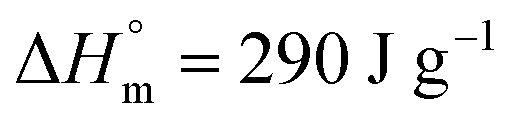 (heat of fusion for 100% crystalline LLDPE).


