Mechanical and thermal properties of toluene diisocyanate-modified cellulose nanocrystal nanocomposites using semi-crystalline poly(lactic acid) as a base matrix

Jae-Gyoung Gwona, Hye-Jung Choa, Sang-Jin Chuna, Soo Leeb, Qinglin Wuc, Mei-Chun Lic and Sun-Young Lee*a
aNational Institute of Forest Science, Department of Forest Products, Seoul, 02455, Korea. E-mail: nararawood@korea.kr
bChangwon National University, Department of Chemical Engineering, Changwon, 51140, Korea
cLouisiana State University Agricultural Center, School of Renewable Natural Resources, Baton Rouge, LA 70803, USA

Received 28th April 2016 , Accepted 10th July 2016

First published on 19th July 2016


Abstract

Although chemical modifications (grafting ‘onto’) of CNCs have been successfully adopted to enhance their dispersibility in apolar matrices and solvents, the problem of the dispersion level of mCNCs (chemically modified CNCs) in apolar matrices above a certain loading of nanoparticles remains an issue. CNCs were successfully modified using toluene diisocyanate, and the effects of the molar mass (Mw) and crystallinity (Xc) of semicrystalline poly(lactic acid) (PLA) on the mechanical and thermal properties of mCNC filled PLA nanocomposites were investigated. An increase in the mechanical properties of the PLA nanocomposites with mCNCs implied that Mw and Xc of PLA can be key factors to improve the dispersion level of mCNCs. In our solvent dilute polymer system, despite a reduction in the crystallinity of PLA with increasing mCNC loading level, the melting temperature of the PLAs remained constant due to the mCNC effect, which hinders the chain mobility of the PLAs. The results demonstrated that a fundamental understanding of the crystallinity and molar mass of polymers as well as surface modification of CNCs can be a reasonable approach to take full advantage of the potential usage of CNCs as reinforcements.

1. Introduction

Commercial polymers have an enormous effect on human life because of their wide range of advantages, such as versatile mechanical properties, high productivity, ease of processing and recycling capability.1 With increased environmental concerns, however, it is inevitable that the use of compostable biopolymers should gain increasing interest. Since poly(lactic acid) (PLA) has similar fundamental properties to petroleum-based thermoplastics, it is an excellent alternative candidate to commodity polymers.2 PLA is usually manufactured from completely renewable resources, such as corn starch, sugar beets, or rice.3 Nano-sized celluloses [cellulose nanocrystals and nanofibers (CNCs and CNFs)] have recently attracted much attention in nanotechnology fields.4–15 CNCs show unique properties, such as low density (1.6 g cm−3),16 high surface area (300 m2 g−1),10 and outstanding tensile strength (7.5 to 7.7 GPa)16 due to their nanoscale size and high crystallinity. In addition, the abundant hydroxyl groups on the surface of CNCs facilitate the achievement of desired surface characteristics through various surface grafting strategies.17,18 Furthermore, surface chemical modification enables the application of CNCs to an extensive spectrum of polymers, from hydrophilic to hydrophobic.4,14,19–23 For these appealing reasons, we have focused our attention on the study of CNCs as a bio-filler for polymer nanocomposites.

It is essential to achieve good dispersion of nanoparticles in an apolar matrix to take full advantage of nano-sized celluloses as reinforcements.24 Recently, a large number of studies on chemical grafting onto the surface of nanocelluloses have been performed with the aim of improving the dispersibility of the nanoparticles in apolar matrices and solvents. The surface modulation is mainly achieved via five strategies for the pre-treatment methods: (i) urethanization,22,25–27 (ii) silylation,8,12,28–31 (iii) amidation,32 (iv) acetylation,19 and (v) polymer grafting (‘onto’ or ‘from’).33,34 Particularly, urethanization can be used in various chemical reactions because the isocyanate (–NCO) group has high reactivity with various functionalities, such as amino (–NH2), hydroxyl (–OH), and carboxylic acid (–COOH) groups.35,36 Although urethanization is obviously a useful strategy for surface modification, only a few literature reports22,25–27,35 have employed this strategy for surface tuning. Therefore, one of the aims of the present study is to provide practical information regarding urethanization using toluene diisocyanate (TDI) for extensive usage of nanocelluloses in the nanocomposite field.

In solvent casting systems, high loading levels of mCNCs can sometimes have detrimental effects on the mechanical properties of the nanocomposites. A few studies12,35 have accomplished improvements in the mechanical strength of PLA nanocomposites with the addition of only 1 wt% mCNCs in the system. Although the dispersibility of CNCs in the polymer matrix is improved through chemical modifications, the mCNCs can agglomerate again as the mCNCs loading level increases. Namely, interactions between mCNCs can be physically strong due to high loading (>1 wt%) of the CNCs; thus, the mechanical properties of polymer composites containing CNCs can decrease.35 It is commonly believed that an overdose of filler in the matrix leads to severe agglomeration, resulting in a reduction of the mechanical properties of the final composites due to the flocculation phenomenon.35,37,38 To address the limitations of the chemical dispersion method, it is hypothesized that crystal domains in semi-crystalline polymers can help prevent the flocculation of CNCs.

Generally, it is difficult to completely dissolve the crystal domains in a dilute solution system without additional heat energy to overcome the enthalpy of crystallization.39 This consideration can also be used to explain why a solvent casting method was adopted in our present research. To the best of our knowledge, no efforts have been made to further improve the dispersibility of mCNCs by using crystal domains for enhancing the mechanical properties of the end products. The main objective of this study is to explore the effects of the crystallinity (Xc) and molar mass (Mw) of PLA on the dispersibility of TDI modified CNCs in the matrices and on the mechanical and thermal properties of mCNC filled PLA nanocomposites.

2. Experimental

2.1. Materials

Powdered cellulose (grade: W-50, KC Flock), used as the source of the CNCs, was purchased from Nippon Paper Chemicals Co., Ltd., Japan. Its average particle size and bulk density are 45 μm and 0.15 to 0.2 g cm−3. Three grades (Ingeo™ 2003D, 3001D, and 4032D) of poly(lactic acid) (PLA) were supplied from Natureworks LLC, USA. The specific information for all PLA grades used for the nanocomposites is summarized in Table 1. Toluene diisocyanate (TDI, 2,4-TDI[thin space (1/6-em)]:[thin space (1/6-em)]2,6-TDI = 80[thin space (1/6-em)]:[thin space (1/6-em)]20, Alfa Aesar, USA) was applied to achieve good dispersion of the CNCs in the PLA matrix and apolar solvent. 64 wt% diluted sulfuric acid was used for acid hydrolysis of the cellulose. Acetone (Ac), N,N-dimethylformamide (DMF), dichloromethane (DCM), and chloroform (CF) (HPLC grade, from Daejung Chemicals Co., Ltd., Korea) were used as received for the solvent exchange. Deionized water (DI-water, resistivity > 18 MΩ) was used for acid hydrolysis.
Table 1 Characteristics of commercial PLA grades
Grade D-Lactide (%) Mna (kDa) Mwa (kDa) PDIb Crystallinityc (%)
a Results from GPC.b Polydispersity index (PDI): Mw/Mn.c Results from DSC.
2003D 4 to 4.5 (ref. 52) 23.2 169 7.30 33.5
3001D 1.6 (ref. 53) 13.7 107 7.80 44.8
4032D 1.4 (ref. 49) 20.7 160 7.69 44.5


2.2. Preparation and chemical modification of CNCs

The CNCs were prepared following a protocol described in the literature.35 21 g of dried cellulose powders (at 80 °C for 24 h) were hydrolyzed in 350 ml of 64 wt% sulfuric acid at 45 °C for 45 min at 230 rpm. After the hydrolysis, the suspension was quickly poured into 2500 ml DI-water to stop the hydrolysis reaction. The supernatant was removed after 12 h; fresh DI-water was then poured into the residual sediment, and the decanting step was repeated twice over 24 h. After removal of the supernatant, the collected sediment was neutralized by adding 10 M NaOH solution. The neutralized CNC slurry was centrifuged, and the CNCs were then re-dispersed in DI-water. For further chemical functionalization steps, the aqueous suspension of CNCs was solvent-exchanged to Ac, and the CNC suspension in Ac was then stored at −10 °C in a refrigerator.

The urethanization strategy was carried out for CNC surface modification as described in a previous study.35 The Ac suspension of CNCs was solvent-exchanged to DCM and then to DMF. The DMF suspension of CNCs (0.01 g ml−1) was added to a three-neck flat-bottomed flask with a reflux condenser under nitrogen atmosphere, and the flask was immersed in a silicon oil bath preheated to 70 °C. A stable DMF-CNC suspension was achieved after 30 min at 70 °C; TDI was slowly added to the suspension dropwise with an NCO index of 2 (2[thin space (1/6-em)]:[thin space (1/6-em)]1 equivalent ratio of isocyanate groups in TDI to total hydroxyl groups in the desired CNCs). TDI was grafted onto the CNCs surface for 24 h, and then DMF was exchanged to CF. Subsequently, the CNC suspension in CF was sonicated (VCX 130 sonicator, Sonics & Materials Inc.) for 15 min four times in an ice bath to achieve a homogeneous suspension. Each solvent exchange was performed by four successive centrifugations (at 7000 rpm at 10 °C for 300 s) and redispersion steps (at 10[thin space (1/6-em)]000 rpm for 15 s) using a high speed refrigerated centrifuge (Mega 17R, Hanil Science Industrial) and a homogenizer (Ultra Turrax® T25, IKA®), respectively.

2.3. PLA/CNC nanocomposite preparation

PLA nanocomposite films with TDI grafted CNCs (mCNCs) were prepared by a doctor blade casting method. 6 g of PLA was dissolved in 40 ml of CF suspension of mCNCs (1, 3, 5, 7, and 9 wt% compared to PLA weight) with magnetic stirring (200 rpm) at room temperature for 24 h. The dissolved solution was casted onto a glass substrate with A4 size, and the slow evaporation method40 was performed for 24 h. After the evaporation, the nanocomposite films were dried in an oven at 85 °C for 24 h to eliminate residual solvent. Subsequently, the PLA film was cooled to room temperature and peeled from the glass substrate; its thickness was approximately 101 μm.

2.4. Characterizations

The sizes of the pristine CNCs prepared by acid hydrolysis and the mCNCs were examined using a transmission electron microscope (JEM 1400, JEOL, Japan) at a 120 kV accelerating voltage. 30 measurements of CNCs and mCNCs from a TEM image were randomly chosen using Image Pro Plus software (Media Cybernetics Inc.) to calculate the average sizes in length and width of the obtained nanoparticles.

A scanning electron microscope (SEM, EM-30, COXEM Co. Ltd., Korea) was used to analyze the surface topographies of the PLA nanofilms at 30 kV.

Gel permeation chromatography (GPC) was performed to evaluate the molar masses (Mw) of the polymers (PLA Ingeo™ 2003D, 3001D, and 4032D) using a Waters GPC system with a pump (Waters 515), a detector (Waters 410 Differential Refractometer), and two columns (Shodex LF-804) using polystyrene standards. The Mw of each PLA grade was examined at 40 °C with CF as the mobile phase (1.0 ml min−1).

The carbon, hydrogen, nitrogen, oxygen, and sulfur contents of CNC and mCNC were determined by an elemental analyzer (vario MACRO cube, Elementar, Germany). The degree of substitution (DS, the number of grafted hydroxyl groups per anhydroglucose unit) for mCNC was calculated using the following equation:25,27

 
image file: c6ra10993d-t1.tif(1)
where % C is the normalized carbon content based on the theoretical value of the weight ratio between the carbon and oxygen atoms.25 Also, Am, Am, Tm, and Tm correspond to the carbon mass of the anhydroglucose unit, the total mass of the anhydroglucose unit, the carbon mass of toluene diisocyanate, and the total mass of toluene diisocyanate, respectively. The measurement was carried out twice and the mean value was used. The results are shown in Fig. S1 (ESI), and the DS of the TDI-modified CNC was 0.12.

The crystalline structures of the CNCs and mCNCs were explored using X-ray diffraction (XRD, D8 ADVANCE) with a Cu Kα radiation source (λ: 0.154 nm) at an operating voltage and current of 40 kV and 40 mA, respectively. XRD patterns (Fig. S2) were obtained with a 2θ (Bragg angle) scan range from 10° to 40° in steps of 0.02° at room temperature. The crystallinities (Cr, %) of CNC and mCNC were calculated using the XRD amorphous subtraction method (Ruland–Vonk method).41 The calculated crystallinities of the CNCs and mCNCs were 60.9 and 56.8%, respectively. The slight decrease in crystallinity after the TDI modification may be due to the introduction of a slight disordered region on the surface of the CNC nanoparticles, as reported elsewhere.22

To clarify the chemical structure of the modified CNCs, solid-state 13C cross polarization-magic angle spinning (CP-MAS) NMR measurements were carried out (Bruker Avance 400WB, USA) operating at 9.39 T at room temperature. The magic angle spinning rate was 12 Hz, and a 2.5 mm probe was utilized.

Fourier transformed infrared spectroscopy (FTIR, Nicolet™is™10 FT-IR Spectrometer, Thermo Scientific, USA) with an attenuated total reflectance (ATR) accessory was used to analyze the surface chemistry of the CNCs. The FTIR spectra were obtained from 16 scans with a resolution of 4 cm−1 under forced conditions. A background file was recorded prior to each scan at 4 cm−1 resolution with 16 scans, and all the samples (CNC and mCNC suspension in chloroform) were dried to completely remove the solvent at 70 °C for 3 h using a convection oven before the measurements.

The tensile tests for the PLA nanofilms were conducted using a Universal Testing Machine (H50KS, Tinius Olsen, USA) with a load cell of 500 N at a crosshead speed of 10 mm min−1 according to ASTM D 638. The samples were 5 mm in width and 70 mm in length; however, the thickness of each sample was measured prior to testing. Mean values from five different specimens were obtained to determine the mechanical properties. Differential scanning calorimetry (DSC, DSC Q10, TA Instruments) was performed in nitrogen atmosphere to analyze the melting (Tm) and the enthalpy (ΔHm) of the nanocomposites. Tm and ΔHm were calibrated with indium reference material. Samples of about 6 mg were heated from 30 °C to 200 °C and then cooled to 30 °C at a rate of 10 °C min−1. The crystallinity (Xc) was calculated using the following equation:19,42,43

 
image file: c6ra10993d-t2.tif(2)
where ΔHm is the melting enthalpy of the sample, ΔHm(crys) is the melting enthalpy of 100% crystalline PLA (93 J g−1) and w is the mass fraction of the PLA in the nanocomposites. The averaged DSC results for each sample were obtained from three measurements.

3. Results and discussion

3.1. CNC isolation and TDI functionalization

Fig. 1a and b show the TEM results of the pristine CNCs and mCNCs. CNCs of about 134 ± 25 nm in length and 6.9 ± 1.7 nm in diameter are observed, as reported elsewhere.26,28,44 The mCNCs have similar length and diameter to the CNCs. Interesting changes in the morphology of the mCNCs compared to the CNCs are observed. The mCNCs have more uneven surfaces than the CNCs. This could be due to the formation of a TDI amorphous layer on the surface of the CNCs; this result is very likely related to the reduction in crystallinity of the CNCs, as explained in the Experimental section (XRD section).
image file: c6ra10993d-f1.tif
Fig. 1 (a) TEM images of (a) pristine CNCs and (b) mCNCs.

To obtain a stable suspension of CNCs in apolar solvent (chloroform) and enhance the interfacial interactions between the CNCs and the PLA matrix, TDI was covalently grafted onto the surface of pristine CNCs. Fig. 2a shows the surface changes between the CNCs and mCNCs in the FTIR spectra. The reaction between an isocyanate group (–NCO) from TDI and an alcohol group (–OH) from the CNCs leads to the initiation of the urethane (or carbamate–NHCOO) linkage. Several band intensities in the spectra are changed due to the addition reaction: (i) increase of the absorption band intensities at 1710, 1600, and 1574 cm−1, corresponding to the carbonyl (C[double bond, length as m-dash]O) stretching in the urethane group (1710 and 1574 cm−1) and the alkene (C[double bond, length as m-dash]C) stretching vibration in the toluene moiety (1600 cm−1), (ii) 2272 cm−1, corresponding to free isocyanate stretching (N[double bond, length as m-dash]C[double bond, length as m-dash]O), and (iii) 3000 to 3600 cm−1, corresponding to intermolecular hydrogen bonded O–H stretching. Fig. 2b shows the dispersibility of CNCs and mCNCs in CF at a concentration of 0.01 wt%. The CNCs immediately agglomerated in the apolar solvent after the sonication, while the mCNCs suspension remained stable after standing for 3 min. Therefore, the TDI moiety can provide greater stability to mCNCs in apolar solvent than pristine CNCs due to the improved interfacial compatibility between the solvent and the mCNC surface.


image file: c6ra10993d-f2.tif
Fig. 2 (a) FTIR-ATR spectra of CNCs and mCNCs; (b) visual appearances of CNCs and mCNCs suspensions in chloroform.

Solid state 13C NMR spectroscopy of mCNC was performed to verify the chemical structure of the TDI grafted CNCs. The recorded NMR spectrum is shown in Fig. 3. Characteristic chemical shifts of CNCs are observed near 105 (C1), 75–72 (C2, C3, and C5), 84 (C4), and 63 (C6) ppm.45 In addition, additional resonance peaks are located around 155, 136, 130, 120, and 17.8 ppm, attributed to C7 (C[double bond, length as m-dash]O in urethane), C8 (C–N), C9 (C[double bond, length as m-dash]C in the aromatic ring of TDI), C11 (N[double bond, length as m-dash]C[double bond, length as m-dash]O in TDI), and C10 (CH3 in TDI).45–47 The 13C NMR results show clear evidence of the successful grafting of TDI onto the surface of the CNCs.


image file: c6ra10993d-f3.tif
Fig. 3 13C NMR spectra of TDI modified CNCs.

3.2. Mechanical properties

Fig. 4 shows the effects of CNCs and mCNCs as reinforcements on the tensile strength of semi-crystalline PLA films. The PLA nanofilms filled with unmodified CNCs have lower tensile strength than the pure PLA films due to severe flocculation resulting from the surface incompatibility between PLA and the CNCs.35 However, the addition of mCNCs to the matrix enhances the tensile strength of the PLA nanofilms. This result is highly related to the improved dispersibility of the CNCs in the PLA matrix due to the TDI functionalization on the CNCs. In addition, there are two types of interactions between the mCNC surface and the PLA backbone: (i) covalent interactions between the PLA end groups (–OH and –COOH) and free isocyanate groups (–NCO) on the mCNC surface, which can form urethane (–NHCOO–) and amide (–CONH–) cross-links; and (ii) non-covalent interactions between the PLA backbone and the mCNC surface (hydrogen bonding and van der Waals interactions). These interactions are expected based on the FTIR measurements. Fig. 5 shows FTIR spectra of the pristine PLA film and the PLA nanofilm with mCNC. Characteristic peaks48 of pristine PLA at 1760 (1), 1500 to 1300 (5 and 6), and 1179 (7) cm−1 (attributed to C[double bond, length as m-dash]O stretching, the C–H vibration in CH3, and the C–O stretching vibration in carboxyl groups, respectively) are observed. After incorporation of mCNC in the PLA film, the intensities at the absorption bands are weak; however, the intensities of the peaks at 1710 (2), 1609 (3), and 1525 (4) cm−1 (corresponding to C[double bond, length as m-dash]O in urethane, C[double bond, length as m-dash]C in aromatic rings, and C–N in amide, respectively) are increased. The changes of intensities at the absorption peaks may be due to the interactions between the PLA backbone bonds and the mCNC surfaces, as explained above. Therefore, chemical tuning of CNCs with TDI can improve the tensile strength of PLA nanocomposites due to various intermolecular interactions and the enhanced dispersibility of the mCNCs.
image file: c6ra10993d-f4.tif
Fig. 4 Tensile strengths of PLA films showing the effects of TDI modified CNCs.

image file: c6ra10993d-f5.tif
Fig. 5 FTIR spectra of pristine PLA film and PLA nanofilm with mCNCs.

Fig. 6a shows the effects of the PLA grade on the tensile strength of the PLA nanocomposites as a function of mCNC content. A notable change is that the strengths of the 4032D PLA films are higher than those of the 2003D and 3001D PLA films. To better understand this, Fig. 7 illustrates the characteristic differences between the PLA grades based on Table 1. The 4032D PLA grade shows a higher molar mass (Mw) than the 3001D grade and a higher crystallinity (Xc) than the 2003D grade. Generally, the mechanical strength of polymers increases with increasing Mw and Xc.39 A high Mw for a polymer leads to a high degree of chain entanglement. The increased entanglement of the polymer chain enhances the intermolecular interaction between chain segments. Crystal domains in the polymer matrix also act as reinforcing agents by forming a continuous phase in the matrix. Therefore, the 4032D PLA grade, with high Mw and Xc, shows better mechanical performance than the other grades by fulfilling the conditions of high Mw and Xc.


image file: c6ra10993d-f6.tif
Fig. 6 Tensile responses ((a) strength and (b) elongation modulus) of PLA nanofilms with various PLA grades as a function of mCNC content.

image file: c6ra10993d-f7.tif
Fig. 7 Characteristic differences in PLA grades for molar mass and crystallinity.

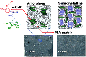
Another interesting response in the strength is observed when compared with our previous result.35 Fig. 6a demonstrates that the optimum concentrations of mCNC for the highest tensile strength are 3 wt% (for the 2003D and 3001D grades) and 5 wt% (for the 4032D grade). Compared with the pure PLA grades, the tensile strengths at the optimum loading level for the 2003D, 3001D, and 4032D PLA nanocomposites increase by 16.0%, 13.6%, and 15.3%, respectively. However, the amorphous PLA nanofilm (4060D grade) with mCNC has the optimum tensile strength at the 1 wt% loading level with an 11% increment (Fig. S4, ESI). The optimum loading level of mCNC in the semi-crystalline polymers is much higher than that in the amorphous polymer. As discussed earlier, the decrease in the mechanical properties of polymer composites filled with nano- or microparticles over an optimum loading level is mainly due to poor dispersion of the particles.35,37,38 Fig. 8 shows a schematic of mCNC dispersion behaviors in semi-crystalline and amorphous polymers. The semi-crystalline polymer has rigid packing crystal domains which can act as partitions between the mCNCs. The semi-crystalline PLA film with high loading of mCNC (5 wt%) has a more even surface than the amorphous PLA (Fig. 9) due to the well-dispersed mCNCs, providing good agreement with Fig. 8. Therefore, using a semi-crystalline polymer for the nanocomposite can be a second best solution to improve the dispersibility of mCNC in the polymer matrix.


image file: c6ra10993d-f8.tif
Fig. 8 Schematic of the dispersibility of mCNCs in amorphous and semi-crystalline polymers.

image file: c6ra10993d-f9.tif
Fig. 9 SEM images of the surface of PLA nanofilms with 5 wt% pristine CNCs and mCNCs: amorphous (4060D) PLA nanofilms with (a) pristine CNCs and (b) mCNCs; crystalline (4032D) PLA nanofilms with (c) pristine CNCs and (d) mCNCs.

Fig. 6b shows the effect of mCNC content on the tensile modulus of the PLA nanofilms. The tensile modulus of the PLA nanofilms shows a similar trend to the tensile strength because well-dispersed mCNCs in the matrix can act as continuous hard domains, providing increased stiffness to the nanocomposites.35

3.3. Thermal properties

Non-isothermal DSC was conducted to determine the thermal properties of the PLA nanocomposites with mCNC. From the DSC analysis, the melting temperature (Tm), enthalpy (ΔHm), and crystallinity (Xc) of the nanocomposites were obtained, and the results are plotted as a function of mCNC content in Fig. 10 and 11. ΔHm and Xc were normalized by the resin weight. As shown in Fig. 10 and Table 1, the pure 2003D PLA film, with higher D-lactic acid content, a has lower Tm than the other grades (3001D and 4032D) with lower D-lactic acid contents. It has been reported that the stability of the crystal structure of PLA is determined by the D- or L-lactic acid content. The stability of the crystal structure of PLA decreases with increasing D-lactic acid content due to the generation of imperfections in the crystalline structure.49,50
image file: c6ra10993d-f10.tif
Fig. 10 Melting behaviors of PLA nanofilms with various PLA grades as a function of mCNC content.

image file: c6ra10993d-f11.tif
Fig. 11 Thermal responses ((a) crystallinity and (b) melting enthalpy) of PLA nanofilms with various PLA grades as a function of mCNC content.

On the other hand, the Tm of the PLA films interestingly remains constant as the loading level of mCNCs increases. This could be explained by the hindrance effect of mCNCs on the chain mobility of the crystal domains in the PLA matrix. Previous studies51 have demonstrated that the annealing process at 85 °C can additionally increase the crystal size of the α′ form in the PLA matrix. However, the crystallinity and the heat of fusion for the crystal domains in all the PLA matrices slightly decreased with increasing mCNC content (Fig. 8). This result indicates that the role of mCNCs in growing α′ form crystals at 85 °C is not that of a nucleation agent; instead, it functions as a barrier that hinders the growth of the crystal domains.43

4. Conclusions

To improve the dispersion efficiency of mCNCs (TDI modified CNCs) in PLA matrices, the effects of crystallinity and molar mass on the physical and mechanical properties of PLA nanofilms were investigated in a dilute solvent casting system. FTIR results provided clear evidence of changes in the surface structure, and a visualization test in chloroform showed that a stable mCNC suspension was achieved in apolar solvent. Due to TDI grafting on the CNC surface, PLA nanofilms with mCNCs showed higher tensile strengths than pure PLA films and PLA nanofilms with pristine CNCs. The tensile properties of the 4032D PLA nanofilms were superior to those of other grades (2003D and 3001D) because of the enhanced dispersibility of mCNCs and the improved intermolecular interaction between the PLA chains. Meanwhile, there was no change in the melting temperature of the PLA nanocomposites, and the melting enthalpy and the crystallinity decreased with increasing mCNC loading. The thermal responses may be due to the hindrance effect of mCNCs on the chain mobility of the PLA matrix. Therefore, considering the crystallinity and molar mass of polymers can be a good approach to exploit the synergetic effects of nano-sized celluloses as reinforcements for mCNC filled nanocomposites.

References

  1. L. Costes, F. Laoutid, F. Khelifa, G. Rose, S. Brohez, C. Cdelvosalle and P. Dubois, Eur. Polym. J., 2016, 74, 218–228 CrossRef CAS .
  2. L. Petersson, I. Kvien and K. Oksman, Compos. Sci. Technol., 2007, 67, 2535–2544 CrossRef CAS .
  3. E. T. W. Vink, K. R. Rabago, D. A. Glassner and P. R. Gruber, Polym. Degrad. Stab., 2003, 80, 403–419 CrossRef CAS .
  4. Z. Zhang, Q. Wu, K. Song, S. Ren, T. Lei and Q. Zhang, ACS Sustainable Chem. Eng., 2015, 3, 574–582 CrossRef CAS .
  5. S. Spinella, G. L. Re, B. Liu, J. Dorgan, Y. Habibi, P. Leclere, J. M. Raquez, P. Dubois and R. A. Gross, Polymer, 2015, 65, 9–17 CrossRef CAS .
  6. K. H. Choi, S. J. Cho, S. J. Chun, J. T. Yoo, C. K. Lee, W. Kim, Q. Wu, S. b. Park, D. H. Choi, S. Y. Lee and S. Y. Lee, Nano Lett., 2014, 14, 5677–5686 CrossRef CAS PubMed .
  7. S. F. Anis, B. S. Lalia and R. Hashaikeh, Desalination, 2014, 336, 138–145 CrossRef CAS .
  8. J. M. Raquez, Y. Murena, A. L. Goffin, Y. Habibi, B. Ruelle, F. DeBuyl and P. Dubois, Compos. Sci. Technol., 2012, 72, 544–549 CrossRef CAS .
  9. S. J. Chun, E. S. Choi, E. H. Lee, J. H. Kim, S. Y. Lee and S. Y. Lee, J. Mater. Chem., 2012, 22, 16618–16626 RSC .
  10. J. Majoinen, A. Walther, J. R. McKee, E. Kontturi, V. Aseyev, J. M. Malho, J. Ruokolainen and O. Ikkala, Biomacromolecules, 2011, 12, 2997–3006 CrossRef CAS PubMed .
  11. J. T. Korhhonen, M. Kettunen, R. H. A. Ras and O. Ikkala, ACS Appl. Mater. Interfaces, 2011, 3, 1813–1816 Search PubMed .
  12. A. Pei, Q. Zhou and L. A. Berglund, Compos. Sci. Technol., 2010, 70, 815–821 CrossRef CAS .
  13. S. Y. Lee, S. J. Chun, I. A. Kang and J. Y. Park, J. Ind. Eng. Chem., 2009, 15, 50–55 CrossRef CAS .
  14. C. Tan, J. Peng, W. Lin, Y. Xing, K. Xu, J. Wu and M. Chen, Eur. Polym. J., 2015, 62, 186–197 CrossRef CAS .
  15. M. Sukul, Y. K. Min, S. Y. Lee and B. T. Lee, Eur. Polym. J., 2015, 73, 308–323 CrossRef CAS .
  16. R. J. Moon, A. Martini, J. Nairn, J. Simonsen and J. Youngblood, Chem. Soc. Rev., 2011, 40, 3941–3994 RSC .
  17. Y. Habibi, L. A. Lucia and O. J. Rojas, Chem. Rev., 2010, 110, 3479–3500 CrossRef CAS PubMed .
  18. Y. Habibi, Chem. Soc. Rev., 2014, 43, 1519–1542 RSC .
  19. N. Lin, J. Huang, P. R. Chang, J. Feng and J. Yu, Carbohydr. Polym., 2011, 83, 1834–1842 CrossRef CAS .
  20. H. Sardon, L. Irusta, M. J. Fernandez Berridi, M. Lansalot and E. Bourgeat Lami, Polymer, 2010, 51, 5051–5057 CrossRef CAS .
  21. H. Liu, D. Liu, F. Yao and Q. Wu, Bioresour. Technol., 2010, 101, 5685–5692 CrossRef CAS PubMed .
  22. G. Siqueira, J. Bras, N. Follain, S. Belbekhouche, S. Marais and A. Dufresne, Carbohydr. Polym., 2013, 91, 711–717 CrossRef CAS PubMed .
  23. A. J. de Menezes, G. Siqueira, A. A. S. Curvelo and A. Dufresne, Polymer, 2009, 50, 4552–4563 CrossRef CAS .
  24. H. M. C. Azeredo, L. H. C. Mattoso, D. Wood, T. G. Williams, R. J. Avena-Bustillos and T. H. McHugh, J. Food Sci., 2009, 74, N31–N35 CrossRef CAS PubMed .
  25. K. Missoum, J. Bras and M. N. Belgacem, Cellulose, 2012, 19, 1957–1973 CrossRef CAS .
  26. L. Rueda, B. F. d'Arlas, Q. Zhou, L. A. Berglund, M. A. Corcuera, I. Mondragon and A. Eceiza, Compos. Sci. Technol., 2011, 71, 1953–1960 CrossRef CAS .
  27. G. Siqueira, J. Bras and A. Dufresne, Langmuir, 2010, 26, 402–411 CrossRef CAS PubMed .
  28. M. d. O. Taipina, M. M. F. Ferrarezi, I. V. P. Yoshida and M. d. C. Goncalves, Cellulose, 2013, 20, 217–226 CrossRef .
  29. A. N. Frone, S. Berlioz, J.-F. Chailan, D. M. Panaitescu and D. Donescu, Polym. Compos., 2011, 32, 976–985 CrossRef CAS .
  30. J. Lu, P. Askeland and L. T. Drzal, Poymer, 2008, 49, 1285–1296 CAS .
  31. S. J. Chun, S. Y. Lee, G. Y. Jeong and J. H. Kim, J. Ind. Eng. Chem., 2012, 18, 1122–1127 CrossRef CAS .
  32. N. Follain, M.-F. Marais, S. Montanari and M. R. Vignon, Polymer, 2010, 51, 5332–5344 CrossRef CAS .
  33. H. Rosilo, E. Kontturi, J. Seitsonen, E. Kolehmainen and O. Ikkala, Biomacromolecules, 2013, 14, 1547–1554 CrossRef CAS PubMed .
  34. E. Kloser and D. G. Gray, Langmuir, 2010, 26, 13450–13456 CrossRef CAS PubMed .
  35. J. G. Gwon, H. J. Cho, S. J. Chun, S. Lee, Q. Wu and S. Y. Lee, RSC Adv., 2016, 6, 9438–9445 RSC .
  36. M. Lonescu, Chemistry and technology of polyols for polyurethanes, RapraTechnology Ltd., Shrewsbury, 1st edn, 2005 Search PubMed .
  37. J. G. Gwon, S. Y. Lee, S. J. Chun, G. H. Doh and J. H. Kim, J. Compos. Mater., 2011, 46, 301–309 CrossRef .
  38. J.-W. Rhim, S.-I. Hong and C.-S. Ha, LWT--Food Sci. Technol., 2009, 42, 612–617 CrossRef CAS .
  39. R. J. Young and P. A. Lovell, Introduction to polymers, Champm & Hall, London, 1991 Search PubMed .
  40. Z. G. Tang, R. A. Black, J. M. Curran, J. A. Hunt, N. P. Rhodes and D. F. Williams, Biomaterials, 2004, 25, 4741–4748 CrossRef CAS PubMed .
  41. A. Thygesen, J. Oddershede, H. Lilholt, A. B. Thomsen and K. Stahl, Cellulose, 2005, 12, 563–576 CrossRef CAS .
  42. O. Martin and L. Averous, Polymer, 2001, 42, 6209–6219 CrossRef CAS .
  43. A. N. Frone, S. Berlioz, J.-F. Chailan and D. M. Panaitescu, Carbohydr. Polym., 2013, 91, 377–384 CrossRef CAS PubMed .
  44. M. C. Li, Q. Wu, K. Song, S. Lee, Y. Qing and Y. Wu, ACS Sustainable Chem. Eng., 2015, 3, 821–832 CrossRef CAS .
  45. W. Shang, J. Huang, H. Luo, P. R. Chang, J. Feng and G. Xie, Cellulose, 2013, 20, 179–190 CrossRef CAS .
  46. J. Guo, Y. He, D. Xie and X. Zhang, J. Mater. Sci., 2015, 50, 5844–5855 CrossRef CAS .
  47. D.-K. Kweon, D.-S. Cha, H.-J. Park and S.-T. Lim, J. Appl. Polym. Sci., 2000, 78, 986–993 CrossRef CAS .
  48. R. Al-Itry, K. Lamnawar and A. Maazouz, Polym. Degrad. Stab., 2012, 97, 1898–1914 CrossRef CAS .
  49. Z. Duan and N. L. Thomas, J. Appl. Phys., 2014, 115, 064903 CrossRef .
  50. R. Auras, B. Harte and S. Selke, Macromol. Biosci., 2004, 4, 835–864 CrossRef CAS PubMed .
  51. M. Cocca, M. L. D. Lorenzo, M. Malinoconico and V. Frezza, Eur. Polym. J., 2011, 47, 1073–1080 CrossRef CAS .
  52. Y. B. Tee, R. A. Talib, K. Abdan, N. L. Chin, R. K. Basha and F. M. Yunos, Bioresources, 2013, 8, 4468–4483 CrossRef .
  53. A. Hoglund, K. Odelius and A.-C. Albertsson, ACS Appl. Mater. Interfaces, 2012, 4, 2788–2793 Search PubMed .

Footnote

Electronic supplementary information (ESI) available. See DOI: 10.1039/c6ra10993d

This journal is © The Royal Society of Chemistry 2016