Incorporation of CaO in inert solid matrix by spray drying sol mixture of precursors
Yang Zhang,
Wenqiang Liu*,
Xinwei Yang,
Jian Sun,
Yingchao Hu* and
Minghou Xu
State Key Laboratory of Coal Combustion, School of Energy and Power Engineering, Huazhong University of Science and Technology, 1037 Luoyu Road, Wuhan, 430074, China. E-mail: wenqiang.liu@hust.edu.cn; ychu@hust.edu.cn; Fax: +86 27 87545526; Tel: +86 27 87542417 ext. 8301
First published on 10th June 2016
Abstract
Sol mixing of one soluble precursor with one insoluble precursor has been investigated to incorporate CaO in an inert solid matrix to obtain superior CaO-based sorbents for CO2 capture. However the generally used drying method in oven is a slow and high energy-consuming heating process. In this study, we investigated the application of spray-drying technique, which is a quick drying and energy saved method, to synthesize a series of CaO-based sorbents with sol mixture of calcium and inert support precursors. FSEM-EDS mapping has shown that CaO grains can be homogeneously dispersed in the inert solid support. Four synthetic CaO-based sorbents were prepared and tested under the same conditions of both pure N2 and CO2-rich calcination atmospheres and the associated surface area, morphology and grain size were also examined. Under the pure N2 calcination atmosphere, all the synthetic sorbents show a much higher CO2 capture performance than natural sorbent limestone, particularly CaO incorporated in Ca12Al14O33 exhibiting the conversion twice as high as that of limestone at the 13th cycle. However, under a CO2-rich calcination atmosphere, quicker degradation of the capture capacity was observed for these sorbents. The decay is also associated with severer sintering due to the presence of CO2, which could be proved by the larger grain size of CaO as well as smaller specific surface area of the sorbents after cycles. Nevertheless, the synthetic sorbents still perform better than natural limestone due to the presence of inert support matrix.
1. Introduction
Global efforts have been made to mitigate climate change induced by the emission of greenhouse gases, especially the anthropogenic emission of CO2 from coal-fired power plants. Carbon capture, utilization and storage (CCUS) has been considered as an effective solution.1 As a widely studied sorbent for high-temperature CO2 capture, CaO-based sorbents used in CLP (Calcium Looping Process) have attracted more and more attention owing to advantages such as high initial capture capacity, fast capture kinetics, profitability of already existing fluidized bed technologies, etc.2However, there are still a few obstacles on the way to the realistic application of calcium looping process for CO2 removal. One major obstacle is the continuously decay of CO2 capture capacity of CaO with the increase of cycle number of carbonation–calcination processes,3,4 which are mainly attributed to the sintering owing to the high operating temperatures.5–7 To address this problem, a diverse range of methods have been proposed, for example, (i) using inert solid support as framework to resist sintering8–26 (ii) acquiring sintering-resistant CaO from different calcium precursors,27–31 and (iii) hydration treatment of calcium sorbents.32–36
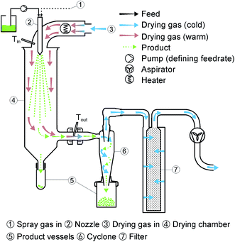
Among these attempts, the incorporation of CaO into inert solid support has attracted extensive concerns and is widely investigated, and mixing is the most common method. In our recent review,37 we summarized and divided the method into four different categories through the used precursors: (i) dry mixing of precursors; (ii) wet mixing of soluble calcium precursors and soluble support precursors; (iii) suspension mixing of insoluble calcium precursors and support precursors, and (iv) sol mixing of a soluble precursor and an insoluble precursor. The desired performances of synthetic sorbents could be generally achieved because CaO is well dispersed into inert support matrix by latter three methods (wet, suspension and sol mixings). However, these three mixing techniques all require a drying process usually in an oven or furnace. This drying-in-oven/furnace process is not practical during large-scale production. Moreover it also consumes a large amount of energy, which would exert an adverse impact on the industrialized application of CLP. We have recently proposed a spray-drying technique to substitute the conventional drying-in-oven/furnace process to synthesize CaO-based sorbents, successfully obtaining the sorbents with high cyclic CO2 capture performance.38 The technique of spray-drying, which has been commercially applied for quick drying to achieve dry powders from solution, suspension or sol, has been widely used in the food and pharmaceutical industries.39
The application of spray-drying technique on solution (wet mixing precursors) and suspension (suspension mixing precursors) has been studied in our previous study. However, sol mixing (one soluble precursor and one insoluble precursor) was the mostly used technique in the literature9,14,22,40–42 and four typical studies are summarized as follows. (i) Insoluble nano-CaCO3 and soluble Ti(OC4H9)4 were mixed in dehydrated ethanol to produce CaO incorporated in CaTiO3 matrix, achieving around 0.24 g-CO2 per g-sorbent at the 40th cycle.43 (ii) Insoluble powdered CaO and soluble Al(NO3)3·9H2O were mixed in 2-propanol and distilled water to produce CaO incorporated in Ca12Al14O33 matrix, achieving 0.39 g-CO2 per g-sorbent at the 50th cycle.22 (iii) Insoluble limestone and soluble Mg(NO3)2·6H2O were mixed in tetrahydrofuran to produce CaO incorporated in MgO matrix, achieving ∼0.30 g-CO2 per g-sorbent at the 80th cycle.14 (iv) Soluble Ca(CH3COO)2·0.4H2O and insoluble MgC2O4·2H2O were mixed in 2-propanol produce CaO incorporated in MgO matrix, achieving 0.44 g-CO2 per g-sorbent at the 126th cycle.44
Therefore it is of great significance to investigate the application of spray-drying technique to synthesize CaO-based sorbents from the mostly studied sol mixture. Herein, four typical synthetic CaO-based sorbents were produced by the spray-drying technique, using either insoluble calcium precursor or insoluble support precursor with the other one soluble. X-ray diffraction, N2 adsorption and field emission scanning electron microscope with elemental mapping are employed to investigate the reasons for the performance of the sorbents.
2. Experimental
2.1. Synthesis of sorbents
The first step for synthesis of sorbents was mixing the calcium precursor and the inert support precursor in the solvent to form a sol. The similar mixing methods were also reported in different literature.43,45,46 Four different sols were prepared according to the procedures as follows.
(i) Sol mixture from mixing nano-CaCO3 and Ti(OC4H9)4. 7.62 g of nano-CaCO3 was added into 150 mL of dehydrated CH3CH2OH to form a mixture. Then, a solution was made from 3.13 g of Ti(OC4H9)4 and 100 mL of dehydrated CH3CH2OH. Finally, the mixture was poured into the solution to form a sol followed by adding 100 mL of deionized water and continuous stirring.
(ii) Sol mixture from mixing CaO and Al(NO3)3·9H2O. 4.73 g of Al(NO3)3·9H2O was dissolved in 150 mL of deionized water to form a clear solution. 4.36 g of CaO was dispersed in 300 mL of isopropyl alcohol, which was then mixed with the solution.
(iii) Sol mixture from mixing Ca(CH3COO)2·H2O and MgAl2O4. 1.88 g of Mg(CH3COO)2·4H2O and 1.06 g of AlO(OH) were added into 500 mL of deionized water and stirred, followed by drying to form solid particles. The particles were calcined at 1000 °C for 4 h to produced spinel (MgAl2O4). The spinel and 11.79 g of Ca(CH3COO)2·H2O was mixed in 100 mL of isopropyl alcohol and 400 mL of deionized water.
(iv) Sol mixture from mixing Ca(CH3COO)2·H2O and MgO. 4.63 g of MgC2O4·2H2O was calcined at 700 °C for 2 h to produce MgO particles. Then, the particles and 11.79 g of Ca(CH3COO)2·H2O was mixed in 100 mL of isopropyl alcohol and 400 mL of deionized water.
2.2. Performance test of sorbents for CO2 capture
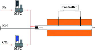
The cyclic carbonation–calcination performance of sorbents was tested in a fixed-bed quartz reactor with two heating zones, as shown in Fig. 2. Each heating zone was temperature-controlled separately. In order to investigate the effect of calcination atmosphere on the performance of sorbents, each sorbent was tested under two different calcination atmospheres: 100% N2 and 70% CO2/30% N2.The carbonation conversion (Xn) of CaO in sorbents and the capture capacity (C) of sorbents were calculated using the following equations.
 | (1) |
 | (2) |
2.3. Sample characterization
The morphology and elemental composition of the sorbents were analyzed using a field emission scanning electron microscope (FE-SEM, Sirion 200, FEI). A Micromeritics ASAP 2020 was used to determine the BET surface of the sorbents. The crystalline composition of the sorbents was analyzed by X-ray diffraction (XRD, X'Pert PRO, PANalytical B. V.). The grain size of CaO in sorbents can be obtained from the XRD diffraction patterns, which can be determined by the Scherrer equation:
 | (3) |
3. Results and discussion
The synthesis process and FSEM-EDS mapping of synthesis sorbent are illustrated in Fig. 3. As denoted in the mapping, CaO particles are homogeneously dispersed in the inert solid support for the synthetic sorbents produced by the spray drying method. Thus, the inert solid support can fully function as a metal framework to separate sorbent particles from each other, hence resisting the aggregation and sintering of CaO/CaCO3 grains. Therefore, it is proved that the technique of spray drying for sol mixture is an appropriate way to produce well-dispersed synthetic CaO-based sorbents.3.1. XRD analysis of sorbents
Fig. 4 shows the XRD patterns of the four fresh sorbents as well as sorbents after cyclic reactions of carbonation–calcination under different calcination atmospheres. Theoretically, Ca(OH)2 should not be existing in the final synthetic sorbents, because the calcination temperature (900 °C) in the muffle furnace is high enough to decompose Ca(OH)2, even if some amounts of Ca(OH)2 formed during the synthetic process. However, it is found that Ca(OH)2 is still present in some sorbents, such as NC-TT (Fig. 4a) and CA-MO (Fig. 4d). This is due to the quick capture of moisture in the atmosphere during sample characterization, which has also been found in the literature.47 As shown in Fig. 4a, the peaks of CaO and the CaTiO3 are observed in the diffraction spectrum of the NC-TT sorbent. CaTiO3 could be generated at 750 °C via the reaction between CaO and TiO2 derived from the raw material nano-CaCO3 and Ti(OC4H9)4.43 | ||
| Fig. 4 XRD patterns of fresh sorbents and sorbents after 13 cycles under different calcination atmospheres. | ||
For the sorbent CO-AN, a new material Ca12Al14O33 formed in addition to CaO, which is proved by the corresponding peak in Fig. 4b. The inert support Ca12Al14O33 was obtained from the reaction of CaO with Al2O3 during high temperature calcination. It was reported that Ca12Al14O33 was one of the intermediate phases while the mixture of CaCO3 (or CaO) and Al2O3 (or Al(OH)3) was heated.48–50 Li et al.22 reported that the formation of Ca12Al14O33 was associated with the calcination temperature during preparation of sorbents. Ca12Al14O33 was the only intermediate phase when the calcination temperature was between 800 °C and 1000 °C. Nevertheless, another intermediate phase Ca3Al2O6 formed in addition to Ca12Al14O33 beyond 1000 °C and Ca12Al14O33 even disappeared completely at 1200 °C and 1300 °C, leaving only Ca3Al2O6 as the intermediate.
Fig. 4c and d reveals the XRD results of the sorbents CA-SP and CA-MO. MgAl2O4 and MgO are in the presence of the XRD patterns and they do not react with CaO. Moreover, almost no changes are observed in the crystalline composition for all the four sorbents before and after cycles under different calcination atmosphere, indicating that the inert support materials also do not react with CaO during the cyclic tests.
3.2. Performance of sorbents under a N2 calcination atmosphere
Sorbents with the same CaO content (75 wt%) were tested under identical conditions and the results are provided in Fig. 5. All the synthetic sorbents show higher conversion than the calcined limestone, which proves the sintering-resistant ability of CaO obtained by adding inert support materials. Similar trends are also observed for the sorbents in terms of capture capacity except CA-SP, which is probably due to the larger CaO grain size (Fig. 7) and smaller initial specific surface area (Table 1) than those of calcined limestone. The conversions for the sorbents after the first carbonation are ranked in the following order: CA-MO > CO-AN ∼ CA-SP > NC-TT. Whereas the sequence of the conversion after the thirteenth carbonation is as follows: CO-AN > CA-MO > NC-TT > CA-SP.| Sorbent | Fresh sorbent and sorbent after cycles under different calcination atmosphere | ||
|---|---|---|---|
| Fresh | 100% N2 | 70% CO2/30% N2 | |
| NC-TT | 11.63 | 6.96 | 6.29 |
| CO-AN | 9.91 | 8.17 | 7.44 |
| CA-SP | 8.24 | 6.62 | 4.88 |
| CA-MO | 18.79 | 13.45 | 7.73 |
| Limestone | 8.35 | 5.41 | 1.26 |
As shown in Fig. 5a, the conversion of NC-TT within 13 cycles is higher than that of calcined limestone. In addition, higher capture capacity is obtained in spite of lower value in the first two cycles, which is ascribed to the lower initial CaO content than calcined limestone (Fig. 5b). It is believed that the improved performance of NC-TT was owing to the thermal stability of CaTiO3 (melting temperature 2200 K). During the preparation of NC-TT, the nano-sized CaO was coated by the product layer of CaTiO3 in a nano scale, which was formed after hydrolysis and calcination.43 Therefore, the sintering-resistant ability is increased and the sintering of the sorbent is hence retarded. This can be confirmed from two aspects. Firstly, as can be seen from the SEM images in Fig. 6a and b, there is little change of morphology after cycles. Secondly, the mean grain size of CaO in the sorbent is hardly changed (around 80 nm) after cycles (Fig. 7).
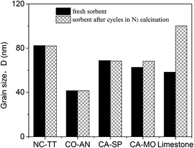 | ||
| Fig. 7 Grain size of CaO in different fresh sorbents and sorbents after 13 cycles under a N2 calcination atmosphere. | ||
CO-AN presented the best performance among the four synthetic sorbents, as shown in Fig. 5. The conversion and capture capacity decrease slowly from 79% and 0.47 g-CO2 per g-sorbent to 61% and 0.36 g-CO2 per g-sorbent. The stability of the sorbent is believed to be related to the role of Ca12Al14O33 in the sorbent. The uniform distribution of Ca12Al14O33 in the sorbent can separate the fine CaO particles from each in order to keep the particles from agglomeration, so that quick sintering of CaO could be avoided.46 SEM images in Fig. 6c and d prove that no serious sintering occurs and the porous structure still exists in the sorbent after cycles. On the other hand, it is also found from Fig. 7 that there is no obvious difference in the grain size of CaO between the fresh sorbent and the sorbent after cycles, which also supports the sintering-resistant effect benefited from using the inert material Ca12Al14O33.
For CA-SP, the MgAl2O4 dispersing in the sorbent can stop the CaO particles from quick agglomeration, which can be proved by the almost unchanged grain size of CaO in the sorbent after 13 cycles (Fig. 6). Additionally, SEM images (Fig. 6e and f) reveal the weakened sintering of the sorbent due to the remarkable thermal stability of MgAl2O4. Consequently, CA-SP shows a higher conversion than calcined limestone (Fig. 5). However, the performance of CA-SP in this study is not as stable as that reported by Li et al.,45 which is possibly associated with the particle size of MgAl2O4. The MgAl2O4 particles in their work were rod-shaped with an average diameter of 20 nm and a length of 10 nm. The particle size of MgAl2O4 in this study is larger than that. Hence, the CaO particles would not be well separated by MgAl2O4.
It is shown that CA-MO exhibits an excellent performance (Fig. 5). The initial conversion and capture capacity are the highest among the four synthetic sorbents, which are up to 83% and 0.56 g-CO2 per g-sorbent. Small MgO particles were obtained from decomposition of reagent grade MgC2O4·2H2O during high temperature calcination.51 These particles effectively prevent CaO particles from sintering severely and agglomerating too fast, as evidenced by the results from SEM analysis (Fig. 6g and h) and calculation of grain size (Fig. 7).
In comparison to the synthetic sorbents, the calcined limestone exhibited worse cyclic conversions, which can be also reflected in the micromorphology changes (Fig. 6j and k) and the grain size changes (Fig. 7). Serious sintering was observed for the calcined limestone from the SEM images and a sharp increase of CaO grain size was also found in Fig. 7.
Obviously, the capture capacity decreases with increasing cycles for all sorbents when calcined in a N2 atmosphere, although the sintering of the synthetic sorbents is not serious. The sintering can be further reflected in the reduction of the specific surface area (Table 1) and almost unchanged grain size for the synthetic sorbents (Fig. 7), which are in good accordance with the lattice diffusion mechanism proposed by German and Munir.52 This further proves that lattice diffusion can easily lead to densification of the grain rather than the grain growth, thus resulting in the decay of the capture capacity for the synthetic sorbents.
3.3. Performance of sorbents under a CO2-rich calcination atmosphere
Fig. 8 provides the performance of sorbents under a 70% CO2/30% N2 calcination atmosphere. The four synthetic sorbents still reveal higher conversion and capture capacity than calcined limestone, which means that the sintering of CaO was minished by using all the different inert materials. The conversions for the sorbents after the first carbonation can be ranked in the following order: CO-AN > CA-MO > CA-SP ∼ NC-TT. Whereas the sequence of the conversions after the thirteenth carbonation is as follows: CA-MO > CA-SP > CO-AN > NC-TT.Nevertheless, the cyclic performance is obviously worse for sorbents under a CO2-rich calcination atmosphere than that under N2 calcination atmosphere, especially for the sorbents CO-AN and CA-MO. For CO-AN, the conversion and capture capacity are merely 28% and 0.17 g-CO2 per g-sorbent after cycles, which are far lower than those (61% and 0.36 g-CO2 per g-sorbent) under N2 calcination atmosphere. For CA-MO, the conversion and capture capacity are 39% and 0.23 g-CO2 per g-sorbent after cycles, which are also lower than the values (56% and 0.33 g-CO2 per g-sorbent) under N2 calcination atmosphere. The performance of NC-TT and CA-SP decreases to some extent as well. Other researchers also reported the faster degradation of performance for sorbents under the CO2 calcination atmosphere.53 The last-cycle capacity of the synthetic sorbents (tested with the presence of CO2 during calcination stage) here and in the literature were summarized in Fig. 9. The criteria of the selection was in accordance with that used in our previous work.15,23,31 Although the synthetic sorbents in this work is not superior to some of reported sorbents, the use of spraying drying technique could still be a promising method considering its rapid fabrication of sorbents and the saved energy.
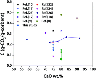 | ||
| Fig. 9 The last-cycle capacity of the synthetic sorbents here and in the literature (tested with the presence of CO2 during calcination process). | ||
The decay of the performance is generally considered to be caused by sintering of the sorbents, which was also verified from the SEM images before and after cyclic cycles (Fig. 10). The enhanced sintering under a CO2-rich calcination atmosphere has been reported to be linked with the prolonged time for CaCO3 to decompose to CaO due to the presence of high concentration of CO2 in the calcination atmosphere.53 The longer time for CaCO3 exposed to the high calcination temperature (900 °C) causes the much more serious sintering for the sorbents tested under CO2-rich atmosphere for the reasons that the Tammann temperature of CaCO3 (533 °C) is much lower than that of CaO (1313 °C). The severer sintering can be reflected by the heavier reduction of specific surface area as proved by the results in Table 1. Moreover, the severer sintering aggravates the aggregation of sorbent grains, which gives rise to the grain growth. This can be supported by the larger grain size of CaO in the synthetic sorbents after calcination in a CO2-rich atmosphere (Fig. 11). Besides, the larger increase of the grain size of the inert materials cycled under CO2-rich atmosphere compared to that under N2 atmosphere was also found (see Table 2), which deteriorated the degree of dispersion for CaO and inert materials and, thus, the anti-sintering ability. Accordingly, the performance of the sorbents deteriorated more quickly under a CO2-rich calcination atmosphere.
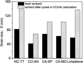 | ||
| Fig. 11 Grain size of CaO in different fresh sorbents and sorbents after cycles under a CO2-rich calcination atmosphere. | ||
| Sorbent | Inert material | Grain size of the inert material | ||
|---|---|---|---|---|
| Fresh | Calcined in 100% N2 | Calcined in 70%CO2/30% N2 | ||
| NC-TT | CaTiO3 | 82.35 | 79.55 | 83.96 |
| CO-AN | Ca12Al14O33 | 53.78 | 54.13 | 69.65 |
| CA-SP | MgAl2O4 | 37.46 | 43.12 | 49.45 |
| CA-MO | MgO | 36.75 | 34.84 | 52.37 |
4. Conclusions
Spray-drying technique, which is fast and energy-saved, is used to dry the mostly investigated sol mixture (mixing a soluble precursor and an insoluble one) to produce synthetic CaO-based sorbents for CO2 capture. Four synthetic CaO-based sorbents were prepared and it is found that CaO grains can be homogeneously dispersed in the inert solid support by this technique. To compare the performance of these sorbents, they were tested under the same conditions. The effect of CO2 in the calcination atmosphere on the capture capacity of the sorbents and associated sintering mechanisms were also examined. The following conclusions can be drawn from this study: (1) the performance of CaO was enhanced via adding inert materials under both calcination atmospheres. (2) The presence of high concentration of CO2 in the calcination atmosphere prolonged the exposure time of CaCO3 to the high calcination temperature, resulting in severer sintering for the sorbents, and the grain size of CaO became obviously larger and the specific surface area were reduced.Acknowledgements
The financial supports from National Natural Science Foundation of China (51306063) and PhD Program Foundation of the Ministry of Education of China (20130142120047) are sincerely acknowledged. The authors also wish to thank Prof. Yucheng Wang and Dr Hang Ping in Wuhan University of Technology for the guidance of the spray dryer. We are also grateful for the support from the Foundation of State Key Laboratory of Coal Combustion (FSKLCCB1602) and the Analytical and Testing Center at Huazhong University of Science and Technology.References
- S. D. Kenarsari, D. Yang, G. Jiang, S. Zhang, J. Wang, A. G. Russell, Q. Wei and M. Fan, RSC Adv., 2013, 3, 22739–22773 RSC.
- M. Broda and C. R. Muller, Fuel, 2014, 127, 94–100 CrossRef CAS.
- G. S. Grasa and J. C. Abanades, Ind. Eng. Chem. Res., 2006, 45, 8846–8851 CrossRef CAS.
- F. D. M. Daud, K. Vignesh, S. Sreekantan and A. R. Mohamed, New J. Chem., 2016, 40, 231–237 RSC.
- R. Barker, J. Appl. Chem. Biotechnol., 1973, 23, 733–742 CAS.
- Y. Li, W. Wang, X. Cheng, M. Su, X. Ma and X. Xie, Fuel, 2015, 142, 21–27 CrossRef CAS.
- J. Sun, W. Liu, Y. Hu, J. Wu, M. Li, X. Yang, W. Wang and M. Xu, Chem. Eng. J., 2016, 285, 293–303 CrossRef CAS.
- X. Zhang, Z. Li, Y. Peng, W. Su, X. Sun and J. Li, Chem. Eng. J., 2014, 243, 297–304 CrossRef CAS.
- L. Li, D. L. King, Z. Nie, X. S. Li and C. Howard, Energy Fuels, 2010, 24, 3698–3703 CrossRef CAS.
- Z.-s. Li, N.-s. Cai, Y.-y. Huang and H.-j. Han, Energy Fuels, 2005, 19, 1447–1452 CrossRef CAS.
- R. Koirala, G. K. Reddy and P. G. Smirniotis, Energy Fuels, 2012, 26, 3103–3109 CrossRef CAS.
- H. R. Radfarnia and A. Sayari, Chem. Eng. J., 2015, 262, 913–920 CrossRef CAS.
- W. Liu, B. Feng, Y. Wu, G. Wang, J. Barry and J. C. D. da Costa, Environ. Sci. Technol., 2010, 44, 3093–3097 CrossRef CAS PubMed.
- K. O. Albrecht, K. S. Wagenbach, J. A. Satrio, B. H. Shanks and T. D. Wheelock, Ind. Eng. Chem. Res., 2008, 47, 7841–7848 CrossRef CAS.
- Y. Hu, W. Liu, J. Sun, M. Li, X. Yang, Y. Zhang and M. Xu, Chem. Eng. J., 2015, 273, 333–343 CrossRef CAS.
- M. Zhao, X. Yang, T. L. Church and A. T. Harris, Environ. Sci. Technol., 2012, 46, 2976–2983 CrossRef CAS PubMed.
- H. Lu, A. Khan, S. E. Pratsinis and P. G. Smirniotis, Energy Fuels, 2009, 23, 1093–1100 CrossRef CAS.
- M. Zhao, M. Bilton, A. P. Brown, A. M. Cunliffe, E. Dvininov, V. Dupont, T. P. Comyn and S. J. Milne, Energy Fuels, 2014, 28, 1275–1283 CrossRef CAS.
- V. S. Derevschikov, A. I. Lysikov and A. G. Okunev, Ind. Eng. Chem. Res., 2011, 50, 12741–12749 CrossRef CAS.
- P. Q. Lan and S. F. Wu, Chem. Eng. Technol., 2014, 37, 580–586 CrossRef CAS.
- Y. Hu, W. Liu, W. Wang, J. Sun, X. Yang, H. Chen and M. Xu, Chem. Eng. J., 2016, 296, 412–419 CrossRef CAS.
- Z. S. Li, N. S. Cai and Y. Y. Huang, Ind. Eng. Chem. Res., 2006, 45, 1911–1917 CrossRef CAS.
- Y. Hu, W. Liu, H. Chen, Z. Zhou, W. Wang, J. Sun, X. Yang, X. Li and M. Xu, Fuel, 2016, 181, 199–206 CrossRef CAS.
- S. Stendardo, L. Andersen and C. Herce, Chem. Eng. J., 2013, 220, 383–394 CrossRef CAS.
- C. Luo, Y. Zheng, J. Yin, C. Qin, N. Ding, C. Zheng and B. Feng, Energy Fuels, 2013, 27, 4824–4831 CrossRef CAS.
- H. R. Radfarnia and M. C. Iliuta, Chem. Eng. J., 2013, 232, 280–289 CrossRef CAS.
- W. Liu, N. W. Low, B. Feng, G. Wang and J. C. Diniz da Costa, Environ. Sci. Technol., 2010, 44, 841–847 CrossRef CAS PubMed.
- H. Lu, E. P. Reddy and P. G. Smirniotis, Ind. Eng. Chem. Res., 2006, 45, 3944–3949 CrossRef CAS.
- Y. Li, C. Zhao, H. Chen, C. Liang, L. Duan and W. Zhou, Fuel, 2009, 88, 697–704 CrossRef CAS.
- F. N. Ridha, V. Manovic, A. Macchi, M. A. Anthony and E. J. Anthony, Fuel Process. Technol., 2013, 116, 284–291 CrossRef CAS.
- Y. Hu, W. Liu, J. Sun, M. Li, X. Yang, Y. Zhang, X. Liu and M. Xu, Fuel, 2016, 167, 17–24 CrossRef CAS.
- V. Manovic, D. Lu and E. J. Anthony, Fuel, 2008, 87, 3344–3352 CrossRef CAS.
- F. Zeman, Int. J. Greenhouse Gas Control, 2008, 2, 203–209 CrossRef CAS.
- B. V. Materić, C. Sheppard and S. I. Smedley, Environ. Sci. Technol., 2010, 44, 9496–9501 CrossRef PubMed.
- J. Yin, C. Zhang, C. Qin, W. Liu, H. An, G. Chen and B. Feng, Chem. Eng. J., 2012, 198, 38–44 CrossRef.
- J. Blamey, V. Manovic, E. J. Anthony, D. R. Dugwell and P. S. Fennell, Fuel, 2015, 150, 269–277 CrossRef CAS.
- W. Liu, H. An, C. Qin, J. Yin, G. Wang, B. Feng and M. Xu, Energy Fuels, 2012, 26, 2751–2767 CrossRef CAS.
- W. Liu, J. Yin, C. Qin, B. Feng and M. Xu, Environ. Sci. Technol., 2012, 46, 11267–11272 CrossRef CAS PubMed.
- A. M. Goula and K. G. Adamopoulos, Innovative Food Sci. Emerging Technol., 2010, 11, 342–351 CrossRef CAS.
- S. F. Wu and Y. Q. Zhu, Ind. Eng. Chem. Res., 2010, 49, 2701–2706 CrossRef CAS.
- N. Florin and P. Fennell, Energy Procedia, 2011, 4, 830–838 CrossRef CAS.
- C. Luo, Y. Zheng, N. Ding and C. Zheng, Korean J. Chem. Eng., 2011, 28, 1042–1046 CrossRef CAS.
- S. Wu and Y. Zhu, Ind. Eng. Chem. Res., 2010, 49, 2701–2706 CrossRef CAS.
- L. Y. Li, D. L. King, Z. M. Nie and C. Howard, Ind. Eng. Chem. Res., 2009, 48, 10604–10613 CrossRef CAS.
- L. Li, D. L. King, Z. Nie, X. S. Li and C. Howard, Energy Fuels, 2010, 24, 3698–3703 CrossRef CAS.
- Z. S. Li, N. S. Cai, Y. Y. Huang and H. J. Han, Energy Fuels, 2005, 19, 1447–1452 CrossRef CAS.
- W. Liu, B. Feng, Y. Wu, G. Wang, J. Barry and J. o. C. Diniz da Costa, Environ. Sci. Technol., 2010, 44, 3093–3097 CrossRef CAS PubMed.
- V. K. Singh, M. M. Ali and U. K. Mandal, J. Am. Ceram. Soc., 1990, 73, 872–876 CrossRef CAS.
- J. Williamson and F. P. Glasser, J. Appl. Chem., 1962, 12, 535–538 CrossRef CAS.
- B. M. Mohamed and J. H. Sharp, Thermochim. Acta, 2002, 388, 105–114 CrossRef CAS.
- L. Li, D. L. King, Z. Nie and C. Howard, Ind. Eng. Chem. Res., 2009, 48, 10604–10613 CrossRef CAS.
- R. German and Z. Munir, J. Am. Ceram. Soc., 1976, 59, 379–383 CrossRef CAS.
- C. Chen, C. Zhao, C. Liang and K. Pang, Fuel Process. Technol., 2007, 88, 171–178 CrossRef CAS.
| This journal is © The Royal Society of Chemistry 2016 |

