Fabrication of water-stable silk fibroin scaffolds through self-assembly of proteins
Danyu Yaoa,
Haifeng Liu*a and
Yubo Fan*ab
aKey Laboratory for Biomechanics and Mechanobiology of Ministry of Education, School of Biological Science and Medical Engineering, Beihang University, Xue Yuan Road No. 37, Haidian District, Beijing 100191, People’s Republic of China. E-mail: haifengliu@buaa.edu.cn; yubofan@buaa.edu.cn; Fax: +86-10-82338456; Fax: +86-10-82339428; Tel: +86-10-82338456 Tel: +86-10-82339428
bNational Research Center for Rehabilitation Technical Aids, Beijing 100176, People’s Republic of China
First published on 15th June 2016
Abstract
Silk fibroin (SF) is a promising biomaterial and has been widely used in tissue engineering. However, most of the currently used fabrication techniques require the use of organic solvents that cannot be removed thoroughly. The residual organic solvents reduce the proliferation capacity of cells. In this study, we developed water-insoluble SF scaffolds by a simple temperature induced method without the addition of organic or inorganic substances. Temperature was used to tune the self-assembly of SF during the freezing process, which resulted in water stable porous scaffolds directly. Compared with the traditional methanol treated scaffolds, the current scaffolds presented a less crystalline structure, lower elasticity modulus and faster degradation rate. In addition, human umbilical vein endothelial cells (HUVECs) showed an enhanced adhesion capacity, better spreading morphology and a faster proliferation rate on the scaffold. Investigation of the scaffold formation mechanism revealed that the performance of the current scaffold was dominated by the storage time and temperature, which tuned the self-assembly process of SF by controlling the molecular activity and contributed to the low crystallinity of the structure and water-insolubility. The results indicated that this low crystallinity scaffold holds great promise as a candidate for soft tissue repair materials.
1. Introduction
Silk-based biomaterials have been used as matrices for tissue engineering of bone, cartilage, ligaments, heart, blood vessels, nerves, skin et al. due to their perfect biocompatibility, controllable biodegradability and excellent mechanical properties.1–7 To meet the needs of tissue regeneration, various forms of silk fibroin (SF) biomaterials have been developed. Currently used fabrication techniques such as lyophilization and electrospinning require the use of organic solvents to induce a water stable structure. However, organic solvents cannot be removed thoroughly, which may reduce the cell proliferation ability.8,9 Many attempts have been made to fabricate an organic solvent-free porous scaffold for tissue engineering, using methods such as salt leaching or water annealing. The salt-leaching method uses salt particles as porogens, which avoids the use of organic solvents but leads to the need for removal of salt residue. Besides, the salt-leached scaffolds with a high β-sheet content are stiff and fragile and are not suitable for soft tissue regeneration.10 Water annealing treatments could achieve a water insoluble structure without the use of methanol. However, this process partly sacrificed the porous structure that is crucial for tissue regeneration.11It was found that the properties of SF scaffolds were much influenced by their secondary structure, which could be controlled by the self-assembly of SF.10–12 Molecular mobility, charge, hydrophilic interactions and the concentration of SF were considered as the key factors for adjusting the self-assembly process.12 In a recent study, Han et al. fabricated organic-free water-insoluble SF scaffolds by changing the SF hydrophilic interactions, which adjusted the SF self-assembly process and decided the secondary structure of the SF scaffolds.13 These scaffolds showed excellent water-stable properties and had great potential to be used in tissue regeneration.13,14 However, the SF solution needed to be pretreated for a long time. Fresh SF solution must be concentrated to about 20 wt% before being diluted and incubated to induce SF nanofiber formation. In addition, other reagents, such as acids or glycerinum were also needed to adjust the hydrophilic interactions. Therefore, it is necessary to develop a convenient technology to construct organic-free SF scaffolds.
As we all know, the SF concentration is an important factor in controlling micelle aggregation.15 SF tended to assemble into fibrils and finally formed a water insoluble hydrogel in the concentrated SF solution. The fibroin in the frozen SF solution can be considered as being in a concentrated state as well. Although the low temperature that freezes the SF solution endows SF with low molecular activity, which hinders the SF conformation changes, it remains unknown whether such frozen concentrated SF has the ability to self-assemble into a water stable structure. In this study, we developed a simple approach to achieve water insolubility by regulating the molecular activity of frozen concentrated SF. The SF solution was kept frozen to maintain the concentrated state, and the molecular activity was controlled by adjusting the storage temperature. By regulating these two factors, water stable SF porous scaffolds were fabricated directly without any pre-/post-treatment. This approach provided a green and convenient way to fabricate soft tissue regeneration materials.
2. Materials and methods
2.1 Preparation of SF solutions
Bombyx mori fibroin solutions were prepared according to previously published procedures.11 Natural silk was boiled for 30 min in an aqueous solution of 0.02 M Na2CO3 and rinsed thoroughly with deionized water to extract the sericin proteins. The process was repeated five times. Then, the sericin-free silk was dried in an oven. The extracted SF was dissolved in 9.3 M LiBr solution at 60 °C for 4 h, yielding a 20% (w/v) solution. After dialyzing against distilled water using Slide-a-Lyzer dialysis cassettes (Pierce, molecular weight cutoff 3500) for 72 h to remove the salt, the solution was centrifuged at 9000 rpm for 20 min and 4 °C to remove aggregates formed during the process. The final concentration of aqueous SF solution was about 5 wt%, determined by weighing the remaining solid after drying.2.2 Preparation of SF scaffolds
SF porous scaffolds were prepared according to a modified lyophilization method. The SF solution was poured into a cylindrically shaped container, and frozen at −20 °C for 2 h. And then, the frozen samples were moved into a −4 °C refrigerator and kept over 48 h to accomplish the structure change. Finally, the scaffolds (−20/−4-SF) were freeze-dried for subsequent characterization. SF scaffolds processed via the traditional lyophilization method and then stabilized with methanol treatment were also prepared. SF solution was frozen and kept for 50 h at −20 °C. After being freeze-dried, samples before and after methanol treatment were termed Control-SF and MA-SF, respectively.2.3 Water solubility
SF solutions were frozen at different temperatures (−4 °C, −10 °C, −20 °C, −70 °C) and freeze-dried. The freeze-dried scaffolds were immersed in ultrapure water and kept at 37 °C for 24 h. The water was refreshed 3–4 times. The scaffolds were taken out of the water after the dissolution treatment, then dried at 60 °C in an oven and weighed. The residual mass (%) was calculated by dividing the residual weight by the initial weight. Three samples were used for each measurement.2.4 Fourier transform infrared spectroscopy (FTIR) spectroscopy
The structure of the SF scaffolds was analyzed by ATR-FTIR on a NICOLET FTIR 5700 spectrometer (Thermo Scientific, FL, U.S.A.). Slices with thicknesses of about 1 mm were cut from the scaffolds with a razor blade. For each measurement, 32 scans were recorded with a resolution of 4 cm−1, with the wave number ranging from 400 to 4000 cm−1.2.5 Scanning electron microscopy (SEM)
SEM samples were prepared by cutting the dried scaffolds with a razor blade. The cross sections were pasted on the specimen stage with a conducting resin followed by being sputtered with gold for 90 s. The morphology of the scaffolds was observed by SEM (S-4800, Hitachi, Tokyo, Japan).2.6 Mechanical properties
The compression properties of the specimens (d = 10 mm, h = 12 mm) were measured with a cross head speed of 2 mm min−1 at 25 °C using an Instron 3366 testing frame (Instron, Norwood, MA) with a 100 N capacity load cell. The mechanical properties of the scaffolds were determined in wet conditions. Scaffolds were immersed in water for 24 h. All samples were measured in triplicate.2.7 Degradation
Scaffolds were incubated at 37 °C in phosphate saline (PBS). Solutions were replenished with fresh PBS every three days. At designated time points (1, 4, 7, 14, and 24 days) the samples were taken out and rinsed with distilled water. Samples were dried in a 60 °C oven for mass balance assessment.2.8 Cell culture
A human umbilical vein endothelial cell (HUVEC) line was used to evaluate the in vitro biocompatibility of these scaffolds. HUVECs were cultured in Dulbecco’s modified Eagle medium (DMEM, high glucose, HyClone) supplemented with 10% fetal bovine serum (FBS, Invitrogen, Carlsbad, CA, USA) and 1% IU ml−1 penicillin–streptomycin (Invitrogen, Carlsbad, CA). The culture dishes were maintained at 37 °C in 5% CO2 in an atmosphere with 95% humidity. Upon reaching the required quantity, HUVECs were detached from the dishes and resuspended in DMEM after being centrifuged.2.9 Cell morphology
The scaffolds were punched into small disks (with a diameter of 8 mm and height of 2 mm) and sterilized with a 126 °C autoclave sterilizer for 20 min. Cells were detached from the dishes and seeded into the scaffolds at a density of 5 × 10⁴ cells per sample. The adhesion and spreading morphology of cells cultured on the scaffolds were examined by SEM (S-4800, Hitachi, Tokyo, Japan) and confocal microscopy (Leica TCS-SPE, Germany). After culturing for 2, 6 and 12 hours, the cell-seeded scaffolds were washed three times with sterile PBS to remove the unattached cells and steeped in 4% paraformaldehyde (Sigma-Aldrich, St Louis, MO) for 30 min and washed with PBS. The rewashed samples were permeabilized with 0.1% Triton X-100 for 30 min, and stained with DAPI and FITC labeled phalloidin (Sigma-Aldrich, St Louis, MO) for fluorescent microscopy. The other samples underwent gradient dehydration with alcohol (30%, 50%, 70%, 80%, 100%, 100%) followed by lyophilization. After being sprayed with gold particles, the samples were examined using SEM.2.10 Cell viability
The effects of the scaffolds on cell proliferation were assessed using a CCK-8 assay. Samples harvested at indicated time points (1, 4 and 7 days) were transferred into a new 24-well plate. The cells were treated with 10% CCK-8 in DMEM media for 2 h at 37 °C. The absorbance at 450 nm was measured using a microplate reader. Cell number was correlated to OD. All samples were run in triplicate.3. Results and discussion
3.1 Water solubility and structure analysis
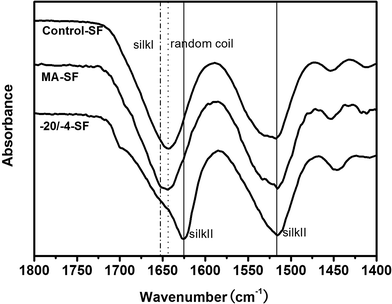
The insolubility of the SF scaffolds was determined by the weight loss of the scaffolds in water. After immersion in water and incubation for 24 h, scaffolds resulting from different freezing temperatures showed significant differences in their weight loss. Although all other groups lost over 90% of their original weight (−10 °C, 9.26 ± 2.53%; −20 °C, 7.27 ± 5.12%; −70 °C, 7.66 ± 1.74%), the −4 °C frozen group maintained 97.98 ± 0.08% of its initial weight which was similar to the methanol treated samples (98.17 ± 0.02%). It was obvious that SF of the −10 °C, −20 °C and −70 °C groups retained its water-soluble structure; however, a water insoluble structure had been formed in the −4 °C frozen samples. These results indicate the significant influence of the storage temperature on the properties of SF scaffolds. The high temperatures endowed SF molecules with enough activity to generate more stable secondary structures.ATR-FTIR was used to determine the structural changes of these scaffolds. As shown in Fig. 1, SF showed a random coil structure in the control group and turned into silk II after treatment with methanol, which was consistent with previous studies.16 A new band appeared at 1653 cm−1, indicating the formation of a silk I structure in the −4 °C frozen samples. Deconvolution of the infrared spectral region in the amide I (1595–1705 cm−1) region was performed by Peakfit software to assess the content of the different secondary structures (Table 1). Generally, the secondary structures of SF were composed of β-sheet, random coil, α-helix and turn/bend structures, among which α-helices and turns/bends are the intermediate states before silk II formation.17 When SF was frozen at lower temperatures, the scaffolds were soluble in water. SF in these scaffolds remained in an amorphous state and the content of random coils was 41.36 ± 2.44% (Table 1). After treatment with methanol, the content of both random coils (41.36 ± 2.44% to 22.71 ± 0.93%) and intermediate states (turns and α-helices) decreased, while the content of the β-sheet structure increased from 23.74 ± 0.99% to 51.30 ± 0.96%. Such changes of structure lead to the water-insoluble property of scaffolds. Interestingly, although the −20/−4-SF scaffold was water insoluble, its β-sheet content was only 31.31 ± 0.17%. Furthermore, compared with the control group, the content of random coil structure decreased from 41.36 ± 2.44% to 38.11 ± 0.54%, however, there were no significant differences between them. Thus, the increased β-sheet structure may be transformed from the intermediate states.
| Secondary structure content (%) | |||||
|---|---|---|---|---|---|
| Side chains, 1605–1615 cm−1 | Silk II, β-sheet, 1616–1637 cm−1, 1697–1703 cm−1 | Random coil, 1638–1655 cm−1 | α-Helix, 1656–1662 cm−1 | Turns, 1663–1696 cm−1 | |
| a Control-SF: the scaffolds processed via the traditional lyophilization method without any treatment; MA-SF: the scaffolds processed via the traditional lyophilization method and treated with methanol; −20/−4-SF: the scaffolds prepared by freezing the SF solution at −20 °C and storing the frozen samples at −4 °C for 48 h before lyophilization. | |||||
| Control-SF | 0.14 ± 0.01 | 23.74 ± 0.99 | 41.36 ± 2.44 | 10.07 ± 2.17 | 24.68 ± 0.76 |
| MA-SF | 0.23 ± 0.09 | 51.30 ± 0.96 | 22.71 ± 0.93 | 6.85 ± 2.10 | 18.90 ± 0.23 |
| −20/−4-SF | 0.11 ± 0.02 | 31.31 ± 0.17 | 38.11 ± 0.54 | 7.40 ± 0.07 | 23.07 ± 0.36 |
Silk II is a stable state of SF. Based on thermodynamic mechanisms, SF tends to transform from the less stable random coil structure to the silk II structure. Sufficient molecular mobility is necessary to overcome the energy barrier between the two states. The difference between the −20/−4-SF scaffolds and Control-SF scaffolds was due to the process after the SF solution was frozen. The scaffolds were kept at −4 °C or −20 °C, respectively. The fibroin in the frozen SF solution could be considered as being in a highly concentrated state. They retained molecular activity and tended to assemble into a more stable structure. The higher temperature had the effect of accelerating the rate of chain folding and reducing the time for transitions from random coil to crystal structure.15 In the case of the −4 °C stored sample, SF possessed sufficient molecular activity and had enough energy to transform from its intermediate states to the β-sheet crystal structure (Fig. 2). However, the molecular activity of the −20 °C kept samples was too low to accomplish structure change. Thus, SF of the Control-SF scaffolds retained its water unstable structures.
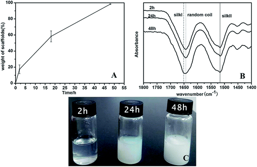
The changes from SF solution to water insoluble scaffold (−20/−4-SF) were further studied to clarify the conformation transition process of SF (Fig. 3). After the frozen samples were transferred into a −4 °C refrigerator, they were taken out at given time points (2 h, 24 h and 48 h). Half of them were thawed at room temperature and the others were lyophilized. After different times being stored in the −4 °C refrigerator, the samples showed solution (2 h), hydrogel (24 h) and porous scaffold states (48 h) (Fig. 3C). These results indicated that the conformation of SF gradually changed during the freezing process when the samples were stored in the −4 °C refrigerator. The lyophilized scaffolds showed increased water insolubility with the increase of time in the −4 °C refrigerator (Fig. 3A). The results also confirmed that the secondary structure of SF changed gradually during the process as the water solubility of SF is highly related to its secondary structure.11 When the samples were stored in the −4 °C refrigerator, the SF chains had enough molecular mobility to form a more stable structure. However, because of the low temperature the transformation was very slow. Compared with the 2 h group, a new band appeared at 1651 cm−1, indicating the formation of the silk I structure in the 48 h samples (Fig. 3B). Deconvolution of the infrared spectra demonstrated a statistically significant increase in silk II content (from 22.08 ± 1.35% to 25.44 ± 0.37%, 31.31 ± 0.17%) and a decrease in the intermediate states’ content (from 37.10 ± 1.59% to 36.61 ± 0.83%, 30.47 ± 0.42%) with the increase of time stored in the −4 °C refrigerator (Table 2). The content of random coils decreased slightly (40.72 ± 0.86% to 37.83 ± 1.17%, 38.11 ± 0.54%). We guessed that the increased silk II mainly transformed from the intermediate structure. The reason might be that the transformation from the intermediate states to the β-sheet crystal structure was easier than that from random coils to the intermediate states. However, the mechanism of the structure change was not quite clear in the present study. Further studies should be carried out to clarify the conformation transition processes of SF.
| Secondary structure content (%) | |||||
|---|---|---|---|---|---|
| Frozen time | Side chains, 1605–1615 cm−1 | Silk II, β-sheet, 1616–1637 cm−1, 1697–1703 cm−1 | Random coil, 1638–1655 cm−1 | α-Helix, 1656–1662 cm−1 | Turns, 1663–1696 cm−1 |
| a The frozen time refers to the time kept at −4 °C after the SF solution was frozen at −20 °C. | |||||
| 2 h | 0.11 ± 0.06 | 22.08 ± 1.35 | 40.72 ± 0.86 | 11.51 ± 1.74 | 25.58 ± 0.78 |
| 24 h | 0.11 ± 0.05 | 25.44 ± 0.37 | 37.83 ± 1.17 | 12.44 ± 0.58 | 24.18 ± 0.80 |
| 48 h | 0.11 ± 0.02 | 31.31 ± 0.17 | 38.11 ± 0.54 | 7.40 ± 0.07 | 23.07 ± 0.36 |
3.2 Morphology of SF scaffolds
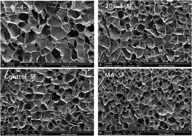
An interconnected porous system is required for nutrient delivery and cell penetration. All the SF scaffolds exhibited highly interconnected micro-porous structures (Fig. 4) with similar pore sizes before or after methanol treatment (Control-SF, 188.35 ± 18.41 μm; MA-SF, 182.62 ± 22.10 μm; −20/−4-SF, 185.52 ± 17.72 μm). Compared with the Control-SF group, the average pore size of the MA-SF scaffolds decreased slightly. When treated with methanol, the secondary structure of SF changed dramatically in a short time, indicating strenuous activity of the SF molecules, which led to the secondary structure changes as well as the slight shrinkage of the SF scaffolds. As the pores resulted from the sublimation of ice crystals formed in the SF solution, the −20/−4-SF scaffolds showed a similar pore structure with the Control-SF group. Both the −20/−4-SF scaffolds and Control-SF scaffolds were frozen at −20 °C and formed similar ice crystals that led to similar pore structures. Thus, unlike the water annealing treatment that partly sacrificed the porous structure of scaffolds, the −20/−4-SF scaffolds showed a similar morphology and porosity to the Control-SF group. The interconnected porous structure provided favorable conditions for tissue regeneration. Besides, the pore sizes could be easily regulated by freezing temperature as well. Significantly bigger pores (267.44 ± 30.23 μm) could be observed in the scaffold that was frozen at −4 °C (Fig. 4, −4/−4-SF). The results indicated that the modified lyophilization process had no adverse effect on the morphology of the SF scaffolds.3.3 Mechanical properties of scaffolds
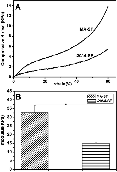
The mechanical properties of the scaffolds in wet conditions were evaluated by compressive tests (Fig. 5). The compressive modulus of the −20/−4-SF scaffolds was 14.89 ± 0.77 kPa, which was significantly (p < 0.05) lower than that of the methanol-treated scaffolds (32.65 ± 3.95 kPa). The results indicated a 54.4% decrease in the compression modulus, demonstrating the potential of the present modified lyophilization process in the fabrication of low modulus scaffolds. The difference in modulus might be due to the secondary structure of SF. Methanol treated SF scaffolds had a high β-sheet content, which resulted in the high modulus of the scaffolds. The structure change of the −20/−4-SF scaffolds was caused by the self-assembly of SF. The β-sheet content of the −20/−4-SF scaffolds was much lower than that of the MA-SF scaffolds, which led to a lower modulus. Stiffness of the scaffolds plays an important role in cell migration and differentiation. When mesenchymal stem cells (MSCs) were cultured on the matrices with different moduli, they showed significant differences in differentiation. Neurogenic markers were clearly highest on a 0.1–1 kPa substrate, while myogenic markers were highest on an 11 kPa matrix and osteogenic markers were highest on 34 kPa gels.18 In addition, Ghosh et al. found that human dermal fibroblasts migrated faster on softer substrates while proliferating preferentially on the stiffer ones.19 Thus, the scaffolds used for regeneration of different tissues should be designed based on the special requirements of each to achieve suitable mechanical properties. The present study provided a simple way to acquire low modulus scaffolds, which might be useful to regulate the stiffness of scaffolds to meet the requirements of different tissue regeneration.3.4 Dissolution
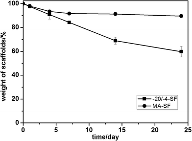
To further evaluate the differences within these scaffolds, the dissolution in PBS of the scaffolds was assessed. After 24 days of degradation, all samples kept their macroscopic shape. Both scaffolds dissolved slowly in PBS, over 80 percent of their mass remained after 7 days (Fig. 6). The MA-SF scaffolds lost 10.36 ± 1.42% of their mass after 24 days while the −20/−4-SF scaffolds lost 40.23 ± 4.36%. Statistical calculation indicated that the degradation rates of the two samples had a significant difference (p < 0.05). The −20/−4-SF scaffolds degraded more quickly than the MA-SF scaffolds. Lu et al. showed that the degradation of SF scaffolds was influenced by the secondary structure of SF.20 Compared with the higher silk II content scaffolds, scaffolds with a lower silk II content degraded more rapidly. The low β-sheet structure of the −20/−4-SF scaffolds led to their quick degradation.3.5 In vitro biocompatibility
Cell responses were assessed by HUVEC attachment, spreading and proliferation. Fig. 7 shows cell adhesion and spreading behavior on different scaffolds. The cells extended filiform pseudopodia on the cell–matrix interface and retained their sphere morphology after 2 h of seeding. Although various studies indicated that stiffer matrixes generally promote cell spreading, we found that the cells spread well on the softer −20/−4-SF scaffolds but remained spherical on the stiffer MA-SF scaffolds after 12 h of seeding (Fig. 8), indicating that the new fabrication process had positive effects on cell spreading. In addition, the cells on the −20/−4-SF scaffolds showed an enhanced adhesion ability compared to those on the traditional scaffolds. The samples were transferred into a new 24-well plate for CCK-8 assay to eliminate the influence of cells that might exist on the culture plate. According to the CCK-8 assessment, although implanted with the same amount of HUVECs, the average OD value of the −20/−4-SF scaffolds was 1.7 times higher than that of the MA-SF scaffolds after 24 h of being cultured (Fig. 9). The enhanced cell attachment and spreading capacities might be due to the non-organic solvent fabrication process of the −20/−4-SF scaffolds. Traditional scaffolds required methanol treatment to obtain a water stable structure. However, the methanol cannot be thoroughly removed, which may be harmful to cells and reduce the ability to form new tissue.8,9 On the contrary, the preparation of the −20/−4-SF scaffolds was all-aqueous and green without using any organic solvents, offering a more suitable microenvironment for cell proliferation. Besides, Jin et al. found that a SF film with a reduced β-sheet structure could support cell attachment and proliferation in an improved fashion.21 Thus, the −20/−4-SF scaffolds with a relatively low β-sheet content may be beneficial for cell attachment.4. Conclusions
SF scaffolds were prepared using an organic-free approach by varying the freezing temperature. The self-assembly of fibroin in a relatively higher storage temperature allowed the formation of silk II. This scaffold presented a lower β-sheet content, lower elasticity modulus and enhanced cell attachment abilities in comparison to the methanol treated samples. The present findings provide a way to construct SF based scaffolds with a low β-sheet content and no organic solvent residues. We anticipate that this approach will affect the fabrication of other materials especially other proteins and their ramifications as well.Acknowledgements
This work was supported by the National Key Technology R&D Program (2012BAI18B06, 2014BAI11B02, 2014BAI11B03), National Natural Science Foundation of China (31470938, 11421202, 61227902, and 11120101001), International Joint Research Center of Aerospace Biotechnology and Medical Engineering of the Ministry of Science and Technology of China, 111 Project (B13003), Research Fund for the Doctoral Program of Higher Education of China (20131102130004), The transformation project for major achievements for the Central Universities in Beijing (ZDZH20141000601), and Fundamental Research Funds for the Central Universities.References
- J. H. Ye, Y. J. Xu, J. Gao, S. G. Yan, J. Zhao, Q. Tu, J. Zhang, X. J. Duan, C. A. Sommer and G. Mostoslavsky, Biomaterials, 2011, 32, 5065–5076 CrossRef CAS PubMed.
- J. Steele, S. McCullen, A. Callanan, H. Autefage, M. Accardi, D. Dini and M. Stevens, Acta Biomater., 2014, 10, 2065–2075 CrossRef CAS PubMed.
- H. Liu, X. Li, X. Niu, G. Zhou, P. Li and Y. Fan, Biomacromolecules, 2011, 12, 2914–2924 CrossRef CAS PubMed.
- C. Patra, S. Talukdar, T. Novoyatleva, S. R. Velagala, C. Mühlfeld, B. Kundu, S. C. Kundu and F. B. Engel, Biomaterials, 2012, 33, 2673–2680 CrossRef CAS PubMed.
- H. Liu, X. Li, G. Zhou, H. Fan and Y. Fan, Biomaterials, 2011, 32, 3784–3793 CrossRef CAS PubMed.
- K. Chwalek, M. D. Tang-Schomer, F. G. Omenetto and D. L. Kaplan, Nat. Protoc., 2015, 10, 1362–1373 CrossRef CAS PubMed.
- B. Kundu, R. Rajkhowa, S. C. Kundu and X. Wang, Adv. Drug Delivery Rev., 2013, 65, 457–470 CrossRef CAS PubMed.
- X. Wang, W. Li and V. Kumar, Biomaterials, 2006, 27, 1924–1929 CrossRef CAS PubMed.
- S. S. Kim, M. S. Park, O. Jeon, C. Y. Choi and B. S. Kim, Biomaterials, 2006, 27, 1399–1409 CrossRef CAS PubMed.
- D. Yao, S. Dong, Q. Lu, X. Hu, D. L. Kaplan, B. Zhang and H. Zhu, Biomacromolecules, 2012, 13, 3723–3729 CrossRef CAS PubMed.
- Q. Lu, X. Wang, S. Lu, M. Li, D. L. Kaplan and H. Zhu, Biomaterials, 2011, 32, 1059–1067 CrossRef CAS PubMed.
- Q. Lu, H. Zhu, C. Zhang, F. Zhang, B. Zhang and D. L. Kaplan, Biomacromolecules, 2012, 13, 826–832 CrossRef CAS PubMed.
- H. Han, H. Ning, S. Liu, Q. Lu, Z. Fan, H. Lu, G. Lu and D. L. Kaplan, Adv. Funct. Mater., 2016, 26, 421–432 CrossRef CAS PubMed.
- Y. Pei, X. Liu, S. Liu, Q. Lu, J. Liu, D. L. Kaplan and H. Zhu, Acta Biomater., 2015, 13, 168–176 CrossRef CAS PubMed.
- C. Chen, C. Chuanbao, M. Xilan, T. Yin and Z. Hesun, Polymer, 2006, 47, 6322–6327 CrossRef CAS.
- X. Hu, D. Kaplan and P. Cebe, Macromolecules, 2006, 39, 6161–6170 CrossRef CAS.
- D. E. Discher, P. Janmey and Y. l. Wang, Science, 2005, 310, 1139–1143 CrossRef CAS PubMed.
- A. J. Engler, S. Sen, H. L. Sweeney and D. E. Discher, Cell, 2006, 126, 677–689 CrossRef CAS PubMed.
- K. Ghosh, Z. Pan, E. Guan, S. Ge, Y. Liu, T. Nakamura, X. D. Ren, M. Rafailovich and R. A. Clark, Biomaterials, 2007, 28, 671–679 CrossRef CAS PubMed.
- Q. Lu, X. Hu, X. Wang, J. A. Kluge, S. Lu, P. Cebe and D. L. Kaplan, Acta Biomater., 2010, 6, 1380–1387 CrossRef CAS PubMed.
- H. J. Jin, J. Park, V. Karageorgiou, U. J. Kim, R. Valluzzi, P. Cebe and D. L. Kaplan, Adv. Funct. Mater., 2005, 15, 1241–1247 CrossRef CAS.
| This journal is © The Royal Society of Chemistry 2016 |

