Liquid metal wheeled small vehicle for cargo delivery

You you Yaoa and Jing Liu*ab
aDepartment of Biomedical Engineering, Tsinghua University, Beijing 100084, PR China. E-mail: yaoyy14@mails.tsinghua.edu.cn; jliubme@mail.tsinghua.edu.cn; Tel: +86 010 62798963
bTechnical Institute of Physics and Chemistry, Chinese Academy of Sciences, Beijing 100084, PR China

Received 25th April 2016 , Accepted 3rd June 2016

First published on 6th June 2016


Abstract

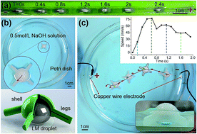
Miniaturized-vehicles are witnessing an increasing demand in many areas such as lab-on-chip, flexible fabrication, micro fluidics and small object manipulation. Lots of effort has therefore been made to build a small-scale, controllable, robust and adaptable carrying vehicle. To explore an alternative way, an innovative vehicle driven by liquid metal droplet “wheels” is presented with a geometric size in the millimeter scale. Unlike former trials, this vehicle is a movable structure composed of soft wheels and a rigid body. Such a hybrid construction adapts to multiple electrolytes especially NaOH solution. Under variable conditions of electrical voltages and channels, the present vehicle can be controlled precisely to achieve progression, steering and more complex locomotion. With a boat-like core body, the vehicle can take burdens up to 0.4 gram at a speed of about 25 mm s−1. More sophisticated vehicles with integrated manipulators and power supplies could still be built based on the current attempt. This kind of vehicle design realizes complex and accurate control as well as driving of a miniaturized robotic structure. The present finding may shed light on the construction of further complex miniaturized machines or robots in the future.


Introduction

Micro robot devices have gained significant attention over the last few decades. Vast structures and manufacturing methods have been carried out by way of the latest technologies such as MEMS, biomedical chips and molecular self-assembly, etc.1–8 Miniaturized-motors are one of the hottest research topics in the small-device area, as power supply is a key factor among them during their delivery, transport, assembly and mixing process. Previous efforts to build small scale motors generally fall into two main categories. One is catalytic-chemical reactions1,2,7 which generate gas bubbles among the surface of rod or sphere shaped motors dipping in chemical fuel solutions. The other one is to implement exterior physical fields such as electric field or magnetic field.9–13 Electric field can break up the symmetry of surface energy of motors via gas generation or uneven electric double layer, while magnetic field can exert directional mechanical forces on granular motors with magnets attached upon the surfaces or inside the bodies. Either strategy has attracted lots of attention and has been experimentally investigated so far.

Based on these motors, functional devices or carrying vehicles can be further developed. An intuitive idea is to attach target objects onto motors through electroplate or incubate techniques. Researchers in biomedical and pharmaceutical areas tend to work on this way since it can delivery drugs or modified bio-molecules with micro-scale maneuverability. In most cases, vehicles and burdens are closely integrated with no distinct interfaces, while the whole systems are powered by catalytic chemical reaction which can lead to consumption of metal electrodes. A relatively larger vessel was also devised. Diller and Sitti proposed magnetic robotic small-grippers of a customized U-shape which is manufactured by rubber molding.3 External magnetic field is needed in this particular example which can control the position, orientation and opening/closing state of grippers. In view of associating and aligning these different types of small-vehicles, we can further depict a vision of micro-factory concept.2,3 Differing from its counterpart in real industry, micro-factories have much smaller transporters, manipulators and grippers. Comprised of basic elements such as power supply, transportation, manufacture and assembly, miniaturized-factory can perform significant roles in many fields such as medicine test, cell culture, lab-on-chip and so on.

In this article we proposed a new kind of millimeter scale boat like vehicles driven by soft liquid metal wheels immersed in aqueous solutions and powered by exterior electric fields. Eutectic gallium-indium (EGaIn) liquid metal is a metal material which has a room temperature melting point and is basically composed of gallium and indium elements. Previous works have shown that liquid metal droplets can swim, swirl and deform in electrolytes based on Marangoni effect and surface tension asymmetry.14–16 Regarding liquid metal droplets as variable motors,17,18 they can be exploited as soft and compliant wheels of the miniaturized vehicles. Such assembly will accommodate the design of complex body structures as the power source can be switched from external electric field to interior button cells. In our approach, 3D printing technology is implemented to fabricate the rigid body of the vehicle. Carrying capability can be up to 0.4 gram with overall dimensions of 10 to 20 mm. Both fabrication and actuation methods can be improved in order to build vehicles of different sizes to meet varied tasks.

Experimental

Liquid metal material

Liquid metal is a variety of metal materials which have relatively low melting points ranging from 0 °C to 100 °C.19 Primary elements include gallium, indium and stannum. The most commonly used liquid metal is EGaIn eutectic alloy, while in our experiments, 76% Ga, 14% In EGaIn is particularly exploited. EGaIn has a very high surface tension and fine conductivity up to 3.46 × 10⁶ S m−1 (at 20 °C), and has a quite low vapor pressure lower than 200 Pa (1350 °C).

Miniaturized vehicle

Liquid metal vehicle is a millimeter to centimeter scale carrier with a rigid body and several soft liquid metal wheels. In previous research, it has been found that liquid metal droplet can move with exterior electric stimuli in multiple conductive liquors such as alkaline, acid and NaCl solution where the droplet submerged (Fig. 1(a)). Thus a rigid body can be assembled with soft liquid metal droplets to form a vehicle. The body can be designed and fabricated into various shapes combined with different numbers of soft wheels. In this article, three representative structures with one, three and four wheels are presented respectively. The body structure slightly floats upon the aqueous solution in order to reduce friction retardation force. Theoretically, plenty of vehicles could be driven and controlled simultaneously.
image file: c6ra10629c-f1.tif
Fig. 1 Solo wheel liquid metal vehicle. (a) Liquid metal drop rushing toward anode in an open-top channel. Red “+” represents anodic electrode while black “−” represents cathode. Successive snapshots are overlapped on the same picture. Applied voltage is 23 V. (b) A 3D-printed body shelters a liquid metal droplet and forms a solo wheel vehicle. Inner structure can be seen from the sectional view of the vehicle below. (c) Solo wheel liquid metal vehicle can travel across the Petri dish with applied voltage of 26 V. Chromatic short arrows represent the orientations of the vehicle every 0.32 s and the positions are recorded to form the trajectory. The lower half of the vehicle is submerged in 0.5 mol l−1 NaOH solution, which is shown at lower right corner and the instantaneous speeds are plotted at upper right.

Assembly of the vehicles

For solo wheel liquid metal vehicle, a droplet of liquid metal is first injected into the Petri dish, then we use the 3D-printed shell to cover the sphere droplet. Water level is at the waist of droplet in case of that the solution might drift the shell away. For four wheel and boat-like liquid metal vehicles, firstly the copper rods are sticked onto the solid body structures, which is plastic sheet or 3D-printed triangular boat-like vehicle, then we put the partial assembled structure into electrolyte and let it float upon the surface. The water level here should allow the bottom end point of copper rods to be not far away from the vessel bottom. Thus the liquid metal wheels could bridge the distance. After that, liquid metal droplets/wheels are injected at the end points of the copper rods, contacting with the rods and the whole vehicle is finally assembled.

Activation of locomotion

Two copper electrodes are implemented at the opposite sides of basic solution. The shape of electrodes may affect the locomotion, because it influences the electric field distribution. In our experiments, wire electrodes are used for solo wheel and four-wheel liquid metal vehicles, and copper sheet electrodes for boat-like liquid metal vehicle. Electrodes are connected to a constant voltage source (ZhaoXin KXN3030D) with the applied voltage ranging from 15 V to 26 V.

Fabrication of the channels

The virtual 3D model of channels is designed by software Solidworks 2013. The PMMA transparent channel is CNC machined while the channel with three grooves is SLA 3D printed. The lengths of both channels are 100 mm, and the widths are 37 mm and 25 mm, respectively. Grooves of the 3D printed channel have widths and depths of 5 mm.

Results and discussion

Solo wheel liquid metal vehicle

At the first step, to prove the feasibility of the concept, we designed a 3D printed coat covering a liquid metal droplet, which can be regarded as a solo-wheel liquid metal vehicle. The solo wheel vehicle is a hemisphere shell with four uniformly distributed legs stick out at four extreme ends of the shell. The rod legs would support the shell structure and prevent it from overturn. A mono-venthole is arranged at the top center of the hemisphere in case of hydrogen gas accumulation which may split the vehicle and liquid metal wheel. A demi-semi sectional view of the solo-wheel vehicle is illustrated at the bottom of Fig. 1(b), of which the green part represents the 3D printed shell and legs, with grey colored liquid metal droplet coated in the center. A glass Petri dish is implemented as experimental container in which liquid metal vehicle can swim in electrolyte. Meantime, an external 26 V electric potential is applied at the two opposite ends of Petri dish (anode at left side while cathode at right side in Fig. 1(c)). The diameter of dish is about 16 cm from which we can infer that the electric field intensity is ∼173.3 V m−1. Liquid metal droplet had a volume of about 0.1 ml (the same as in Fig. 1(a)). Vehicle shell structure wraps the upper parts of droplets and would synchronize with the movement of droplet by physical contact. The electrodes are the tips of two copper wires with diameters of 0.5 mm. Half of the solo-wheel vehicle is immersed in the electrolyte of 0.5 mol l−1 NaOH, which is shown at the bottom right side of Fig. 1(c).

According to previous research,14 when an external electricfield is applied onto the electrolyte, liquid metal droplet dipping in the solution can be driven by asymmetry of surface tension. On the basis of Lippmann's equation, one has

 
image file: c6ra10629c-t1.tif(1)
where, γ is the surface tension, c is the capacitance of electric double layer (EDL) per unit area, V is the potential difference across the EDL, γ0 is the maximum surface tension when potential difference is zero. Electric potential would increase the V at the cathodic pole of liquid metal droplet and decrease the V at the anodic pole at the same time. Thus the surface tension at two opposite sides would decrease and increase respectively, meanwhile a surface tension gradient would appear simultaneously. On account of Marangoni effect, the gradient would lead to a fluxion along the surface of liquid metal droplets from cathodic pole to anodic pole. Impelled by this surface flow, liquid metal droplets can move towards the anodic electrode at a speed ranging from 10 mm s−1 to 80 mm s−1, approximately. (also shown in ESI Movie S1)

Fig. 1(c) exhibits the locomotion trajectory with a fixed time interval of 0.2 s, from which it can be noticed that the vehicle orientation would veer accordingly (orientation is labeled by red arrows along with trajectory, which is shown in the up down zoom-in view of vehicle, Fig. 1(b)). Instantaneous speed ranges from 0 to 77 mm s−1, which is spotted in upper right of Fig. 1(c). The distortion of the trajectory can be interpreted by slight unevenness of viscous friction between different legs and aqueous solution, frictional resistance between legs and Petri dish, along with irregular glass bottom. The shape of the trajectory varies within repeated experiments.

Four wheel liquid metal vehicle

Considering that solo wheel liquid metal vehicle cannot veer and take burdens, a four-wheel liquid metal vehicle is further presented, which was composed of four EGaIn droplets and a square plastic sheet. Four copper rods are adhered onto the square plastic sheet (15 mm × 30 mm) at four extremities with cyanoacrylates super glue (502 instant adhesive). The rods are curved into L-shaped structures with upper parts parallel to plastic sheet to facilitate fixation and stickup. Due to surface tension of aqueous solution and hydrophobic property of polyethylene plastic, the plastic sheet would float upon the electrolyte surface along with four L-shaped copper rods. Four EGaIn liquid metal droplets are adhered to lower parts of copper rods through wetting mechanism while the volume of each droplet is about 0.1 ml. The whole apparatus is accommodated in a polymethyl methacrylate (PMMA) open top channel and submerged in aqueous solution. The channel is a square ditch, of which the length is 100 mm, the width is 25 mm and the depth is 8 mm. On account of buoyancy generated by aqueous solution surface tension, the end points of copper rods have a distance of ∼2 mm away from the bottom of PMMA ditch. Therefore, liquid metal droplets can bridge the space with their sphere form by contacting the bottom of channel and the copper rods simultaneously.

When droplets attach and wet copper rods surface, after applying an exterior electric potential, aforementioned liquid metal locomotion can be delivered to the rods through a dragging force. For our liquid metal vehicle, with four rods and four liquid metal droplets, the whole structure can be uniformly propelled by such locomotion.

To investigate the critical characteristics of vehicle locomotion and propulsion, a series of comparative experiments are conducted. First incremental voltages are applied starting from 15 V to 23 V with a step of 4 volts. While the electrolyte is 0.5 mol l−1 NaOH solution and the electrodes are placed at two extreme ends of PMMA channel. Power supply is a constant voltage source which can provide a highest voltage up to 30 V. To better demonstrate the locomotive velocity and direction, a black letter Y signature is drawn at the upper surface of transparent plastic sheet.

Before applying the step voltage, non-wheel structure is gently placed on the surface of water solution with a tweezer. The structure would be floated by solution surface tension just like gerridae standing on water surface. At the edge of sheet an obtuse contact angle (θ) can be observed, as is illustrated in Fig. 2(a). When the structure is immersed in aqueous solution, a syringe is used to inject liquid metal towards four copper rods, respectively. Liquid metal would wet the surface of copper and adhered to it stably. After four times of injection, the four-wheel liquid metal vehicle would be assembled completely and capable to voyage (Fig. 2(b)).


image file: c6ra10629c-f2.tif
Fig. 2 Four-wheel liquid metal vehicle. (a) Schematic diagram of experimental set-up and ambient environment. Transparent plastic sheet floats upon the surface of basic solution. At four extremities there are four copper rods adhered to the sheet with four liquid metal droplet “wheels” attached to their feet, separately. θ represents the contact angle between plastic sheet and aqueous solution. Green V represents motion direction and red E represents electric field orientation. (b) Vehicle and open-top channel apparatus. The transparent plastic sheet is outlined by dashed lines, with a Y signature written on it to show the position and orientation of the vehicle. (c) Continuous captures of vehicle locomotion at every 0.4 s. Applied voltage is 19 V.

Fig. 2(c) demonstrated the continuous motion process of four wheel vehicle when applied with a 19 V electric potential. Center point of signature Y is utilized as the reference point to calculate horizontal displacement and velocity. There are three different forces affecting the vehicle structure,20 which are electric potential induced liquid metal propelling force, viscous friction between the structure and the basic solution, as well as friction between soft liquid metal wheels and PMMA substrate, respectively. For every single wheel, its propelling force is determined by liquid metal volume and adjacent electric field intensity. Considering that the precise size of each wheel cannot be strictly equivalent, and the electric field intensity is not uniformly distributed, the propelling forces of different wheels are thus unequal. Meantime, due to machining error, the friction between liquid metal wheel and PMMA channel bottom also varies according to the positions of contacting points. Taking above factors into account, the locomotive speeds of different wheels would be different, thus the vehicle would rotate and oscillate within open top channel. For instance, the upper two wheels have a higher speed compared with their lower counterparts, shown in Fig. 2(c). As a result, the letter Y signature yaws clockwise along with the plastic body and then becomes restricted by channel side wall. Such deflection happens occasionally and is dominated by the precise volumes of injected liquid metal wheels.

To depict the locomotive characteristics of liquid metal wheeled vehicle, displacements and instantaneous velocities are charted in Fig. 3(a and b) with applied voltages of 15 V, 19 V, 23 V, respectively. The positions and velocities are recorded every 0.08 s. From Fig. 3(a), we can see that the displacement of vehicle ascends gradually in any case. Whereas the red line (19 V) and blue line (23 V) are much closer to each other when compared to the black line (15 V). When the conducted voltage is lower than 15 V, the vehicle moves too slow to accomplish the entire distance of about 60 mm. It is obvious that the average speeds are not linearly related to voltage increases. To confirm such a dependency and eliminate the impact from stochastic factors, experiments are repeated with different voltage steps of 5 V and 3 V, respectively. The experimental process with 5 V voltage step is shown in ESI Movie S2. There exists a quite similar phenomenon that displacement increase rates of 20 V and 25 V are much closer than the counterpart rates with 15 V (Fig. 4(a and b)). When applying a smaller voltage interval of 3 V, such regularity still remains (Fig. 4(c and d)). To further elucidate the phenomenon, instantaneous velocity diagram is shown in Fig. 3(b), from which it can be clearly noticed that the speeds of 15 V and 19 V are much closer and would intersect with each other at several points.


image file: c6ra10629c-f3.tif
Fig. 3 (a) Displacements of the locomotion with different applied electrical potentials. (b) Instantaneous speeds of locomotion under different voltage conditions.

image file: c6ra10629c-f4.tif
Fig. 4 Displacements and instantaneous speeds of locomotion under different conditions. (a and b) Diagrams with the applied voltage interval 5 V. (c and d) The voltage interval is 3 V. (e and f) Diagrams of a single liquid metal droplet with no affiliated solid structure. The voltage interval is 3 V.

Displacement and instantaneous velocity diagrams with voltage intervals of 5 V and 3 V are shown in Fig. 4(b and d). As a comparative result, displacements and instantaneous speeds data of a single liquid metal droplet locomotion are also illustrated in Fig. 4(e and f), from which the volume of droplet is 0.1 ml and the voltage increment is 3 V.

Here is a tentative further explanation of the phenomenon.21,22 The relation between propelling force and locomotive velocity, as well as the fluidic resistance force, needs to be clarified. First we need to evaluate the Reynolds number of solid vehicle structure swimming in the pool, which is the ratio of liquid inertia force and viscous force. It can be calculated by expression

 
image file: c6ra10629c-t2.tif(2)
where ρ is the solution density, V is the flow velocity, D is the characteristic length and μ is the dynamic viscosity of the fluid. To simplify the computational model, the whole structure is regarded as a single plastic plate, thus the characteristic distance is 30 mm. The ρ and μ values of 0.5 mol l−1 NaOH solution are approximately 1 × 10³ kg m−3 and 1 × 10⁻³ Pa s, respectively. While the motion velocity is assigned with the lowest average speed, which is about 40 mm s−1. Then we can get that the Reynolds number of the system is about 1200.

The Reynolds number of the system is much larger than 1. Utilizing the equation image file: c6ra10629c-t3.tif, which is carried out by Rayleigh, we can notice that the fluidic resistance FD is proportional to the flow velocity square V2 (ρ is the solution density, CD is the drag coefficient and A is the reference area). This indicates that when the speed increases, the resistance would ascend much faster. In view of that the propelling force is roughly linearly proportional to the voltage, then we can reach a conclusion that the speed would raise slower as the applied voltage increases. For a single liquid metal droplet, such interpretation is still appropriate (Fig. 4(e and f)).

From the instantaneous speed data, it can be noticed that the speed value oscillates up and down along the time axis. This is mainly due to the uneven surface of channel bottom which is CNC milled and has scratches distributed among the groove bottom. It can be proven by the fact that speed diagrams have quite close oscillating pattern and period if squeezing the speed lines horizontally according to the travelled distance, which means vibration happens at fixed positions of the channel. Meanwhile, the unbalance of body structure and fluidic perturbation would also contribute to the fluctuation of instantaneous speed values.

For each liquid metal soft wheel, its propelling force varies with the distances between the wheel and the electrodes, thus a controllable steering can be achieved by placing copper electrodes at asymmetrical positions of vehicle in a free space, as shown in Fig. 5(a). The four-wheel liquid metal vehicle stays still in a large glass Petri dish; the filled solution is 0.5 mol l−1 NaOH alkaline solution while the diameter of Petri dish is 10 cm.


image file: c6ra10629c-f5.tif
Fig. 5 Steering and reversing. (a) Steering of the vehicle. θ represents the absolute angle of the vehicle while Δθ represents relative steering angle from which we can calculate the angular velocities. (b) Reverse of the vehicle. The coordinate at left shows the displacements along the arrow direction at every moment.

The orientation of vehicle is defined as the pointing direction of the lower part of character “Y”. If one wishes to turn the direction of vehicle, for example, right hand rotation, he or she can put the anodic electrode at the right side of the front part of vehicle, while the cathode at the left side of the front part of vehicle. Obviously the front part is closer to copper electrodes and therefore has a stronger electric field intensity. Accordingly, the front two wheels would display a higher rightward directional propulsion and then the whole vehicle would rotate clockwise. Apparently left hand rotation can also be achieved in a similar way via exchanging the anode and cathode. Another way to approach directional rotation is to place electrodes closer to the rear part of the liquid metal vehicle, while in this case, anode needs to be put at the right side of rear part of vehicle to turn it left, and left side of rear part to turn it right, contrarily. From Fig. 5(a), we can calculate that the entire average angular speed is ∼0.73 rad s−1.

Besides, analogizing to the real manned sedan, liquid metal vehicle can move backwardly, as is shown in Fig. 5(b). The anodic electrode is placed at the tail side of vehicle and the cathode in front of the vehicle. With a 19 V voltage implementation, the vehicle would back down with an average speed of ∼18.8 mm s−1. The displacement and speed here depends on the travelled distance along the downward coordinate (black arrow), while the distance numbers are labelled above red stripes with different shades.

With an overview of above experiments, it is feasible to achieve a more complex and comprehensive locomotion through combining all these individual manipulations. Compared with manned car in daily life, the presented liquid metal vehicle is much more flexible and compliant. For instance, the vehicle can move omni-directionally and spin around if the electrodes are appropriately placed. Besides the soft liquid metal wheels can play a role of bumper when the vehicle collides with other rigid objects, hence the solid structure of vehicle would be protected. When the vehicle runs along the edge of the Petri dish, liquid wheel would contact the glass wall and add a recoil force to the vehicle, in which, the liquid metal would act as guide pulley and driving wheel simultaneously.

Boat-like liquid metal vehicle

In most application situations, only a movable plastic sheet is not practical to achieve complicated tasks. To broaden the vehicle's ability, the body structure is redesigned utilizing stereolithographic (SLA) 3D printing technology. As our preliminary attempts, a triangular boat-like shaped body is fabricated, shown in Fig. 6(a). The rest parts of the structure are quite similar to the four-wheel liquid metal vehicle. Three thin copper rods are sticked to the 3D printed body. The length of rods is about 20 mm while the glue is 502 instant adhesive. Regarding the vehicle as a transporter of micro factory, more accurate trajectory would be needed. So we designed a channel with three parallel grooves at the bottom, which can be seen in the partial section view of Fig. 6(a and b). The channel would be filled with aqueous electrolyte meanwhile the body of the vehicle would float upon the solution surface. Liquid metal wheels are injected to the downward end point of the thin copper rods by syringe. Afterward, the liquid metal drops would wet the rods and embed into the grooves, separately. The diameters of wheels are 5 mm, the same as widths of the grooves. For the wheels are well confined in the groove tracks, the whole vehicle structure would follow a quite straight pathway (Fig. 6(b)). With a concave belly upon the body structure, it would be easier to carry loads as well as more complex modules, such as power source or manipulators.23,24
image file: c6ra10629c-f6.tif
Fig. 6 Boat-like liquid metal vehicle running on railway. (a) Experimental set-up of the boat-like liquid metal vehicle design. Yellow triangular structure represents the body which can take loads (the green cube). Wheels along with the copper rods are confined within three orbital grooves, corresponding to their positions. The vehicle floats upon the aqueous solution and moves in the direction of red arrow. (b) Continuous snapshots of liquid metal vehicle carrying another liquid metal droplet with a volume of 0.03 ml. Time interval is 0.2 s.

To demonstrate the cargo carrying capability of the vehicle and the relationship between the masses of loads and the velocities of locomotion, further experiment is conducted in which the vehicle carried different volumes of liquid metal droplet, in particular, empty, 0.03 ml and 0.05 ml EGaIn liquid metal (see ESI Movie S3). Motion processes are recorded accordingly. Displacements and instantaneous speeds are shown in Fig. 7(a and b).


image file: c6ra10629c-f7.tif
Fig. 7 (a and b) Displacements and instantaneous speeds of three-wheel liquid metal vehicle with different amounts of loads, which are empty, 0.03 ml liquid metal droplet and 0.05 ml liquid metal droplet, respectively.

Applied voltage is 15 V while the concentration of NaOH is about 0.8 mol l−1. From the diagrams, we can notice that the vehicle has a highest average velocity (∼40 mm s−1) when taking a 0.03 ml droplet cargo. After a few more repetitive experiments, it is found that the order of velocities is not consistent, which means that the effect of accidental disturbance from turbulence and friction overwhelms the influence of carried loads. If more experiments are conducted with other variables being precisely controlled, the exact relation between the mass of cargo and motion velocity could be further identified.

Anyhow it can be proven that such a boat-like structure design does own the carrying ability up to hundreds of milligrams. So long as the vehicle would not sink, more cargos can still be loaded. The size of the vehicle could be enlarged to increase its carrying capability. More complex tasks could be done if several customized vehicles cooperate with each other. Furthermore, if equipping the vehicle with grippers or manipulators, a desktop level miniaturized factory could be accomplished.

Another way to improve the vehicle is to mount the vehicle with untethered power source such as button cell, and employ chips and circuits to control the motion of wheels individually. As liquid metal wheel is affected by local electric field, putting electrodes close to wheels separately can reduce reciprocal interference and control the wheels precisely.

Conclusions

In summary, we have presented a novel small vehicle based on EGaIn liquid metal droplets. The principal idea of this work is to integrate the liquid metal droplets with a solid body, with the body floating upon aqueous solution to reduce the friction of contact. When applying an exterior electric potential to the vehicle, liquid metal wheels would be propelled by the induced unbalance of surface tension, which would further result in flow along the droplet surface. Here, physical wetting as well as van der Waals' force connect liquid metal wheels to the body. Thus when the wheels tend to move, the solid body would be dragged to move forward. The motion characteristics are affected by many factors, in which the dominant one is the applied voltage magnitude. With a higher voltage, the vehicle would move faster, though the speed is not linearly proportional to the voltage according to hydromechanics.

Such a small vehicle can be utilized in many practical fields like small-scale transporter, miniaturized valve, as well as micro factory.25,26 Since the vehicle is controlled by electric potential, which is very easy to modulate, it can have a higher control precision compared with some flagellum propelled swimmers. Another advantage of the current design is that the body structure can be arbitrarily customized so long as it can float upon liquid surface. Such flexibility can bring it more consolidated capabilities, along with its carrying capability. The propulsion force can be adjusted by increasing the number of wheels or voltage magnitude. To improve the present design, micro controllers and built-in power source can be implemented. It is expected that this work can inspire future researches in related areas to build more powerful and flexible miniaturized-robots,27,28 as well as helping to advance the fields of microfluidic systems, programmable intelligent machines and so on in the years to come.

Acknowledgements

This work is partially supported by the NSFC Grant 51376102 and Dean's Research Funding of the Chinese Academy of Sciences.

References

  1. W. Wang, W. Duan, S. Ahmed, T. E. Mallouk and A. Sen, Nano Today, 2013, 8, 531–554 CrossRef CAS.
  2. A. A. Solovev, S. Sanchez, M. Pumera, Y. F. Mei and O. G. Schmidt, Adv. Funct. Mater., 2010, 20, 2430–2435 CrossRef CAS.
  3. E. Diller and M. Sitti, Adv. Funct. Mater., 2014, 24, 4397–4404 CrossRef CAS.
  4. S. Nowag and R. Haag, Angew. Chem., Int. Ed., 2014, 53, 49–51 CrossRef CAS PubMed.
  5. J. Roche, S. Carrara, J. Sanchez, J. Lannelongue, G. Loget, L. Bouffier, P. Fischer and A. Kuhn, Sci. Rep., 2014, 4, 6705 CrossRef CAS PubMed.
  6. S. Tottori, L. Zhang, F. Qiu, K. K. Krawczyk, A. FrancoObregón and B. J. Nelson, Adv. Mater., 2012, 24, 811–816 CrossRef CAS PubMed.
  7. J. Wang, Lab Chip, 2012, 12, 1944–1950 RSC.
  8. D. Patra, S. Sengupta, W. Duan, H. Zhang, R. Pavlick and A. Sen, Nanoscale, 2013, 5, 1273–1283 RSC.
  9. E. Y. Erdem, Y. M. Chen, M. Mohebbi, J. W. Suh, G. T. Kovacs, R. B. Darling and K. F. Böhringer, J. Microelectromech. Syst., 2010, 19, 433–442 CrossRef.
  10. M. Takinoue, Y. Atsumi and K. Yoshikawa, Appl. Phys. Lett., 2010, 96, 104105 Search PubMed.
  11. C. Huang, J.-A. Lv, X. Tian, Y. Wang, Y. Yu and J. Liu, Sci. Rep., 2015, 5, 17414 CrossRef CAS PubMed.
  12. D. Kim and J.-B. Lee, J. Korean Phys. Soc., 2015, 66, 282–286 CrossRef CAS.
  13. X. Tang, S.-Y. Tang, V. Sivan, W. Zhang, A. Mitchell, K. Kalantar-zadeh and K. Khoshmanesh, Appl. Phys. Lett., 2013, 103, 174104 Search PubMed.
  14. L. Sheng, J. Zhang and J. Liu, Adv. Mater., 2014, 26, 6036–6042 CrossRef CAS PubMed.
  15. J. Zhang, Y. Yao and J. Liu, Science Bulletin, 2015, 60, 943–951 CrossRef CAS.
  16. J. Zhang, Y. Yao, L. Sheng and J. Liu, Adv. Mater., 2015, 27, 2648–2655 CrossRef CAS PubMed.
  17. L. Sheng, Z. He, Y. Yao and J. Liu, Small, 2015, 11, 5253–5261 CrossRef CAS PubMed.
  18. B. Yuan, S. Tan, Y. Zhou and J. Liu, Science Bulletin, 2015, 60, 1203–1210 CrossRef.
  19. K. Ma and J. Liu, Front. Energ. Power Eng. China, 2007, 1, 384–402 CrossRef.
  20. D. Wong, E. E. Beattie, E. B. Steager and V. Kumar, Appl. Phys. Lett., 2013, 103, 153707 Search PubMed.
  21. B. J. Williams, S. V. Anand, J. Rajagopalan and M. T. A. Saif, Nat. Commun., 2014, 5, 4081 Search PubMed.
  22. E. Lauga and T. R. Powers, Rep. Prog. Phys., 2009, 72, 096601 CrossRef.
  23. Z. Wang, G. Hang, J. Li, Y. Wang and K. Xiao, Sens. Actuators, A, 2008, 144, 354–360 CrossRef CAS.
  24. H. Philamore, J. Rossiter, A. Stinchcombe and I. Ieropoulos, Intelligent Robots and Systems (IROS), IEEE/RSJ International Conference on 2015, 2015, pp. 3888–3893 Search PubMed.
  25. V. Chan, K. Park, M. B. Collens, H. Kong, T. A. Saif and R. Bashir, Sci. Rep., 2012, 2, 857 Search PubMed.
  26. K. E. Peyer, L. Zhang and B. J. Nelson, Nanoscale, 2013, 5, 1259–1272 RSC.
  27. W. Gao, A. Pei and J. Wang, ACS Nano, 2012, 6, 8432–8438 CrossRef CAS PubMed.
  28. S. Guo, L. Shi, N. Xiao and K. Asaka, Robot. Autonom. Syst., 2012, 60, 1472–1483 CrossRef.

Footnote

Electronic supplementary information (ESI) available: More supplementary movies of the locomotion of the liquid metal vehicle. See DOI: 10.1039/c6ra10629c

This journal is © The Royal Society of Chemistry 2016
Click here to see how this site uses Cookies. View our privacy policy here.