
Thermoelectric properties of the chalcopyrite Cu1−xMxFeS2−y series (M = Mn, Co, Ni)
Robin Lefèvre a,
David Berthebaud*a,
M. Yu. Mychinkoac,
Oleg I. Lebedeva,
Takao Morib,
Franck Gascoina and
Antoine Maignana
a,
David Berthebaud*a,
M. Yu. Mychinkoac,
Oleg I. Lebedeva,
Takao Morib,
Franck Gascoina and
Antoine Maignana
aLaboratoire CRISMAT, UMR 6508 ENSICAEN/CNRS, ENSICAEN, UCBN, 6 boulevard du Maréchal Juin, 14050 Caen Cedex 4, France. E-mail: david.berthebaud@ensicaen.fr
bNational Institute for Materials Science (NIMS), International Center for Materials Nanoarchitecture (MANA), Tsukuba 305-0044, Japan
cDepartment of Chemistry, Institute of Natural Sciences, Ural Federal University, Ekaterinburg, Russia
First published on 2nd June 2016
Abstract
The natural chalcopyrite mineral CuFeS2 is a semiconductor material with potential for thermoelectric applications. This study presents the thermoelectric properties – electrical resistivity ρ, Seebeck coefficient S and thermal conductivity κ – of the substituted on the Cu site and/or sulfur deficient CuFeS2 chalcopyrite based series Cu1−xMxFeS2−y (M = Mn, Co, Ni, x ≤ 0.05 and y ≤ 0.02). All samples have been densified by spark plasma sintering, allowing proper measurements of S, ρ and κ at high temperature. All compounds show n-type semiconducting properties with large absolute values of S, from −220 to −340 μV K−1. Maximum ZT values up to 0.20 at 623 K were obtained for Cu0.97Mn0.03FeS2 and Cu0.98Co0.02FeS1.98. The veracity of Mn for Cu substitution into the structure has been confirmed by EDS analyses, coupled to electron diffraction within a transmission electron microscope. The latter study demonstrates the existence of twinned domains. The thermal conductivity reaches values as low as κ ∼ 1.2 W m−1 K−1 at 623 K. The magnetic properties of a Mn substituted sample did not show any significant modification in the magnetic behavior compared to the pristine CuFeS2 compound. The small negative magnetoresistance observed in CuFeS2 of about −2% at 5 K in 9 T is degraded in the Mn substituted sample.
1. Introduction
New thermoelectric materials, which could play a role in the conversion of waste heat into electricity, have triggered many studies in the past decades. The thermoelectric performances of a material are evaluated with the figure-of-merit ZT = S2T/ρ(κel + κlatt) where T is the absolute temperature, S the Seebeck coefficient, ρ the electrical resistivity, κel the electronic contribution to the thermal conductivity and κlat the thermal conductivity of the lattice (phonons).1,2 The CuFeS2 mineral crystallizing in the chalcopyrite structure type shows interesting thermoelectric properties.3 It belongs to a crystal structure family of compounds with general formula AMX2 (where A = Cu, Ag; M = Al, Ga, In, Fe; X = S, Se, Te). These materials have been studied for solar energy conversion and for nonlinear optical properties in the past years as their gap can be tuned by changing the nature of the M and/or X ions.4–6 More recently, members of this family of compounds demonstrated promising thermoelectric properties,7–9 especially CuFeS2 and its substituted derivatives.3,10–13 Due to its cheapness and earth-abundant element composition compared to other interesting thermoelectric materials, CuFeS2 is an attractive material. As for other compounds crystallizing in the chalcopyrite structure type, i.e. Cu1−xGaSbxTe2 or CuGa1−xInxTe2,14,15 CuFeS2 thermoelectric properties can be optimized by controlling the charge carrier concentration through cation substitutions such as in Cu1−xCoxFeS2 or Cu1−xFe1+x and/or creation of anionic vacancies CuFeS2−x;10–12 all of these strategies tending to reduce κlatt. In order to further our understanding of these effects on the electrical and thermal properties, we have tested the effect of different substituting elements at the Cu-site, as well as the combination of cation substitution and S-deficiency keeping the charge carrier constant. In the present work, we report on the synthesis, structural characterization and physical properties of the solid solutions Cu1−xMxFeS2−y with M = Co, Ni, Mn. Finally the best ZT values were achieved through different routes, corresponding to either Mn substituted sulfur stoichiometric in the case of Cu0.97Mn0.03FeS2 or Co-doped S-deficient composition corresponding to Cu0.98Co0.02FeS1.98.2. Experiment
In order to prevent oxidation of the reactants and of the products, all manipulations were performed under inert gas or vacuum (glove box or sealed containers). Powders of Cu (99.2%), Co (99.5%), Mn (99.95%), Ni (99.8%), Fe (99+%) and S (99.5%), all from Alfa Aesar, were used as received. Stoichiometric amounts of the elements were weighted and mixed in order to obtain approximatively 5 g of the desired phases. These powders were subsequently sealed in silica tubes (under primary vacuum). The obtained ampoules heated up to 1073 K in 8 h, were maintained at this temperature for 12 h, and then cooled down to room temperature in 6 h. The obtained powders were then densified by using Spark Plasma Sintering (SPS-1080 manufactured by SPS Syntex Corp). Three different temperature/pressure treatments were applied. First, using a Carbone Lorraine die, applying a pressure of 70 MPa, the temperature was raised up to 773 K in 5 min, and after a 30 min plateau cooled down to room temperature in 20 min (T1). A second type of treatment, similar to T1 but with a 5 min plateau at 773 K was also used (T2). A third type of treatment was done (T3), using a ultra-hard graphite die, applying a pressure of 100 MPa during heating and 5 min plateau stage at 773 K, following ref. 11. For the three processes, the pressure was released to 40 MPa in 5 min during the cooling stage. Process optimization details are discussed in the second part of the results and discussion sections. Densities values determined by the dimension method were found to be over 90% of the theoretical densities.The sample quality was checked by means of X-ray powder diffraction (XRD) at each step of the synthesis and densification process. After powder synthesis in closed vessels, XRD data were collected using X-Pert Pro Panalytical diffractometer using Cu Kα1/Kα2 radiations (λ = 1.540598 Å, 1.544426 Å) and equipped with a PIXCEL detector. Rietveld refinements were performed on diffraction pattern recorded after densification with a Rigaku Ultima III X-ray Diffractometer using Cu Kα1/Kα2 radiations, over the 2θ range of 25–100° in 2 hours. Transmission electron microscopy (TEM), including electron diffraction (ED), and high-resolution TEM (HRTEM) studies were performed on selected samples using a FEI Tecnai G2 30 UT microscope operated at 300 kV, having 0.17 nm-point-resolution and equipped with EDAX EDX detector. The TEM specimens were prepared by dispersing the ground samples in ethanol, and spreading the obtained solution onto a Cu holey carbon grid.
High temperature transport properties measurements were performed from room temperature up to 623 K, above this temperature, the samples were degraded. High temperature thermal diffusivity (κd) was measured by laser flash method using an ULVAC TC7000. κ was obtained following the relation κ = κd × Cp × d, with d the bulk density, and the specific heat Cp calculated by using the Dulong–Petit law. For the κd measurements, the samples were coated using a graphite spray in order to prevent reflection of the laser pulse. The electrical resistivity (ρ) and Seebeck coefficient (S) of the samples were measured with an ULVAC ZEM-2, by using the four probe method and differential method respectively on approx. 1.5 × 2 × 10 mm3 bars. The measurements were performed under vacuum (Ulvac TC7000) or partial-helium atmosphere (ZEM-2). The effect of Mn substitution on the magnetism has been studied by measuring magnetic moments within a SQUID MPMS magnetometer (Quantum design) using zero-field-cooled and field-cooled procedures (100 Oe). The isothermal magnetization loops were recorded varying the magnetic field in the range −5 T to 5 T. The magnetoresistances of CuFeS2 and Cu0.95Mn0.05FeS2 were evaluated by measuring ρ(H) curves at selected temperatures between 325 K and 5 K using the resistivity option of a 9 T physical properties measurement system (PPMS), from −9 T to 9 T.
3. Results and discussions
3.1. Composition selections
It was previously proposed that the spins could play a role on the transport properties of the antiferromagnet CuFeS2 (TN = 823 K).16 Also, there exists a structural transition close to TN from the tetragonal space group of the chalcopyrite to a cubic zinc blende structure above TN in which the Cu and Fe cations are disordered over the tetrahedral crystallographic sites.17 This situation motivated the previous study on the effect of carrier doping by cobalt substitution to optimize CuFeS2 thermoelectric properties. To complete the substitution effect of a magnetic cation for copper and taking into account that the Fe for Cu substitution was already reported in ref. 11, samples of Cu1−xMxFeS2, with M = Cr, Mn and Ni, were prepared by varying x from x = 0.00 to 0.10. For the Cr samples, it turns out that no solid solution exists since impurities were detected as soon as x = 0.02 on the XRD patterns. For Ni and Mn samples, limited M solubility corresponding to x = 0.04 and x = 0.05, respectively, were evidenced through XRD analyses. In addition, as a similar ZT value can be reach by M substitution for Cu and for CuFeS1.80 sulfur deficient phase,12 the combination of both effects was undertaken in order to try to enhance the ZT. For that purpose, two series were chosen, based on the previously studied series Cu1−xCoxFeS2 and on a Mn substituted series. In ref. 12, the S-deficiency has been studied for the range CuFeS2−y (0 < y < 0.25). However, it must be pointed out that as y values tend toward 0.25, the composition is closer to the related compound Cu9Fe9S16, ∼CuFeS1.77, rather than that of CuFeS2 composition. The Cu9Fe9S16 is found in the mooihoekite and talnakhite minerals, which polymorphs crystallize, respectively, in tetragonal![[P with combining macron]](https://www.rsc.org/images/entities/i_char_0050_0304.gif) 42m and cubic Ī43m space groups.18 Thus, from a too large amount of S vacancy the sample would no longer crystallize in the chalcopyrite structure. From powder XRD, the Cu9Fe9S16 phase along with others compounds of the Cu–Fe–S ternary such as Cu4Fe5S8 (ref. 19) are difficult to be distinguished since their main XRD peaks overlap with the chalcopyrite ones. Previous study on Cu9Fe9S16 by N. Tsujii et al.18 reported on the ambiguity of the crystallographic identification through XRD analyses and its relationship with the n-type degenerate semiconducting behavior. To avoid formation of impurities, in the case of “S2−y” series, such as Cu9Fe9S16, samples were synthesized with a limited nominal deficiency up to y = 0.02.
42m and cubic Ī43m space groups.18 Thus, from a too large amount of S vacancy the sample would no longer crystallize in the chalcopyrite structure. From powder XRD, the Cu9Fe9S16 phase along with others compounds of the Cu–Fe–S ternary such as Cu4Fe5S8 (ref. 19) are difficult to be distinguished since their main XRD peaks overlap with the chalcopyrite ones. Previous study on Cu9Fe9S16 by N. Tsujii et al.18 reported on the ambiguity of the crystallographic identification through XRD analyses and its relationship with the n-type degenerate semiconducting behavior. To avoid formation of impurities, in the case of “S2−y” series, such as Cu9Fe9S16, samples were synthesized with a limited nominal deficiency up to y = 0.02.
Compositions for the “S2−y” series were chosen in order to keep the same amount of positive charges than in the previous study of Cu1−xCoxFeS2, for x = 0.04 and x = 0.06 (ref. 10) where Cu and Co are considered to be monovalent and divalent, respectively. In the case of x = 0.04 and x = 0.06, the Co2+ for Cu+ substitution creates formally a decrease of 0.04 and 0.06 Fe3+. This decrease of the total oxidation state can be equilibrated by 0.02 and 0.03 sulfur vacancy, respectively to keep the Fe oxidation state constant. Like Co, Mn was first considered as Mn2+, as reported for the manganese doped CuInS2. In terms of charge carriers, Cu0.98Mn0.02FeS1.99 would be equivalent to Cu0.96Mn0.04FeS2.
Bulk samples with general formula Cu1−xMxFeS2−y (with M = Co, Mn and Ni, x ≤ 0.05 and y ≤ 0.02) were synthesized following the previous experimental processes.10 Room temperature XRD patterns (Fig. 1) of these samples evidence their purity. All diffraction peaks agree with the tetragonal space-group Ī42d of CuFeS2. No diffraction peak corresponding to other Cu–Fe–S phases could be detected.
 | ||
| Fig. 1 Powder diffraction patterns of Cu1−xMxFeS2−y samples obtained after solid state reaction. Bragg positions of CuFeS2 are represented as dark gray bars (S.G. Ī42d). (a) CuFeS2 (b) Cu0.96Ni0.04FeS2 (c) Cu0.96Mn0.04FeS2 (d) Cu0.95Mn0.05FeS2 (e) Cu0.97Mn0.03FeS2 (f) Cu0.98Mn0.02FeS1.99 (g) Cu0.98Co0.02FeS1.99 (h) Cu0.98Co0.02FeS1.98. | ||
3.2. Effect of duration and pressure during SPS treatment on the physical properties
In order to maximize the thermoelectric power-factor and as detailed in the experimental section, the SPS sintering is performed at 773 K. For this temperature plateau, three different combinations of time/pressure parameters (T1, T2, and T3) have been tested to study the densification process (see experimental part). The trials were performed for two compositions: Cu0.98Co0.02FeS1.98 and CuFeS2. Combining S and ρ measurements of the obtained sintered ceramics, the power-factors were calculated (Fig. 2). Similar values are obtained for the three different treatments. However, T1 allows reaching a higher density than T2 while T3 gave the same result as T1. Since the ultra hard graphite dies used in T3 are more brittle and more expensive, T1 was then chosen to sinter the samples. For these conditions, the performances of CuFeS2 dense ceramics are given in Table 1 where they are compared to those of the literature. Our sample has the lowest resistivity at 300 K, ρ300 K = 0.02 Ω cm, which is consistent with the lowest absolute values of Seebeck coefficient, |S300 K| = 320 μV K−1. | ||
| Fig. 2 Calculated thermoelectric power-factor for Cu0.98Co0.02FeS1.98 (filled blue) and CuFeS2 (empty gray). Squared, circled and triangled data points correspond to a 30 min plateau, 5 min and 5 min under 100 MPa. | ||
3.3. Effect of M substitution for Cu on the physical properties
Previous studies about Co, Zn and Fe substitutions demonstrated optimal compositions in terms of thermoelectric properties for Cu0.94Co0.06FeS2, Cu0.97Zn0.03FeS2 or Cu0.97Fe1.03S2.10,11,13 All these studies concluded that transition elements substituting copper decrease drastically ρ while having the same effect on |S|. Consequently, the resulting power factor was enhanced by at least 4 times compared to that of CuFeS2. Additionally, the disorder at the Cu site induced by the M substitutions leads to a concomitant decrease of κ, which enhances ZT. Transport properties ρ and S of the samples Cu0.96M0.04FeS2 (M = Mn, Co, Ni) are given in Fig. 3a and Fig. 3b. From Fig. 3a, at low temperature, the less the transition metal possesses electrons on its d-shell, the greater the conductivity is. This can be attributed to spin disorder scattering as it has been reported before upon substituting Mn by Zn.20 This tendency is reversed around 550 K, where the thermal activation of minority carrier occurs as it was reported in ref. 10–13. The ρ measurements confirm a metallic behavior for all samples, with x = 0.04, below a saturation temperature, Tsat. Above Tsat, ρ tends to decrease for Ni and Co compounds going through a maximum at Tsat = 592 K and 610 K respectively. Moreover, Tsat increases in the same order as ρ decreases from Ni to Co. It might be that since Mn has less d electrons, the Mn substituted compound present a higher Tsat. At room temperature, the nickel substituted sample is almost half less conductive than the manganese substituted sample, with ρ300 K = 12 mΩ cm and 8 mΩ cm, respectively. Ni and Mn substituted samples show greater |S|coefficients than Co sample, bringing it to 330 μV K−1 at 623 K for Mn, and a bit less for Ni with 300 μV K−1 at the same temperature. κ is given in Fig. 3c, where all samples but Co-doped ones present similar κ, from ∼6.7 W m−1 K−1 at room temperature to values between ∼1.8 and 2.6 W m−1 K−1 at 623 K. Ni and Mn substituted samples show equivalent κ values to non-doped CuFeS2. It is finally Cu0.96Mn0.04FeS2 that presents the best ZT achieving 0.17 at 623 K (Fig. 3d). Ni sample and CuFeS2 present similar values of ZT lower than that of Co and Mn. Considering these results, no further investigations were made for the Ni substituted series. In contrast, this conclusion brings interest in studying the effect of manganese stoichiometry on the properties. | ||
| Fig. 3 Thermoelectric properties of the Cu1−xMxFeS2 series (a) resistivity, (b) Seebeck coefficient, (c) thermal conductivity and (d) ZT figure-of-merit. Cu0.96Co0.04FeS2 results are taken from ref. 12. | ||
3.4. Effect due to the Mn substituted stoichiometry
Following the conclusions of Section 3.3, the results of the previous studies on the solid solutions Cu1−xZnxFeS2 and Cu1−xCoxFeS2, and also knowing that choosing a magnetic element could affect the magnetic properties, the Cu1−xMnxFeS2 solid solution has been more deeply investigated with the preparation of three additional samples corresponding to x = 0.03, 0.04 and 0.05. For x = 0.03 and x = 0.04, the values of ρ are similar (Fig. 4a), with ρ623 K = 18 mΩ cm, while for x = 0.05, ρ is twice higher at 623 K. The dependence of S on x and T are represented in Fig. 4b. By varying the Mn content, |Smax| at 623 K decreases as x increases, from S = −338 μV K−1 for x = 0.03 to S = −319 μV K−1 for x = 0.05, through S = −333 μV K−1 for x = 0.04. While Cu0.97Mn0.03FeS2 and Cu0.96Mn0.04FeS2 exhibit equivalent κ with values of 2.2 W m−1 K−1 at 623 K (Fig. 4c), the κ value for Cu0.95Mn0.05FeS2 is found to be much lower, reaching 1.2 W m−1 K−1 at 623 K, and even reaches 1 W m−1 K−1 at 673 K. It is worth notify that κel, calculated with the Wiedemann–Franz law, can be neglected when compared to the lattice component κlatt, with κel < 5% κlatt. Finally the highest calculated ZT value is obtained for the Cu0.97Mn0.03FeS2 sample (Fig. 4d). It reaches ZT = 0.20 at 623 K, similarly to the value reported for Cu0.94Co0.06FeS2.10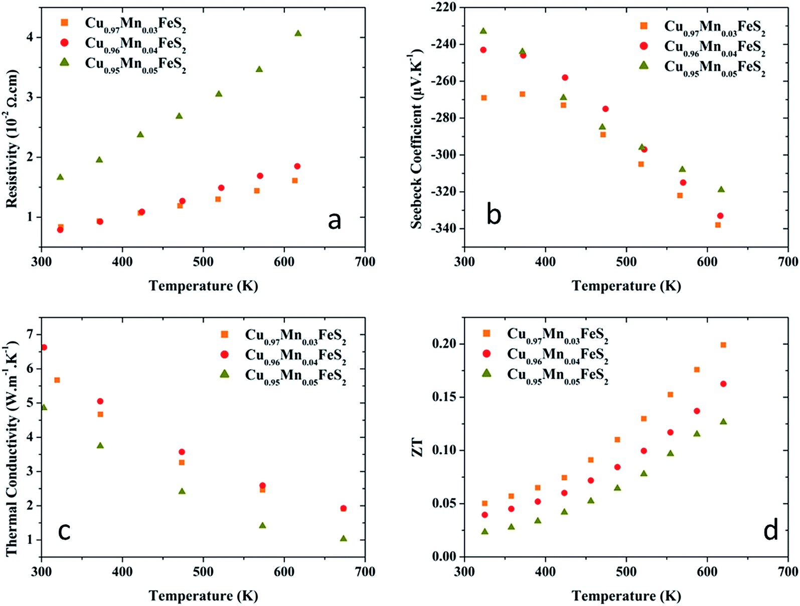 | ||
| Fig. 4 Thermoelectric properties of the Cu1−xMnxFeS2 series (a) resistivity, (b) Seebeck coefficient, (c) thermal conductivity and (d) ZT figure-of-merit. | ||
To ascertain the veracity of the Mn substitution, a transmission electronic microscopy study has been performed on the best sample of Cu0.97Mn0.03FeS2 composition. The crystallinity and possible defect structures at the nanoscale level were checked. The ED patterns taken for main zone axis [001], [100] and [110], are shown in Fig. 5a. They are indexed based on the Ī42d structure (SG 122, a = 0.53 nm, c = 1.042 nm) close to the values refined from the XRD patterns. The HRTEM image (Fig. 5b) confirms the good sample crystallinity. However, the close inspection of different crystallites of the sample by TEM revealed presence of defects – mostly twinned structure (Fig. 5c) with a {112} twin plane. For the Cu0.97Mn0.03FeS2, EDX analyzes taken from different area of one single crystallite reveal an inhomogeneous distribution of Mn within the crystallite suggesting a preferential localization of Mn. Such local disorder induced by the presence of Mn could be responsible for the lowering of κ as the Mn content increases.
 | ||
| Fig. 5 (a) ED patterns of Cu0.97Mn0.03FeS2 sample along main zone axis obtained after solid state reaction and (b) corresponding [110] HRTEM image (c) HRTEM image of twining area and corresponding ED pattern. (−112) twin planes are marked with white arrows. | ||
CuFeS2 presents an antiferromagnetic transition around 823 K,21 therefore the compound is in its antiferromagnetic state over all the T range of the ρ, S, κ measurements of the present study. Since Mn is a magnetic element, the susceptibility of the Mn substituted x = 0.03 compound was measured but only at low temperature, i.e. below TN (Fig. 6). The χ(T) curves show a difference between the zfc and fc curves which is consistent with the fact that measurements are all performed under TN. These curves are very similar to those of stoichiometric CuFeS2 sample, showing that the impact of few Mn percent on the χ is very limited. The low T (5 K) M(H) curve, showing a M maximum value of 0.03 μB per Fe mol in 5 T is also consistent with antiferromagnetism. Fig. 7 shows the dependence of the magnetoresistance of CuFeS2 and Cu0.95Mn0.05FeS2 at 5 K. At 325 K, no significant magnetoresistance is observed for both compounds. However, CuFeS2 presents a magnetoresistance reaching 2% in 9 T at 5 K. The Mn substitution lowers the magnetoresistance to a negligible value. These magnetoresistance values are much smaller than those reported for other sulfides such as Cr2S2.92 (48%) or Fe0.29Mn0.71S (−150%)21,22 and could be explained by the robust antiferromagnetic structure of CuFeS2.
 | ||
| Fig. 6 Magnetic properties of Cu0.97Mn0.03FeS2, (a) susceptibility curve with zero-field cooled and field cooled procedure, its reciprocal and the (b) magnetization curve. | ||
 | ||
| Fig. 7 Magnetoresistance as a function of magnetic field at 5 K for CuFeS2 and Cu0.95Mn0.05FeS2. (% magnetoresistance) = [(ρ(H) − ρ(0))/ρ(0)] × 100, where ρ(H) and ρ(0) are the resistivity with and without the magnetic field H, respectively. | ||
3.5. Effect of sulfur sub-stoichiometry with cobalt and manganese substituted samples
ρ and S of the samples Cu1−xMxFeS2−y are represented in the Fig. 8a and b. A higher sulfur deficiency decreases ρ, as it was reported in ref. 12. At 623 K, the resistivity of Cu0.98Co0.02FeS1.98 is half the ρ value for Cu0.98Co0.02FeS1.99, with 9 mΩ cm. The Cu0.98Mn0.02FeS1.99 ρ value is almost 6.5 times the one of Cu0.98Co0.02FeS1.98. The S values of the samples are similar for Cu0.98Mn0.02FeS1.99 and Cu0.98Co0.02FeS1.98, with values around −235 μV K−1, but Cu0.98Co0.02FeS1.99 |S| is almost 1.5 times higher at high temperature, |S623 K| = 330 μV K−1. The κ values are shown in the Fig. 8c, the sulfur deficiency does not affect the κ at high temperature, at 623 K, with values around 1.7 W m−1 K−1 as for Co doped not sulfur deficient materials, but the Mn substituted sulfur-deficient compound shows lower κ values at 623 K, below 1 W m−1 K−1. For Cu0.98Co0.02FeS1.99 and Cu0.98Co0.02FeS1.98, these values are similar to the previously established corresponding stoichiometry in terms of charge carriers (Section 3.1) Cu0.96Co0.04FeS2 and Cu0.94Co0.06FeS2, respectively. It suggests that Co is indeed 2+ charged. However, Cu0.98Mn0.02FeS1.99 which was expected to be equivalent to Cu0.96Mn0.04FeS2 would rather corresponds to a Cu0.95Mn0.05FeS2 compound or even a hypothetical Cu0.94Mn0.06FeS2. Indeed, with similar κ, the resistivity of Cu0.98Mn0.02FeS1.99 is about 60 mΩ cm at 623 K, while Cu0.95Mn0.05FeS2 only achieves 40 mΩ cm at the same temperature. It then suggests that if the Cu0.98Mn0.02FeS1.99 would be equivalent to Cu0.94Mn0.06FeS2 in terms of charge, Mn would be then 4+ charged.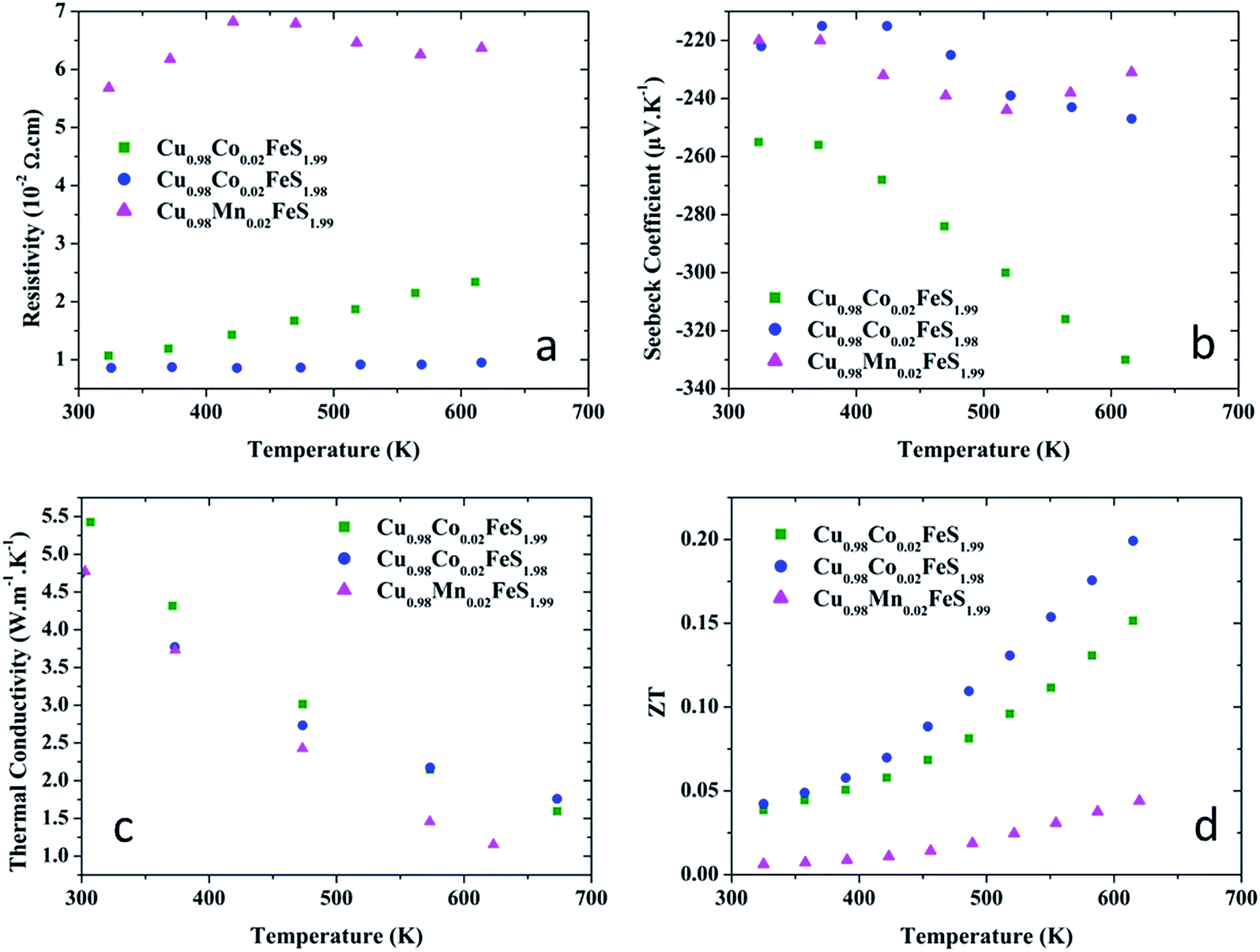 | ||
| Fig. 8 Thermoelectric properties of the Cu1−xMxFeS2−y series (a) resistivity, (b) Seebeck coefficient, (c) thermal conductivity and (d) ZT figure-of-merit. | ||
ZT are given in Fig. 8d, the highest ZT is found for Cu0.98Co0.02FeS1.98 with ZT = 0.20 at 623 K. This value is similar with the previously reported Cu0.94Co0.06FeS2. It is found at 623 K that the resistivity and the Seebeck coefficient of Cu0.98Co0.02FeS1.98 and Cu0.94Co0.06FeS2 were comparable, with |S| = 247 and 240 μV K−1 and ρ = 0.95 and 1.05 mΩ cm, respectively.
4. Conclusion
SPS process optimization and substitution/deficiency study on the Cu1−xMxFeS2−y series with M = Mn, Co, Ni; x ≤ 0.05 and y ≤ 0.02 have been successfully carried out. In these substitutions ranges, the chalcopyrite is formed without significant amount of impurities. Among the three transition metals: Co, Ni and Mn, the solid solution with Mn has been more particularly studied. TEM/ED analyzes proved the veracity of Mn substitution and the presence of twinned domains. The low thermal conductivity for a chalcopyrite induced by the increase of Mn content, down to 1 W m−1 K−1 at 673 K for Cu0.95Mn0.05FeS2. This study was performed in a goal to maximize the PF and obtain the lowest κlatt, from both cations choice and sulfur deficient samples. Of all the sulfur deficient samples, the ρ of Cu0.98Co0.02FeS1.98 was found to be the lowest one, while the manganese doped Cu0.97Mn0.03FeS2 showed the highest S values, with respective power factor values of 6 and 7 × 10⁻⁴ W m−1 K−2 at 623 K. Combining that with the respective κ values of 1.75 and 1.92 W m−1 K−1, both samples exhibit ZT values of 0.20 at 623 K. The improvements of these material properties are still being studied, and other substitutions could be performed to improve the ZT, such as Se substitution for S. Moreover, recent techniques showed that they are other possible routes for improving thermoelectrics, such as powder nanotexturation, or nano-inclusion of others phases, or even synthesizing composite based on chalcopyrite.Acknowledgements
Financial support from the LABEX EMC3 (Energy Materials and Clean Combustion Center) is gratefully acknowledged by the authors. T. Mori is supported by CREST, JST. The authors also gratefully thank G. Renouf, F. Veillon, Dr A. Ullah Khan and Dr S. Maruyama for their technical assistance.References
- D. M. Rowe, CRC Handbook of thermoelectrics, CRC, Boca Raton, 1995 Search PubMed.
- R. R. Heikes and R. W. Ure, Thermoelectricity: science and engineering, Interscience Publishers, 1961 Search PubMed.
- R. Ang, A. U. Khan, N. Tsujii, K. Takai, R. Nakamura and T. Mori, Angew. Chem., Int. Ed., 2015, 54, 12909–12913 CrossRef CAS PubMed.
- R. W. Birkmire, Sol. Energy Mater. Sol. Cells, 2001, 65, 17–28 CrossRef CAS.
- D. Xue, K. Betzler and H. Hesse, Phys. Rev. B: Condens. Matter Mater. Phys., 2000, 62, 13546–13551 CrossRef CAS.
- N. Guezmir, T. B. Nasrallah, K. Boubaker, M. Amlouk and S. Belgacem, J. Alloys Compd., 2009, 481, 543–548 CrossRef CAS.
- T. Plirdpring, K. Kurosaki, A. Kosuga, T. Day, S. Firdosy, V. Ravi, G. J. Snyder, A. Harnwunggmoung, T. Sugahara, Y. Ohishi, H. Muta and S. Yamanaka, Adv. Mater., 2012, 24, 3622–3626 CrossRef CAS PubMed.
- A. Yusufu, K. Kurosaki, A. Kosuga, T. Sugahara, Y. Ohishi, H. Muta and S. Yamanaka, Appl. Phys. Lett., 2011, 99, 061902 CrossRef.
- J. Yao, N. J. Takas, M. L. Schliefert, D. S. Paprocki, P. E. R. Blanchard, H. Gou, A. Mar, C. L. Exstrom, S. A. Darveau, P. F. P. Poudeu and J. A. Aitken, Phys. Rev. B: Condens. Matter Mater. Phys., 2011, 84, 075203 CrossRef.
- D. Berthebaud, O. I. Lebedev and A. Maignan, J. Materiomics, 2015, 1, 68–74 CrossRef.
- N. Tsujii, T. Mori and Y. Isoda, J. Electron. Mater., 2014, 43, 2371–2375 CrossRef CAS.
- J. Li, Q. Tan and J.-F. Li, J. Alloys Compd., 2013, 551, 143–149 CrossRef CAS.
- Y. Li, T. Zhang, Y. Qin, T. Day, G. J. Snyder, X. Shi and L. Chen, J. Appl. Phys., 2014, 116, 203705 CrossRef.
- J. Cui, Y. Li, Z. Du, Q. Meng and H. Zhou, J. Mater. Chem. A, 2012, 1, 677–683 RSC.
- Y. Li, Q. Meng, Y. Deng, H. Zhou, Y. Gao, Y. Li, J. Yang and J. Cui, Appl. Phys. Lett., 2012, 100, 231903 CrossRef.
- N. Tsujii and T. Mori, Appl. Phys. Express, 2013, 6, 043001 CrossRef.
- T. E. Engin, A. V. Powell and S. Hull, J. Solid State Chem., 2011, 184, 2272–2277 CrossRef CAS.
- N. Tsujii and T. Mori, in Symposium P – Mechanics of Energy Storage and Conversion—Batteries, Thermoelectrics and Fuel Cells, 2014, vol. 1680 Search PubMed.
- J. F. Rowland and S. R. Hall, Acta Crystallogr., Sect. B: Struct. Crystallogr. Cryst. Chem., 1975, 31, 2105–2112 CrossRef.
- S. R. Brown, E. S. Toberer, T. Ikeda, C. A. Cox, F. Gascoin, S. M. Kauzlarich and G. J. Snyder, Chem. Mater., 2008, 20, 3412–3419 CrossRef CAS.
- T. Teranishi, J. Phys. Soc. Jpn., 1961, 16, 1881–1887 CrossRef CAS.
- G. A. Petrakovskii, L. I. Ryabinkina, G. M. Abramova, A. D. Balaev, D. A. Balaev and A. F. Bovina, J. Exp. Theor. Phys. Lett., 2000, 72, 70–72 CrossRef CAS.
| This journal is © The Royal Society of Chemistry 2016 |