Controlling the magnetic properties of polymer–iron oxide nanoparticle composite thin films via spatial particle orientation

Jaseung Koo*a, Hyeri Kimab, Ki-Yeon Kima, Young Rae Janga, Jeong-Soo Leea, Sung Won Yoonc, Byoung Jin Suhc, Taekyung Yud, Joona Bangb, Kyunghwan Yoone, Guangcui Yuanf and Sushil K. Satijaf
aDivision of Neutron Science, Korea Atomic Energy Research Institute (KAERI), Daejeon, 305-353, Korea. E-mail: jkoo@kaeri.re.kr
bDepartment of Chemical and Biological Engineering, Korea University, Seoul, 136-713, Korea
cDepartment of Physics, Catholic University of Korea, Bucheon, 420-743, Korea
dDepartment of Chemical Engineering, Kyunghee University, Yongin, 446-701, Korea
eLG Chemical, Daejeon, 305-738, Korea
fCenter for Neutron Research, National Institute of Standards and Technology, Gaithersburg, MD 20899, USA

Received 18th April 2016 , Accepted 4th June 2016

First published on 6th June 2016


Abstract

We investigated the effect of Fe3O4 nanoparticle orientation on the magnetic properties of hybrid polymer nanocomposite thin films. A multilayer thin film consisting of alternating layers of polymers and assembled iron oxide nanoparticles was prepared by spin coating and Langmuir–Blodgett techniques. Transmission electron microscopy and neutron reflectivity measurements were employed to determine structural information related to the lateral orientation of the Fe3O4 nanoparticle monolayer and the layered architecture along the depth of the multilayer, respectively. The magnetic properties of the hybrid multilayer were characterized by SQUID magnetometry and compared with the properties of a spin-coated polymer nanocomposite thin film containing homogenously dispersed Fe3O4 nanoparticles. We found that the closely-packed monolayer structure of the Fe3O4 nanoparticles changed the magnetic properties on account of the dipolar interactions between particles, whereas the homogeneously-dispersed nanoparticles embedded in the polymer matrix exhibited zero remanent magnetization and coercivity due to isolation of the nanoparticles and lack of dipolar interactions.

1. Introduction

Magnetic nanoparticles are of interest due to their potential for use in a wide range of important technological applications such as magnetic recording media,1–4 magnetoelectronic devices,5–7 ferrofluids,8,9 nanomedicine,10–16 and soft magnetic materials for magnetic sensors.17–19 Magnetic nanoparticle composites in a nonmagnetic polymer matrix have also become important due to the continued demand associated with the development of biomedical applications,10–13,16,20,21 high-density storage materials.,1–3,22 and mechanical reinforcement.23 When magnetic particle diameters decrease below a critical value, magnetic particles are known to turn into single-domain nanoparticles with a single magnetic moment, functioning like individual nanomagnets.22 By changing the assembly structure of nanoparticles in polymer thin films, the magnetostatic (dipolar) interactions between nanoparticles are tunable.24–26 The particle array and magnetic order are correlated in closely packed nanoparticles, which can be applied in nanocrystalline magnetic materials and devices.

Superparamagnetic iron oxide (Fe3O4) nanoparticles possess fluctuating magnetic dipole moments in the absence of an external magnetic field at temperatures above the blocking temperature (TB); therefore, they can be utilized for biomedical applications as magnetic resonance imaging contrast agents and biosensors.14,27–30 Methods for large-scale synthesis of monodisperse Fe3O4 nanoparticles are also well developed.31 To incorporate these nanoparticle composites embedded in polymers into actual components, it is also important to understand the effects of interparticle distance and spatial arrangement on the magnetic properties of polymer nanocomposite materials. Various techniques such as spin coating,32 Langmuir–Blodgett (LB),33–36 layer-by-layer techniques,26 applying an external magnetic field37 and particle deposition on self-assembled monolayers38 have been reported for the fabrication of self-assembled structures of magnetic nanoparticles with controlled spatial arrangement and interparticle distance. Among these methods, the LB method is the most attractive technique for obtaining dense monolayers or multilayers of closely packed nanoparticles since the lateral pressure can be controlled upon monolayer compression.

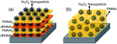
In this study, to investigate the effect of the spatial orientation structure of Fe3O4 nanoparticles on the magnetic properties of polymer nanocomposite thin films, we prepared two types of composite thin films: (i) a hybrid multilayer of alternating polymer layers and iron oxide nanoparticle monolayers, and (ii) a spin-coated polymer thin film with homogenously dispersed iron oxide nanoparticles (Fig. 1). Transmission electron microscopy (TEM) was used to check the lateral orientations of the Fe3O4 nanoparticles after LB deposition, whereas neutron reflectivity (NR) and X-ray reflectivity (XRR) were employed to measure the layered structure of the nanoparticle–PMMA multilayer and the distribution of nanoparticles in PMMA matrix for the spin-coated nanocomposite thin films, respectively. From the SQUID results, the nanoparticle assembly structure was found to correlate with magnetic properties of the hybrid polymer nanocomposite thin films, implying that the control of nanoparticle orientation is important for practical application of soft magnetic composite materials.


image file: c6ra10026k-f1.tif
Fig. 1 Schematic of (a) a hybrid multilayer of alternating PMMA/dPMMA layers and iron oxide nanoparticle monolayers deposited by floating and LB techniques and (b) a spin-coated polymer thin film embedded with homogenously dispersed iron oxide nanoparticles.

2. Experimental

2.1 Materials

Fe3O4 nanoparticles were obtained from Sigma-Aldrich (St. Louis, MO, USA). PMMA (Mw = 92 K, PDI = 1.08) and its deuterated polymer dPMMA (Mw = 144 K, PDI = 1.6) were purchased from Polymer Source Inc. (Dorcal, Quebec, Canada). All solvents were obtained from Sigma-Aldrich.

2.2 Thin film preparation

Si (100) wafers (LG Siltron Corp., South Korea) were treated by UV-ozone cleaning method for 20 min and then immersed in diluted hydrofluoric acid solution (H2O[thin space (1/6-em)]:[thin space (1/6-em)]HF = 10[thin space (1/6-em)]:[thin space (1/6-em)]1 vol) for 30 s at 21 °C. The HF-etched substrates were then washed two times with DI water and dried with N2 gas before film coating. For the multilayer sample, dPMMA and PMMA were chosen to provide a good contrast for neutron. dPMMA was dispersed at the concentration of 5 mg mL−1 in toluene. After syringe filtration with a PTFE membrane (0.5 μm, Millipore, Billerica, MA, USA), the dPMMA solution was rapidly spun cast onto HF-etched Si wafers at 2500 rpm for 30 s. The layer thickness was measured to be 178 ± 14 Å using NR. In order to prepare the ordered Fe3O4 nanoparticle monolayer, we applied the LB technique. The solution of Fe3O4 nanoparticles (750 μL, 1 mg mL−1) in toluene was spread on the water subphase (total area (A) = 780 cm2) at 20 °C and pH 7.4 in a LB trough (KSV 2000, KSV NIMA, Espoo, Finland). After 15 min, the Fe3O4 film was compressed at a speed of 5 cm2 min−1 while monitoring the surface pressure–area (πA) isotherm using a 25 mm-wide platinum Wilhelmy plate suspended from a microbalance by a motor-controlled barrier with feedback. After the desired surface pressure was achieved, the film was then vertically transferred on the spun-cast film surface. The thin film sample was annealed at 80 °C for 3 h in order to remove the remaining water and allow the nanoparticles to adhere to the PMMA surface. The PMMA was then dissolved in toluene (5 mg mL−1), spun cast onto the UV-ozone-treated hydrophilic Si wafer (thickness = 190 ± 16 Å), and carefully floated from DI water onto the prepared LB film. For the third and fourth layers, we repeated alternating depositions using the same procedure. For comparison, we also prepared a PMMA nanocomposite thin film embedded with homogeneously dispersed Fe3O4 nanoparticles. We added 17.6 wt% Fe3O4 nanoparticles into the PMMA solution in toluene (13 mg mL−1) and then spin coated the film on an HF-etched silicon wafer at 2500 rpm for 30 s.

2.3 Neutron and X-ray reflectivity

NR experiments were conducted with the REF-V reflectometer at the Cold Neutron Laboratory Building of the HANARO at the Korea Atomic Energy Research Institute (Daejeon, Korea). The wavelength (λ) is 4.75 Å, and ΔQ/Q ranges from 0.02 to 0.06. NR data were collected as a function of qz = (4π/λ[thin space (1/6-em)]sin[thin space (1/6-em)]θ), where θ is the grazing angle of incidence. The vertical and horizontal slits were set to 1.5 and 30 mm, respectively. The NR data were first corrected for footprint and background. The physical quantities used to fit the data were thickness, interfacial root-mean-square (rms) roughness (σ), and scattering length density (SLD) corresponding to the elastic coherent scattering per unit volume, which is crucial in the study of multilayer systems. XRR was also conducted using a Bruker AXS-D8 Advance diffractometer (CuKα radiation, λ = 1.54 Å).

2.4 Magnetic property measurements

Magnetization curves (magnetization versus applied magnetic field, MH curves) were recorded at two temperatures (2 and 300 K; below the blocking temperature and around room temperature, respectively) using a commercial magnetic property measurement system from Quantum Design (MPMS-XL7 with evercool; San Diego, California, USA). The magnetic field was applied parallel to the plane of the thin films. To compare the magnetization data from different samples, hysteresis loops were normalized to the saturation magnetization.

2.5 TEM measurement

TEM analysis was performed on a Philips Tecnai F20 (200 kV). The Fe3O4 nanoparticle monolayer was deposited on a carbon-coated copper grid using the LB technique and dried under vacuum at room temperature for two days.

3. Results and discussion

The average iron oxide nanoparticle size was determined from the TEM results to be 7.3 ± 0.1 nm (Fig. 2e). Since the particle surfaces were functionalized with oleic acid, the particles were stably dispersed in toluene, tetrahydrofuran, and chloroform without particle aggregation, facilitating the formation of Langmuir monolayers. We spread this nanoparticle suspension at the air–water interface to obtain the single-layer nanoparticle array. During the compression of the Fe3O4 nanoparticle, we monitored the surface pressure, π (mN m−1), as a function of area–mass density (m2 g−1), which was obtained by dividing the total trough area by the mass of iron oxide nanoparticles spread on the water subphase. Fig. 3 shows the πA isotherm results for the Langmuir monolayers of Fe3O4 nanoparticles. These results indicate that an abrupt onset pressure was obtained at an area of 48 m2 g−1 and the pressure began to increase linearly up to ∼45 mN m−1. We obtained a similar isotherm result during compression for the sample preparation of Fe3O4 monolayer of 33 mN m−1 (Fig. S2). Upon further compression of the monolayer, the slope of the curve tended to decrease due to the collapse of the monolayer; the film was observed to buckle on the water subphase.
image file: c6ra10026k-f2.tif
Fig. 2 TEM images of an Fe3O4 nanoparticle LB monolayer (a), (b) before and (c) and (d) after compression at the surface pressure of 20 mN m−1. (e) Nanoparticle size distribution histogram. The average particle size was 7.3 nm.

image file: c6ra10026k-f3.tif
Fig. 3 Surface pressure (π)–area (A) isotherm recorded for Fe3O4 nanoparticles at the air–water interface at pH 7.4 and 20 °C. An abrupt onset pressure was obtained at the area of 48 m2 g−1.

We transferred the nanoparticle monolayers at the air–water interface to a HF-etched silicon substrate or a carbon-coated TEM grid via LB deposition. We were able to achieve large-scale sample deposition with closely packed monolayers on a silicon substrate with a diameter of 4 in. We employed TEM to confirm the formation of monolayers of Fe3O4 nanoparticles and observe the nanoparticle assembly process as a function of the surface pressure after LB deposition. TEM results showed that the Fe3O4 nanoparticles formed closely packed monolayers without any particle aggregation. From Fig. 2a and b, we found that the nanoparticles formed a domain structure on the water immediately after spreading, resulting in no increase in surface pressure. However, the domains consisted of nanoparticle monolayers without particle aggregation or structural collapse. Upon monolayer compression, the domains merged into a long-range ordered monolayer without collapse at 20 mN m−1 (Fig. 2c and d). We also obtained the consistent TEM result in a large area (Fig. S1). The nanoparticles became closely packed, and the particle–particle distance could then be changed. This control over the interparticle distance and assembled structure is important for magnetic properties since dipole interactions are affected by the spatial orientations of particles (see SQUID results in Fig. 5 for more detail).


image file: c6ra10026k-f4.tif
Fig. 4 (a) Neutron specular reflectivity profiles for a single layer of nanoparticles on a dPMMA film and for the alternately deposited Fe3O4 nanoparticle–PMMA/dPMMA multilayer sample (solid lines are the best fits to the data). (b) The corresponding scattering length density (SLD) profiles. (c) X-ray reflectivity profile for the spin-coated PMMA nanocomposite thin film containing 17.6 wt% Fe3O4 nanoparticles (the solid line is the best fits to the data) and (d) the corresponding normalized electron density profile.

image file: c6ra10026k-f5.tif
Fig. 5 (a) Normalized magnetization versus applied magnetic field H for the Fe3O4 nanoparticle–PMMA multilayer and single-layer samples at 2 and 300 K (inset shows M × H full-range curves). (b) Normalized magnetization versus field curves at 2 K for the Fe3O4 nanoparticle LB monolayer films as a function of surface pressure with the external magnetic field parallel to the film surface (c) M × H full range curves for the polymer–Fe3O4 nanoparticle composite thin film with homogeneous particle distribution.

The polymer–Fe3O4 particle thin film was prepared by the alternating deposition of polymer layers and iron oxide nanoparticle assembled layers from floating and LB techniques (see the Experimental section for more detail). To characterize the multilayer structure with a good contrast between each layer, PMMA and dPMMA thin films were alternately deposited with nanoparticle monolayers at their interface (a schematic of the sample geometry is illustrated in Fig. 1). Fig. 4a shows the NR profiles for the monolayer and multilayer samples. The nanoparticle–polymer hybrid thin films on the substrates exhibit distinct fringes that are related to the sample thickness. To analyze the reflectivity data for the multilayer sample, we employed the following multilayer model: silicon substrate, silicon oxide, dPMMA1, nanoparticle layer1, PMMA2, nanoparticle layer2, dPMMA3, nanoparticle layer3, PMMA4, and nanoparticle layer4 (as illustrated in Fig. 1a). Each layer of nanoparticles was also divided into five layers due to their spherical shapes. In the figure, the symbols are the experimental data, and the solid lines correspond to the best fits to the data based on the SLD model profiles shown in Fig. 4b. According to the fitting results, the average thickness of the polymer layer films and Fe3O4 monolayers were 17.8 ± 1.4 and 9.7 ± 0.8 nm, respectively. This nanoparticle size is in good agreement with that determined from the TEM image in Fig. 2. We also obtained the coverage of Fe3O4 nanoparticle LB monolayers by dividing the measured SLD of the nanoparticle layer by the expected Fe3O4 bulk SLD value. The average coverage value was obtained to be 36 ± 6%. For comparison, the fractional surface coverage was also estimated from the TEM image (Fig. 2b). The TEM-based fractional surface coverage was 51%, which is higher than the NR-based coverage. This discrepancy is likely due to the reduced SLD value caused by oleic acid and the spherical shapes of the Fe3O4 nanoparticles. Furthermore, the TEM only probes a small area, whereas the neutron beam covers nearly the entire length of the sample.

We also prepared PMMA thin films embedded with Fe3O4 nanoparticles for comparison. Solutions of PMMA containing 17.6 wt% Fe3O4 nanoparticle were spun cast on an HF-etched silicon substrate. This sample had the same nanoparticle content (17.6 wt%) as the multilayer sample. XRR was performed for this spin-coated polymer composite thin film to measure the distribution of Fe3O4 nanoparticles in the PMMA matrix. Fig. 4c shows the XRR profile, which exhibits several fringes with the same frequency. The normalized electron density profile in Fig. 4d shows that the composite thin film had a uniform electron density value, indicating that the nanoparticles in the sample were homogenously distributed in the PMMA matrix, as illustrated in Fig. 1b.

To investigate the magnetic properties of the polymer nanocomposite thin film, we performed SQUID measurements. Fig. 5a shows the MH hysteresis loops for the Fe3O4 nanoparticle LB monolayer at 2 and 300 K. The magnetization curves as functions of the applied magnetic field recorded at 300 K show reversible behavior with zero coercivity, indicating superparamagnetic behavior. In contrast, the MH curve at 2 K displays hysteresis with a coercivity of 217 Oe, in agreement with ferrimagnetic states. Fig. 5b compares the magnetic behaviors of Fe3O4 LB monolayers (2 K) and different surface pressures. The MH hysteresis results show that the obtained coercivity values were similar for the samples at different pressures. The remanence-to-saturation magnetization ratios (Mr/Ms) ratios at 2 K varied from the monolayer at 10 mN m−1 (0.07) to the closely packed monolayer at 33 mN m−1 (0.25), suggesting that the dipolar interaction between nanoparticles increased with increasing monolayer compression. This observation is consistent with the slope of the MH curve at 2 K as a function of surface pressure. The closely packed Fe3O4 monolayer deposited at 33 mN m−1 exhibited a steeper increase in magnetization with the magnetic field, compared to the monolayer at 10 mN m−1. This higher sensitivity of the tightly packed nanoparticles suggests that their moments aligned in the plane of the substrate due to dipolar interactions. One can see from Fig. S3 and S4 that reproducible results of MH curve were obtained for each sample. There is no significant difference between data for zero field cooling (ZFC) and field cooling (FC). The coercivity of the Fe3O4 nanoparticle–PMMA multilayer sample was also similar to that of the monolayer of Fe3O4 nanoparticles (Fig. 5a). However, the Mr/Ms of the multilayer (0.48) was higher than that of the monolayer of Fe3O4 nanoparticles (0.25). Also, the saturation field in the MH curve becomes higher. These results are likely attributed to the dipolar interactions between nanoparticles of adjacent layers. However, for spin-coated polymer thin films embedded with homogenously dispersed iron oxide nanoparticles, the remanent magnetization and coercivity of the composite are zero at 2 and 300 K (Fig. 5c). Furthermore, a constant increase in the MH curve was seen without saturation, indicating that the sample was composed of completely isolated nanoparticles without dipolar interactions, in agreement with the XRR results shown in Fig. 4c and d.

4. Conclusion

In order to investigate the effect of the spatial orientations Fe3O4 nanoparticles on the magnetic properties of polymer nanocomposite thin films, we prepared multilayers of alternating spin-coated PMMA thin films and closely packed nanoparticle monolayers. We employed the LB technique to form Fe3O4 nanoparticle monolayers. The oriented structure of the Fe3O4 nanoparticle monolayer was verified through TEM. The layer structure along with film depth was characterized by NR after the alternating deposition of PMMA and dPMMA layers with nanoparticle monolayers at the interface. To investigate the magnetic properties of the polymer nanocomposite thin film, we also performed SQUID measurements. The dipole–dipole interactions between nanoparticles were significantly affected by particle orientation. However, the polymer–Fe3O4 nanoparticle composite thin films with homogeneous particle distributions exhibited zero remanent magnetization and coercivity due to the isolation of the nanoparticles and the reduction in the interparticle interactions.

Acknowledgements

This work was supported primarily from a grant from by the National Research Foundation of Korea under Contract No. 2012M2A2A6004260.

References

  1. Q. Dai, D. Berman, K. Virwani, J. Frommer, P.-O. Jubert, M. Lam, T. Topuria, W. Imaino and A. Nelson, Nano Lett., 2010, 10, 3216 CrossRef CAS PubMed.
  2. A. Moser, K. Takano, D. T. Margulies, M. Albrecht, Y. Sonobe, Y. Ikeda, S. Sun and E. E. Fullerton, J. Phys. D: Appl. Phys., 2002, 35, R157 CrossRef CAS.
  3. S. Sun, C. Murray, D. Weller, L. Folks and A. Moser, Science, 2000, 287, 1989 CrossRef CAS PubMed.
  4. M. Suda and Y. Einaga, Angew. Chem., 2009, 121, 1786 CrossRef.
  5. V. Sencadas, P. Martins, A. Pitães, M. Benelmekki, J. L. Gómez Ribelles and S. Lanceros-Mendez, Langmuir, 2011, 27, 7241 CrossRef CAS PubMed.
  6. P. Martins, C. Costa, M. Benelmekki and S. Lanceros-Mendez, J. Nanosci. Nanotechnol., 2012, 12, 6845 CrossRef CAS PubMed.
  7. W. Liu, A. E. Miroshnichenko, D. N. Neshev and Y. S. Kivshar, ACS Nano, 2012, 12, 6845 Search PubMed.
  8. J. Alam, U. Riaz and S. Ahmad, J. Magn. Magn. Mater., 2007, 314, 93 CrossRef CAS.
  9. G. Bidan, O. Jarjayes, J. M. Fruchart and E. Hannecart, Adv. Mater., 1994, 6, 152 CrossRef CAS.
  10. N. Nasongkla, E. Bey, J. Ren, H. Ai, C. Khemtong, J. S. Guthi, S.-F. Chin, A. D. Sherry, D. A. Boothman and J. Gao, Nano Lett., 2006, 6, 2427 CrossRef CAS PubMed.
  11. H. Xu, L. Cui, N. Tong and H. Gu, J. Am. Chem. Soc., 2006, 128, 15582 CrossRef CAS PubMed.
  12. T. Ninjbadgar and D. F. Brougham, Adv. Funct. Mater., 2011, 21, 4769 CrossRef CAS.
  13. S. B. Kim, C. Cai, S. Sun and D. A. Sweigart, Angew. Chem., Int. Ed., 2009, 48, 2907 CrossRef CAS PubMed.
  14. S. Rittikulsittichai, B. Singhana, W. W. Bryan, S. Sarangi, A. C. Jamison, A. Brazdeikis and T. R. Lee, RSC Adv., 2013, 3, 7838 RSC.
  15. L. Chen, L. Li, H. Zhang, W. Liu, Y. Yang, X. Liu and B. Xu, RSC Adv., 2014, 4, 46806 RSC.
  16. N. Pramanik, J. De, R. K. Basu, T. Rath and P. P. Kundu, RSC Adv., 2016, 6, 46116 RSC.
  17. B. Srinivasan, Y. Li, Y. Jing, Y. Xu, X. Yao, C. Xing and J. P. Wang, Angew. Chem., Int. Ed., 2009, 48, 2764 CrossRef CAS PubMed.
  18. A. Fu, W. Hu, L. Xu, R. J. Wilson, H. Yu, S. J. Osterfeld, S. S. Gambhir and S. X. Wang, Angew. Chem., 2009, 121, 1648 CrossRef.
  19. M. Riskin, B. Basnar, Y. Huang and I. Willner, Adv. Mater., 2007, 19, 2691 CrossRef CAS.
  20. Y. w. Jun, J. H. Lee and J. Cheon, Angew. Chem., Int. Ed., 2008, 47, 5122 CrossRef CAS PubMed.
  21. L. Wang, M. Wang, P. D. Topham and Y. Huang, RSC Adv., 2012, 2, 2433 RSC.
  22. N. A. Frey, S. Peng, K. Cheng and S. Sun, Chem. Soc. Rev., 2009, 38, 2532 RSC.
  23. J. Guo, X. Zhang, H. Gu, Y. Wang, X. Yan, D. Ding, J. Long, S. Tadakamalla, Q. Wang, M. A. Khan, J. Liu, X. Zhang, B. L. Weeks, L. Sun, D. P. Young, S. Wei and Z. Guo, RSC Adv., 2014, 4, 36560 RSC.
  24. C. J. Bae, S. Angappane, J. Park, Y. Lee, J. Lee, K. An and T. Hyeon, Appl. Phys. Lett., 2007, 91, 102502 CrossRef.
  25. P. Poddar, T. Telem-Shafir, T. Fried and G. Markovich, Phys. Rev. B, 2002, 66, 060403 CrossRef.
  26. B. P. Pichon, P. Louet, O. Felix, M. Drillon, S. Begin-Colin and G. Decher, Chem. Mater., 2011, 23, 3668 CrossRef CAS.
  27. S. Xuan, Y.-X. J. Wang, J. C. Yu and K. Cham-Fai Leung, Chem. Mater., 2009, 21, 5079 CrossRef CAS.
  28. Y.-w. Jun, J.-w. Seo and J. Cheon, Acc. Chem. Res., 2008, 41, 179 CrossRef CAS PubMed.
  29. N. Venkatesha, S. M. Pudakalakatti, Y. Qurishi, H. S. Atreya and C. Srivastava, RSC Adv., 2015, 5, 97807 RSC.
  30. L. Wu, C. Yang, Z. Lv, F. Cui, L. Zhao and P. Yang, RSC Adv., 2015, 5, 50557 RSC.
  31. J. Park, K. An, Y. Hwang, J.-G. Park, H.-J. Noh, J.-Y. Kim, J.-H. Park, N.-M. Hwang and T. Hyeon, Nat. Mater., 2004, 3, 891 CrossRef CAS PubMed.
  32. D. Mishra, M. Benitez, O. Petracic, G. A. B. Confalonieri, P. Szary, F. Brüssing, K. Theis-Bröhl, A. Devishvili, A. Vorobiev and O. Konovalov, Nanotechnology, 2012, 23, 055707 CrossRef CAS PubMed.
  33. K. Ariga, Y. Yamauchi, T. Mori and J. P. Hill, Adv. Mater., 2013, 25, 6477 CrossRef CAS PubMed.
  34. P. Degen, M. Paulus, M. Maas, R. Kahner, S. Schmacke, B. Struth, M. Tolan and H. Rehage, Langmuir, 2008, 24, 12958 CrossRef CAS PubMed.
  35. D. K. Lee, Y. H. Kim, C. W. Kim, H. G. Cha and Y. S. Kang, J. Phys. Chem. B, 2007, 111, 9288 CrossRef CAS PubMed.
  36. F. Mammeri, Y. L. Bras, T. J. Daou, J.-L. Gallani, S. Colis, G. Pourroy, B. Donnio, D. Guillon and S. Bégin-Colin, J. Phys. Chem. B, 2008, 113, 734 CrossRef PubMed.
  37. Y. Men, W. Wang, P. Xiao, J. Gu, A. Sun, Y. Huang, J. Zhang and T. Chen, RSC Adv., 2015, 5, 31519 RSC.
  38. B. P. Pichon, M. Pauly, P. Marie, C. Leuvrey and S. Begin-Colin, Langmuir, 2011, 27, 6235 CrossRef CAS PubMed.

Footnote

Electronic supplementary information (ESI) available: (1) TEM image of the Fe3O4 nanoparticle monolayer (2) πA isotherm of the Fe3O4 nanoparticle monolayer, (3) MH curves of Fe3O4 nanoparticle monolayer and polymer nanocomposite multilayer. See DOI: 10.1039/c6ra10026k

This journal is © The Royal Society of Chemistry 2016
Click here to see how this site uses Cookies. View our privacy policy here.