
In situ synthesis of porous SnO2 nanospheres/graphene composite with enhanced electrochemical performance
Youwen Yang*a,
Yuanhao Gaob,
Ting Chengb,
Dongming Mab,
Jiguang Liua and
Xueliang Lib
aSchool of Materials Science and Engineering, Hefei University of Technology, Hefei, 230009, Anhui Province, P. R. China. E-mail: hfutyyw@hfut.edu.cn
bSchool of Chemistry and Chemical Engineering, Hefei University of Technology, Hefei, 230009, Anhui Province, P. R. China
First published on 5th July 2016
Abstract
A large diameter porous SnO2 nanospheres/graphene composite (p-SNG) was synthesized by a one-pot in situ hydrothermal method for the first time. XRD studies and FE-SEM, TEM images indicate that the porous SnO2 nanospheres with diameters of about 200 nm are distributed on the graphene nanosheets (GNS) uniformly. In comparison with the bare SnO2 nanospheres, the as-synthesized p-SNG exhibited enhanced initial charge and discharge capacity, superior cycle performance and rate performance. Electrochemical measurements demonstrated that the p-SNG composite delivered a reversible discharge capacity of 921.5 mA h g−1 at a current density of 400 mA g−1 after 50 cycles and a rate performance of 802.9 mA h g−1 at a high current density of 1600 mA g−1.
1. Introduction
Lithium ion batteries (LIBs) are considered to be one of the most suitable candidates to satisfy the requirements of modern electronic devices because of their high energy density, high voltage, and light weight. For the purpose of improving the electrochemical performance of LIBs, one of the most researched areas is the development of novel anode materials. To date, there are three main methods to improve the electrochemical performance of anode materials: (1) nanocrystallization, that is reducing the materials size to nanoscale in order to enhance the anode lithium storage capacity and strain intensity, such as nanowires,1,2 nanospheres,3 hollow nanostructures,4 etc. (2) alloying, that is using the special physical properties of active and inactive material, to reduce the volume expansion, crushing of anode electrode materials in the process of charging and discharging. The mainly research object includes Si-alloy,5 Sn-alloy,6 Sb-alloy,6,7 Ge-alloy8 etc. (3) composite structure, that means dispersing the lithium active particles into a conductive matrix to improve the conductivity and structural instability of the composite electrode, thus enhancing its cycle performance, such as Sn@C,9 CuS/graphene,10 SnO2/graphene11 etc.Tin dioxide (SnO2) with theoretical reversible specific capacities of 782 mA h g−1, which is twice as high as that of the conventional graphite, is considered to be one of the most promising anode materials. However, the main drawback associated with the performance of SnO2 as anode materials is its volume change (about 300%) that upon the lithiation/delithiation process,12 which limits its commercial application. To solve this problem, much effort has been devoted to optimizing the morphology, composition, structure, conductivity, and surface chemistry of SnO2 anode materials for high performance LIBs.13–15 Nanostructured electrode materials possess many advantages, such as increased number of electrochemical active sites and better control over stress due to the lithiation/delithiation process.16 GNS have been regarded as a good matrix for SnO2 anode since it has good mechanical properties, excellent electronic conductivity, high surface areas, and chemical stabilities.14 The high specific surface can provides large electrode–electrolyte contact area with better lithium ions access for efficient electrochemical reaction.17 Dispersed SnO2 nanocrystals on the graphene will help to stabilize the electrochemical interface further, thereby improving the Coulombic Efficiencies (CE) and cycle life as the anode materials. S. K. Park et al.18 reported a SnO2/graphene composites by a hydrothermal method, which exhibited a charge capacity of 819 mA h g−1 for the first cycle and retained a capacity of 626 mA h g−1 after 50 cycles at a current density of 100 mA g−1. A. Bhaskar et al.19 think that the key roles of graphene as the electron-conducting matrix for the SnO2 hollow spheres buffers the severe volume changes during cycling and inhibits electrode disintegration and rapid capacity fading, thus amplifying reversible capacity, rate capability, and cycling stability.
Obviously, fabricating the SnO2/graphene composite is considered as an effective strategy to improve the electrochemical performance of SnO2 anode. In many research, the SnO2 nanoparticles with small size (a few nanometers or dozens of nanometers) on graphene sheets were reported13,15–22 and little research has been focused on big size (>100 nm) SnO2. Recently, Cristina Botas23 reported the fabrication of SnO2/graphene composite with the diameter of SnO2 particles about 250 nm with the results of electrochemical tests show that the electrode exhibits good cycle performance and rate characteristic. In our previous work, we have reported the preparation of porous hollow SnO2 nanosphere.24 To the best of our knowledge, there is no report about p-SNG with large diameter by in situ hydrothermal method, of which the porous SnO2 diameter is greater than 100 nm. In this work, we have synthesized p-SNG composite with the large porous SnO2 (about 203.8 nm averagely in diameter) by the method of one-pot in situ hydrothermal for the first time. The obtained composite, in which porous SnO2 nanospheres were uniformly dispersed on the GNS, exhibited excellent cycling stability and rate performance as anode materials in LIBs.
2. Experimental section
2.1 Synthesis of the p-SNG
Graphene oxide (GO) was prepared from powdered flake graphite by the modified Hummer's method, and used as the precursor.25 In the typical synthesis, GO (30 mg) was added into distilled water (3 ml) with ethanol (30 ml), sodium dodecyl sulfate (SDS) (280 mg) was then added, followed by 1 h ultrasonication to make a homogeneous suspension. Then, SnCl2·2H2O (250 mg) and concentrated HCl (0.6 ml) were added into the suspension respectively. After 5 min of ultrasonic treatment, the mixture was dissolved in the mixture under magnetic stirring at room temperature for minutes. Finally, the resulting solution was transferred to 50 ml Teflon-lined stainless steel autoclave for the hydrothermal reaction. The autoclave was sealed and heated at 140 °C for 12 h in an electrical oven. After heating treatment, the autoclave was cooled to room temperature. Black products were obtained by centrifugation, washed with distilled water several times prior to be dried in vacuum at 60 °C.2.2 General characterization
The products were characterized by X-ray diffraction (XRD) with Cu Kα radiation (λ = 1.518 Å), as well as field emission scanning electron microscopy (FESEM), and high-resolution transmission electron microscopy (HRTEM). The functional groups in samples were characterized by Fourier transform infrared spectrometry (FT-IR). The composition analysis in samples were performed by X-ray photoelectron spectroscopy (XPS) in the region of 0–1400 eV. The Raman spectrometer was recorded on a LabRam HR Evolution confocal Raman spectrometer, with an excitation laser wavelength of 532 nm. Thermogravimetric analysis (TGA) was performed in air.2.3 Electrochemical characterization
The electrochemical properties of the p-SNG composite as anode materials in lithium ion cell was evaluated by galvanostatic charge/discharge technique. The test electrodes were prepared by mixing the samples with acetylene black and polyvinylidene fluoride in a weight ratio of 7![[thin space (1/6-em)]](https://www.rsc.org/images/entities/char_2009.gif) :2:1 in N-methylpyrrolidinone solvent. Then, the slurry was uniformly cast on a copper foil and dried at 90 °C under vacuum for 12 h. The coin cells were assembled inside an argon-filled glovebox using lithium metal foil as the counter electrode and the polypropylene as the separator. The electrolyte was 1 M LiPF6 dissolved in ethylene carbonate and dimethyl carbonate solvent (1:1 volume ratio). The cells were tested on a computer controlled battery tester system. The profiles of galvanostatically charging and discharging curves were obtained at a voltage range of 0.05 to 2.00 V (vs. Li+/Li) at a current density of 800 mA g−1. A galvanostatic cycling test of the assembled cells was carried out on a Land CT2001A system in the potential range of 0.05–2.00 V at a discharge/charge current density of 400 mA g−1.
:2:1 in N-methylpyrrolidinone solvent. Then, the slurry was uniformly cast on a copper foil and dried at 90 °C under vacuum for 12 h. The coin cells were assembled inside an argon-filled glovebox using lithium metal foil as the counter electrode and the polypropylene as the separator. The electrolyte was 1 M LiPF6 dissolved in ethylene carbonate and dimethyl carbonate solvent (1:1 volume ratio). The cells were tested on a computer controlled battery tester system. The profiles of galvanostatically charging and discharging curves were obtained at a voltage range of 0.05 to 2.00 V (vs. Li+/Li) at a current density of 800 mA g−1. A galvanostatic cycling test of the assembled cells was carried out on a Land CT2001A system in the potential range of 0.05–2.00 V at a discharge/charge current density of 400 mA g−1.
3. Result and discussion
3.1 Physicochemical and structural characterization
The XRD pattern obtained from p-SNG is shown in Fig. 1, together with GO (curve b) and graphite (curve c). As shown in curve a, the four dominant broadened peaks (110), (101), (211), and (301) are attributed to the SnO2 phase (JCPDS no. 41-1445), indicating the formation of tetragonal SnO2 nanocrystals. The peak at 11° in curve b is characteristic for GO with an interlayer spacing of 0.85 nm, resulting in facile exfoliation due to the weakened van der Waals forces between layers of GO.26 For the samples of p-SNG, no diffraction peaks of layered GO can be observed, indicating the absence of layer-stacking regularity after the reduction of GO.27 The diffraction peak of graphite at ca. 26.5° disappeared in the curve b, indicating the successful oxidation of raw graphite to GO.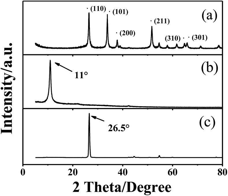 | ||
| Fig. 1 X-ray diffraction patterns for (a) p-SNG, (b) GO, (c) graphite. | ||
For quantifying the amount of graphene in the composite, TGA was carried out in air. The sample was heated from room temperature to 800 °C at rate of 10 °C min−1. As shown in the TGA curves (Fig. 2a), the p-SNG shows a rapid mass loss between 600 and 800 °C due to the oxidation of RGO. The bare SnO2 remains almost stable under 800 °C, so any weight change corresponds to the oxidation of graphene. Therefore, according to the change of weight, it is estimated that the amount of graphene in the composite was about 17.9%.
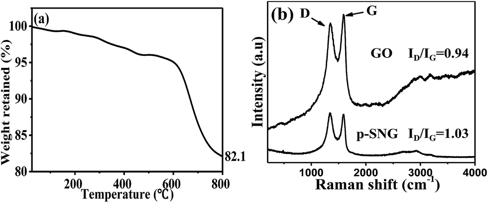 | ||
| Fig. 2 TGA curve of the p-SNG (a), Raman spectrum of the GO and the p-SNG (b). | ||
To further demonstrate the formation of composite and the structural changes, Raman spectroscopy was performed on p-SNG and GO, and the spectra are shown in Fig. 2b. Typical graphene peaks at about 1361 cm−1 (D band) and 1584 cm−1 (G band) are observed in both the GO and the p-SNG samples, which confirms the presence of the graphene in the composite. The D peak is associated with the disorder of graphene and the G peak corresponds to order sp2-bonded carbon atoms. The intensity ratio of the D to G band (ID/IG) was calculated as 0.94 for the GO and 1.03 for the p-SNG, so the increase intensity ration of D to G in p-SNG composite in comparison with the GO, which suggests an increase in the average size of the sp2 domains upon reduction of the exfoliated GO.
The surface composition and chemical states of the species in the p-SNG and GO are shown in Fig. 3. Fig. 3a and c show the spectra of C 1s from GO and the p-SNG samples. The peak of the C 1s spectrum can be fitted with four types of C including C–C (284.6 eV), C–O–H (286.7 eV), C![[double bond, length as m-dash]](https://www.rsc.org/images/entities/char_e001.gif) O (carbonyl carbon, 287.7 eV) and OC–O (carboxylate carbon, 289.2 eV) and can be discerned.28 The C 1s XPS spectrum of p-SNG composite shows the presence of the same functionalities (Fig. 3c) but with a much smaller contribution of the oxygenated functional groups, indicating the reduction of GO with Sn2+ ion in the deoxygenation process. The peaks of tin (Sn 3p, 3d, 4s, 4p, 4d) emerge, which are expected from SnO2, meanwhile, the peak of C 1s is attributed to RGO. As shown in the Fig. 3d, the Sn 3d5/2 and Sn 3d3/2 peaks of the SnO2 nanospheres are at 487.5 and 495.9 eV with an 8.4 eV peak-to-peak separation. It can confirms the formation of SnO2 nanoparticles, which are coupled on RGO. The O 1s XPS spectrum of GO is illustrated in Fig. 3e, which is deconvoluted into two peaks. The peaks at 532.2 and 533.1 eV are ascribed to CO and C–O–H of GO respectively. Due to the low reducibility of Sn2+, there are still small amounts of residual oxygenated groups left which are also observed in Fig. 3f. The presence of SnO2 can also be further confirmed by the O 1s XPS peak at 530.8 eV in Fig. 3f. Moreover, after analysis and calculation the C and O atomic ratio is 67:31, almost reach 2:1 confirms that the resulting GO is highly oxidized. And from the figure of the composite structure, the C and O atomic ratio is 78:15, almost reach 5:1. The ration of C:O is increased in p-SNG in comparison with GO also confirms the above conclusion that the GO was reduced by Sn2+ ion in the deoxygenation process. The quality of Sn and C ratio reached 1:1.32, almost the same as the result of the calculation with mass balance.
O (carbonyl carbon, 287.7 eV) and OC–O (carboxylate carbon, 289.2 eV) and can be discerned.28 The C 1s XPS spectrum of p-SNG composite shows the presence of the same functionalities (Fig. 3c) but with a much smaller contribution of the oxygenated functional groups, indicating the reduction of GO with Sn2+ ion in the deoxygenation process. The peaks of tin (Sn 3p, 3d, 4s, 4p, 4d) emerge, which are expected from SnO2, meanwhile, the peak of C 1s is attributed to RGO. As shown in the Fig. 3d, the Sn 3d5/2 and Sn 3d3/2 peaks of the SnO2 nanospheres are at 487.5 and 495.9 eV with an 8.4 eV peak-to-peak separation. It can confirms the formation of SnO2 nanoparticles, which are coupled on RGO. The O 1s XPS spectrum of GO is illustrated in Fig. 3e, which is deconvoluted into two peaks. The peaks at 532.2 and 533.1 eV are ascribed to CO and C–O–H of GO respectively. Due to the low reducibility of Sn2+, there are still small amounts of residual oxygenated groups left which are also observed in Fig. 3f. The presence of SnO2 can also be further confirmed by the O 1s XPS peak at 530.8 eV in Fig. 3f. Moreover, after analysis and calculation the C and O atomic ratio is 67:31, almost reach 2:1 confirms that the resulting GO is highly oxidized. And from the figure of the composite structure, the C and O atomic ratio is 78:15, almost reach 5:1. The ration of C:O is increased in p-SNG in comparison with GO also confirms the above conclusion that the GO was reduced by Sn2+ ion in the deoxygenation process. The quality of Sn and C ratio reached 1:1.32, almost the same as the result of the calculation with mass balance.
 | ||
| Fig. 3 XPS C 1s of the GO (a), XPS full spectra of GO (b), C 1s of the p-SNG (c), XPS full spectra of p-SNG (d), O 1s of the GO (e); p-SNG (f). | ||
Fig. 4 represents the FESEM and TEM images of p-SNG material. It is evident that the resulting composite appears layered structure and pleated from the Fig. 4a. The surface of graphene distributes some SnO2 nanospheres, these nanospheres tightly bound on the surface of graphene, still not fall off even ultrasounded 10 min, which indicates that SnO2 and graphene have a strong interface bonding force. As can be seen from Fig. 4b, p-SNG composite exhibits a spherical three-dimensional porous structure. TEM (Fig. 4b) confirmed the FESEM results and showed that a lot of uniformly SnO2 nanospheres were very homogeneously and closely anchored on the GNS to form the composites. It can be seen from the low magnification TEM image (Fig. 4b) that these nanospheres are uniformly distributed, the number of the nanospheres distributed in folds of graphene is larger compared to the region of stretch. After calculation, the average size of the SnO2 nanospheres is 203.8 nm with a standard deviation of 14.9 nm. From the further amplification of high-magnification TEM image of single SnO2 nanospheres in the Fig. 4b, we can see that SnO2 nanospheres are not smooth, they are composed of many small SnO2 nanocrystals. These crystals radially outwardly orderly, and get together to form the porous structure similar with durian-shaped. As shown in the HRTEM image (Fig. 5c) the space of crystal plane is 0.346 nm and 0.267 nm, corresponding to (110) and (101) plane of the tetragonal rutile SnO2 respectively.
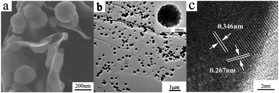 | ||
| Fig. 4 FE-SEM images of p-SNG (a), TEM (b) and HRTEM (c) images p-SNG. | ||
 | ||
| Fig. 5 Charge–discharge curves (a) and cycle performance (b) rate performance (c) of the p-SNG. | ||
Investigation of how SnO2 nanoparticles are immobilized or anchored on the graphene nanosheets is very relevant for the formation of resultant composites achieving desired performance.24 In our study, we adopted a convenient in situ method to fabricate RGO decorated with SnO2 nanospheres. The transformation of two substances are involved in the process of hydrothermal strategy. The Sn2+ transformed to SnO2 through the oxidation reaction with its valence state increased under hydrothermal conditions according to equation, meanwhile, the reaction that the GO was reduced to RGO under hydrothermal conditions with Sn2+. The formation of SnO2 is represented by the following equation:
| 2Sn2+ + O2 + 2H2O → 2SnO2 + 4H+ |
In this work, natural flake graphite is oxidized by the Hummers method, the distance between the layers of graphite is increased due to the formation of produce hydroxyl, carboxyl, carbonyl and other groups. And under the influence the upper hydrophilic group, it dispersed in the solution, obtained a highly dispersed GO. As shown in Scheme 1, monolayer GO, under the action of a surfactant, agglomeration between them was disappeared, stabilized the dispersion of GO. After refluxed at 160 °C for 12 h, the GO nanosheets were reduced to RGO, Sn2+ was then added, and a large number of active groups were anchored on the surface of RGOs. In the hydrothermal process, Sn2+, HCl ethanol and other reducing substances reducing GO to graphene, and after nucleation and growth, Sn2+ was transformed to primary SnO2 nanospheres. Eventually these particles, after growth, reunion and curing, formed porous SnO2 nanospheres, and more evenly distributed in the graphene surface, formed the p-SNG composite.
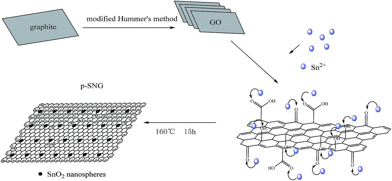 | ||
| Scheme 1 Schematic formation process of p-SNG structure. | ||
As we known, the RGO are very prone to irreversible aggregation or restacking due to the strong van der Waals forces among individual GO nanosheets.29 After sonication, the original structure loosely layered of GO was destroyed, the distance between the layers was increased, which leading to the influence of van der Waals forces gradually weaken. And most RGO was separated by nanospheres, SnO2 nanospheres can interact with RGO through physisorption, electrostatic binding or charge transfer interactions.30 By incorporation of nanospheres into RGO, the aggregation problem of RGO could be minimized or prevented, favoring the maintenance of high surface area and other intrinsic chemical and physical properties of graphene.31
3.2 Electrochemical characterization
The discharge–charge curves for the 1st, 2nd, 10th and 60th cycles of the electrodes made with p-SNG, carried out in the voltage range of 0.05–2.0 V (vs. Li) at a current density of 800 mA g−1, are demonstrated in Fig. 5a. In the first discharge profile, the composite shows two voltage plateaus between 1.0–0.7 V and 0.5–0 V similar to the porous nanospheres-based anode electrodes. In the first cycle, the p-SNG delivers a high discharge capacity of 2005.7 mA h g−1 and the corresponding charge capacity is 989.1 mA h g−1, corresponding to a CE of about 49.32%. The specific capacity of the composite for Li can be substantially higher than that of porous SnO2 nanospheres (ref. 24, 1744.3 mA h g−1 and 861.4 mA h g−1 respectively) may because graphene can absorb lithium ions on both sides and the single layer of graphene provides a facile route for the diffusion of lithium ions.32 The large irreversible capacity observed in the first cycle may be caused by the conversion of SnO2 to Sn nanospheres, along with the formation of Li2O and the solid electrolyte interphase (SEI) layers.33 From the second cycle, the reversibility of the electrode was improved, showing an enhanced CE as high 96%, corresponding to the discharge capacity and charge capacity of 950.3 mA h g−1 and 920.6 mA h g−1 respectively.Fig. 5b shows the rate capability of p-SNG at different current densities. After 60 cycles, p-SNG can deliver a reversible capacity of 835.8 mA h g−1, it has exceeded the theoretical capacity of SnO2. To further demonstrate the electrochemical properties of composite materials, the rate performances of the p-SNG electrodes were then examined at various current densities in the range of 400–1600 mA g−1. As shown in Fig. 5c, the composite can delivers a reversible capacity of 1237.6 mA h g−1 at the current density of 400 mA g−1 after 10 cycles. The reversible capacity is declining with current density increasing. The composite can deliver a reversible capacity of 986.6 mA h g−1, 802.9 mA h g−1 and 596.9 mA h g−1 after 10 cycles, respectively. When the current density restored to 400 mA g−1, the electrode capacity can be recovered, the reversible capacity remains at 921.5 mA h g−1.
Compared to the as-synthesized pure hollow SnO2 nanospheres,24 the p-SNG possesses a greater initial charge and discharge capacity and superior cycle performance and rate performance. The improved electrochemical properties should be related to two factors: first, the stable interface formed by C–O covalent bonds not only improves the structural stability but also makes the anode structure more conductive than the semiconducting SnO2, thereby improving the CE and cycle life.34 Second, in the composite structure, RGO sheets act as a conductive support, on which SnO2 nanospheres are uniformly anchored. This ensures the electrochemical activity of the SnO2 nanoparticles because of good electron transfer.35 We think that the composite structure can display the synergetic effect between SnO2 nanospheres and RGO, which can avoid the agglomerate between RGO and the collapse of nanospheres in the process of charge/discharge. It clearly demonstrates that an intelligent nano composite which the RGO sheets decorated with metal oxide can drastically enhance the electrochemical performance of an electrode, especially SnO2 which generally suffer from a huge volume change during the lithiation/delithiation process.
4. Conclusions
In summary, we have synthesized p-SNG by a simple and effective method. The composite possesses more stable structure with large diameter can prevent the nanospheres agglomerate and the volume change of SnO2 during the lithiation/delithiation process. Due to the active function of the RGO in the composite and the porous nanospheres structure, p-SNG shows perfect lithium storage and more stable cyclability performance with excellent rate capability of 921.5 mA h g−1 at 400 mA g−1 after 50 cycles. Our results are beneficial to understanding the synthesis mechanism of the SnO2 nanospheres and graphene as the anode of LIBs with high cycling stability and charge/discharge rate. Nanostructures that use a graphene framework should also be capable of being more widely applied to other promising alloying reaction electrode in order to enhance electrochemical activities.Acknowledgements
The authors acknowledge the financial support from the National High Technology Research and Development Program of China Grant (No. 2013AA065502).Notes and references
- C. K. Chan, R. N. Patel, M. J. O'Connell, B. A. Korgel and Y. Cui, ACS Nano, 2010, 4, 1443–1450 CrossRef CAS PubMed.
- H. Kim and J. Cho, Nano Lett., 2008, 8, 3688–3691 CrossRef CAS PubMed.
- J. Shu, M. Shui, D. Xu, S. Gao, X. Li, Y. Ren, L. Hou, J. Cui, J. Xu and Z. Zhu, J. Electroanal. Chem., 2011, 657, 187–191 CrossRef CAS.
- Z. Wang and L. Zhou, Adv. Mater., 2012, 24, 1903–1911 CrossRef CAS PubMed.
- J. Wang, Y. Wang, P. Zhang, D. Zhang and X. Ren, J. Alloys Compd., 2014, 610, 308–314 CrossRef CAS.
- S. Yang, W. Yue, J. Zhu, Y. Ren and X. Yang, Adv. Funct. Mater., 2013, 23, 3570–3576 CrossRef CAS.
- C. Villevieille, C. M. Ionica-Bousquet, B. Ducourant, J. C. Jumas and L. Monconduit, J. Power Sources, 2007, 172, 388–394 CrossRef CAS.
- J. Cho, Electrochim. Acta, 2008, 54, 461–466 CrossRef CAS.
- X. Tao, R. Wu, Y. Xia, H. Huang, W. Chai, T. Feng, Y. Gan and W. Zhang, ACS Appl. Mater. Interfaces, 2014, 6, 3696–3702 CAS.
- C. Feng, L. Zhang, M. Yang, X. Song, H. Zhao, Z. Jia, K. Sun and G. Liu, ACS Appl. Mater. Interfaces, 2015, 7, 15726–15734 CAS.
- W. Li, D. Yoon, J. Hwang, W. Chang and J. Kim, J. Power Sources, 2015, 293, 1024–1031 CrossRef CAS.
- Y. Dong, Z. Zhao, Z. Wang, Y. Liu, X. Wang and J. Qiu, ACS Appl. Mater. Interfaces, 2015, 7, 2444–2451 CAS.
- H. Kim, S. W. Kim, Y. U. Park, H. Gwon, D.-H. Seo, Y. Kim and K. Kang, Nano Res., 2010, 3, 813–821 CrossRef CAS.
- H. T. Xu, H. J. Qiu, L. Fang, Y. Mu and Y. Wang, J. Mater. Chem. A, 2015, 3, 14887–14893 CAS.
- J. W. Jung, W. H. Ryu, J. Shin, K. Park and I. D. Kim, ACS Nano, 2015, 9, 6717–6727 CrossRef CAS PubMed.
- R. Thomas and G. M. Rao, J. Mater. Chem. A, 2015, 3, 274–280 CAS.
- Y. Zhu, H. Guo, H. Zhai and C. Cao, ACS Appl. Mater. Interfaces, 2015, 7, 2745–2753 CAS.
- S. K. Park, S. H. Yu, N. Pinna, S. Woo, B. Jang, Y. H. Chung, Y. H. Cho, Y. E. Sung and Y. Piao, J. Mater. Chem., 2012, 22, 2520–2525 RSC.
- A. Bhaskar, M. Deepa, M. Ramakrishna and T. Rao, J. Phys. Chem. C, 2014, 118, 7296–7306 CAS.
- B. Wang, D. Guan, Z. Gao, J. Wang, Z. Li, W. Yang and L. Liu, Mater. Chem. Phys., 2013, 141, 1–8 CrossRef CAS.
- W. Zhou, J. Wang, F. Zhang, S. Liu, J. Wang, D. Yin and L. Wang, Chem. Commun., 2015, 51, 3660–3662 RSC.
- D. Wang, X. Li, J. Wang, J. Yang, D. Geng, R. Li, M. Cai, T. K. Sham and X. Sun, J. Phys. Chem. C, 2012, 116, 22149–22156 CAS.
- C. Botas, D. Carriazo, G. Singh and T. Rojo, J. Mater. Chem. A, 2015, 3, 13402–13410 CAS.
- Y. Yang, D. Ma, T. Cheng, Y. Gao and G. Li, Nano, 2015, 10(6), 1550087 CrossRef CAS.
- W. Wang, Q. Hao, W. Lei, X. Xia and X. Wang, RSC Adv., 2012, 2, 10268–10274 RSC.
- Y. Li, X. Lv, J. Lu and J. Li, J. Phys. Chem. C, 2010, 114, 21770–21774 CAS.
- J. Zhang, Z. Xiong and X. Zhao, J. Mater. Chem., 2011, 21, 3634–3640 RSC.
- Z. Li, Y. Mi, X. Liu, S. Liu, S. Yang and J. Wang, J. Mater. Chem., 2011, 21, 14706–14711 RSC.
- Y. Li, Z. Li and P. K. Shen, Adv. Mater., 2013, 25, 2474–2480 CrossRef CAS PubMed.
- F. Li, J. Song, H. Yang, S. Gan, Q. Zhang, D. Han, A. Ivaska and L. Niu, Nanotechnology, 2009, 20, 455602 CrossRef PubMed.
- P. Lian, X. Zhu, S. Liang, Z. Li, W. Yang and H. Wang, Electrochim. Acta, 2011, 56, 4532–4539 CrossRef CAS.
- G. Xia, N. Li, D. Li, R. Liu, C. Wang, Q. Li, X. Lü, J. S. Spendelow, J. Zhang and G. Wu, ACS Appl. Mater. Interfaces, 2013, 5, 8607–8614 CAS.
- C. Zhong, J. Wang, Z. Chen and H. Liu, J. Phys. Chem. C, 2011, 115, 25115–25120 CAS.
- L. Miao, J. Wu, J. Jiang and P. Liang, J. Phys. Chem. C, 2012, 117, 23–27 Search PubMed.
- T. Chen, L. Pan, X. Liu, K. Yu and Z. Sun, RSC Adv., 2012, 2, 11719–11724 RSC.
| This journal is © The Royal Society of Chemistry 2016 |