
Improving the electrical conductivity and interface properties of carbon fiber/epoxy composites by low temperature flame growth of carbon nanotubes
Xusheng Du*a,
Feng Xuab,
Hong-Yuan Liua,
Yinggang Miaoab,
Wei-Guo Guob and
Yiu-Wing Maia
aCenter for Advanced Materials Technology (CAMT), School of Aerospace Mechanical & Mechatronic Engineering J07, University of Sydney, NSW 2006, Australia. E-mail: xusheng.du@sydney.edu.au; Fax: +61-2-9351-3760
bSchool of Aeronautics, Northwestern Polytechnical University, Xi'an, Shaanxi, P. R. China
First published on 11th May 2016
Abstract
Carbon nanotubes (CNTs) were grown in situ on carbon fibers (CFs) at low temperature (∼450 °C) in an ethanol combustion flame to develop multifunctional hierarchical reinforcements for epoxy resin matrices. Because of the low temperature, short duration and reducing atmosphere used in the flame growth process, there was no evident decrease of the tensile strength of the CFs. However, both the electrical conductivity and interfacial properties of the CFs were improved significantly after the CNTs were grown for only 3 minutes, resulting in >170% increase in in-plane electrical conductivity and ∼70% improvement in interfacial shear strength of the carbon fiber/epoxy composites. Electron microscopy studies revealed that both tip and root growth mechanisms were involved during the flame-induced synthesis. A good interfacial bonding strength between the CNTs and CFs was observed and could be attributed to the diffusion of metal catalyst particles into the CF surface and/or the carbon bonding between CNTs and CFs. Substantial improvements in electrical conductivity and interfacial properties without compromising the tensile strength of CFs after the flame growth of CNTs confirmed the efficiency and effectiveness of this method.
1. Introduction
The development of hierarchical multi-scale reinforcement for fiber reinforced polymer composites (FRPCs) by directly attaching or in situ growing CNTs onto the fiber surface has been demonstrated as an efficient method for improving the multifunctional properties of the composites, including their mechanical properties.1–3 For instance, after the deposition of CNTs onto SiC fibers, besides the improvements in damping properties and fracture toughness, the electrical conductivity and thermal dimensional stability of the FRPCs are also greatly increased owing to the good conductivity of the CNTs.3CNTs used in hierarchical CFs can be synthesized prior to or in situ grown. Quite a few methods have been developed to attach pre-synthesized CNTs onto the fiber surface, which include spreading a CNT powder4 or solvent paste,5 transferring CNT arrays6 and using electrophoresis7 or ‘dipping and freeze-drying’ methods,8–10 whereby the CNTs are uniformly deposited onto the carbon fabric surfaces from the CNT dispersion. Functionally modified CNT surfaces can strengthen the attachment of CNTs to the fibers by the chemical reactions between their functional groups.11 After the CNTs are grafted onto the CFs, two new interfaces are obtained: one is between CFs and CNTs, and the other is between CNTs and polymer matrix. Obviously, the interfacial property of the final composite depends on both the CNT/matrix interface and the CF/CNTs grafting force. In CF/CNTs composites, it is shown that the dominant failure mechanism is mainly controlled by the anchorage of CNTs on CFs.11
Carbon fiber is a multifunctional reinforcement for FRPCs due to its lightweight, good chemical and thermal stability, high electrical and thermal conductivities, and superior mechanical properties. It is suitable as a fiber substrate for in situ growth of CNTs since its high thermal stability can withstand the temperatures required for the process. Thus, multi-scale carbon-based reinforcement can be achieved by in situ growing CNTs onto CFs and this is found to be an efficient way to improving the interfacial properties of carbon fiber reinforced polymers (CFRPs).12 The advantages of this technique over those of attaching preformed CNTs mentioned above are better dispersion, higher density, and even control of orientation in the composites. Among the various in situ CNT growth methods, chemical vapor deposition (CVD) is the most utilized for growing CNTs onto CFs.12–19 Great interfacial improvement and good adhesion between CNTs deposit by CVD and CFs has been demonstrated17–19 and grafting of CNTs to CFs has been studied recently by Wang et al.19 Compared to the CVD methods, the flame growth of CNTs onto CFs is developed very recently and the strong adhesion of in situ flame synthesized CNTs on CFs has been proven by direct measurement of the force for peeling a single CNT from the CF surface.20 This result implies possible improvement of interfacial properties of CFRPs by flame growth of CNTs onto CFs. Also, oxygen-functional groups are found on the surfaces of flame synthesized CNTs,21–23 which is believed to be a distinct advantage over conventional CNTs by CVD. For example, glass fiber/vinyl ester composite laminates sprayed with flame synthesized CNTs display better mechanical properties than those reinforced with CNTs prepared by CVD owing to the particular structure of the flame synthesized CNTs containing abundant functional groups on their surfaces.21 The presence of organic groups on the surfaces of CNTs aids the diffusion of epoxy resin into the CNT forests on the CFs and improves the wetting of CF/CNTs with epoxy, which is an issue for this multi-scale carbon-based reinforcement.16
For in situ deposition of CNTs onto CFs, a great challenge is to prevent mechanical degradation of CFs, which was found in recent studies due to the intense heating using normal CVD techniques (usually above 650 °C with tens of minutes or even longer deposition times).15,18,24 In most engineering applications, it is highly desirable that the mechanical properties of CFs in the hierarchical carbon structure are retained. Since the flame synthesized CNTs usually takes a very short time, i.e., less than 5 minutes,20,23 the mechanical degradation of CFs is not expected if the synthesis temperature is also reduced.
Moreover, direct anchorage of CNTs on CFs enhances electric charge transfer between themselves more than those other techniques by attaching preformed CNTs onto CFs by van der Waals forces or chemical bonding via the organic molecules. Generally, the incorporated CNTs can bridge the adjacent CFs, creating better electrical and thermal conductive networks throughout the CFRPs. Considering the 0°/90° carbon fabric structure and the multi-ply nature of the CFRPs, the enhanced conductivity after deposition of CNTs onto CFs is bi-directional, i.e., in-plane and out-of-plane.7,25 It should also be noted that the method of in situ grown CNTs combines the steps of fabrication and dispersion of CNTs into one single step, which is simple, economical and efficient compared to those methods of attaching preformed CNTs. Thus, the great challenge of uniformly dispersing CNTs in the matrix is removed and the in situ grown CNTs without being damaged (likely induced during the dispersion step in the attaching methods) is realized, resulting in improvements of mechanical, electrical and/or thermal properties. However, to date, most work in this area is mainly focused on the mechanical properties improvement, such as fracture toughness and tensile strength, and limited information is available on the electrical characteristics.
In view of the above-mentioned advantages of in situ flame synthesized CNTs onto CFs, increased interfacial properties and electrical conductivities are well expected. In the present work, we further decrease the flame growth temperature reported previously20 and we demonstrate that this simple method allows CNTs to grow readily on CFs in several minutes to increase both IFSS and electrical conductivity while retaining the single fiber mechanical tensile strength characteristics. Moreover, compared to the extensive studies of CNT growth mechanisms on CFs by CVD, information on this more convenient flame synthesis process and associated CNT growth mechanism is limited; and these issues will be addressed in this work.
2. Experimental work
2.1 Materials
Carbon nanotubes were in situ deposited onto CFs (Inter-Turbine Advanced Logistics Pty Ltd) by the recently developed flame synthesis method and the technique was provided in detail in our previous studies.20,23 Typically, 0.2 mol L−1 nickel chloride (NiCl2) solution was employed as the catalyst precursor bath and an ethanol flame with a diameter of ∼4 cm was used as the carbon source. To grow the CNTs, the CF fabric wetted with the NiCl2 catalyst precursor was placed on a metal frame that was inserted into the flame ∼25 mm above the burner at a temperature about 450–520 °C. The metal frame was a stainless steel mesh with an aperture 1.0 mm2 square woven by 0.5 mm wires. In this way, the temperature for flame synthesis of CNTs onto CF fabrics could be reduced to as low as 450 °C due to the heat dissipation by the metal frame. The weight fractions of CNTs on the fabrics synthesized for 1 and 3 minutes are 7 and 12%, respectively. The temperature was measured by a Fluke 724 temperature calibrator connected to a thermocouple tip inserted in the CF fabric in the flame.The samples for single fiber pull-out tests were prepared according to the method reported previously26 and the epoxy matrix, Spurrs resin (PolySCI. Inc), was selected due to its low resin viscosity at ambient temperature and good wetting capability to facilitate successful pull-out tests of hierarchical CNTs/CF fibers over a range of embedded lengths. Spurrs resin consisted of four components: epoxy oligomers (ERL 4221), flexibilizer DER 736 (diglycidyl ether of polypropylene glycol), hardener (nonenyl succinic anhydride) and accelerator (dimethylaminoethanol). The epoxy was cured at 60 °C for 12 h. The embedded fiber length was adjusted by a MD-30 Plus image analysis system connected to an optical microscope. To study the effect of CNT length on the interfacial properties, CFs (diameter ∼5–8 μm) with CNTs grown for different times (1 and 3 minutes) were used to prepare the samples. At least five successful tests were recorded and the results calculated. Laminates with two plies of uni-directional carbon fabric for electrical conductivity measurements were fabricated by the hand lay-up method according to the process reported in ref. 23. CF fabrics with and without CNTs were utilized as the main reinforcement in CFRPs. For those laminates reinforced with CNTs grown on the CF fabrics, the two plies with the CNT forests sides were bonded face to face. The Spurrs epoxy system is not suitable as a matrix for CFRPs for infrastructure engineering owing to its high cost. An alternative commonly used epoxy system (electrical insulating like the Spurrs epoxy), i.e., Araldite-F (diglycidyl ether of bisphenol A, Huntsman) and hardener piperidine (Sigma-Aldrich) in weight ratio of 100![[thin space (1/6-em)]](https://www.rsc.org/images/entities/char_2009.gif) :5, was adopted for the electrical conductivity investigation on the CNTs decorated CFRPs. The whole process was maintained at 80–90 °C in order to ensure the low viscosity of the epoxy resin to fully impregnate the CF fabrics. The laminates were then wrapped with bleeders and a release film inside a vacuum bag, first vacuumed for 0.5 h followed by curing in a hot-press at 120 °C for 16 h under a pressure of 200 kPa. The fiber volume fraction in the final composite laminates was ∼58%.
:5, was adopted for the electrical conductivity investigation on the CNTs decorated CFRPs. The whole process was maintained at 80–90 °C in order to ensure the low viscosity of the epoxy resin to fully impregnate the CF fabrics. The laminates were then wrapped with bleeders and a release film inside a vacuum bag, first vacuumed for 0.5 h followed by curing in a hot-press at 120 °C for 16 h under a pressure of 200 kPa. The fiber volume fraction in the final composite laminates was ∼58%.
2.2 Characterization
Raman spectroscopy of the fabricated samples was performed on an Invia Renishaw Raman using a He–Ne laser at 633 nm wavelength. Scanning electron microscopy (SEM) images were taken on a Zeiss ULTRA Plus and optical images on a Leica microscope. Transmission electron microscopy (TEM) micrographs were obtained from a Philips CM12 (120 kV). The electrical conductivity was measured on a CHI electrochemical workstation with a two-probe method. Rectangular samples were cut along or transverse to the fiber direction from the CFRPs. To improve the electrical contact, silver paste was applied on the sides of the samples which were first polished with abrasive papers. Single fiber pull-out and tensile tests were conducted at a gauge length of 20 mm using an Instron 5567 testing machine with a load cell (2.5 N capacity) at a crosshead speed of 0.1 mm min−1 and ambient temperature. The fiber pull-out length (or embedded fiber length) was also confirmed by measuring the length of the matrix socket. SEM was used to investigate the interfacial failure mode of the pulled out samples by checking the failure surface of the inner socket wall and the fiber surface.3. Results and discussion
3.1 Low temperature flame growth of CNTs on CFs and the growth mechanisms
The temperature for the growth of CNTs in the ethanol flame was ∼450–520 °C, which was measured in situ by inserting the thermocouple tip into a CF bundle. The distribution of CNTs deposited on CFs in the flame range was uniform so that CNT growth occurred as low as 450 °C. Such a low temperature was clearly less than those (i.e., about 500–700 °C) reported in our previous work.20,23 To our best knowledge, this was the lowest temperature ever reported among the methods for ethanol flame growth of CNTs, and much lower than most other CNT deposition techniques, such as CVD, which is usually above 650 °C.12,15,17,18,24,27 In a recent study on the flame growth of solid carbon nanofibers onto carbon fabrics, an even higher temperature of up to 1000 °C was used.28 Compared to the clean CF (Fig. 1a), the surface of carbon fibers becomes darker and rougher after flame growth of CNTs. Many entangled CNTs can be seen on the CF surface (Fig. 1b). In the TEM image (Fig. 2a) most CNTs have a diameter of ∼20 nm, though thicker CNTs with diameter ∼50 nm are occasionally found. The thermal stability of the bare CFs in the flame has been shown previously,20,28 and it is believed that the reducing atmosphere in the ethanol flame protects the carbon fibers from combustion. Also, the intrinsic high thermal stability of CFs is a critical factor. Considering the importance of retaining the mechanical properties of CFs, the low temperature environment in our flame growth method helps prevent the mechanical degradation of CFs during CNT growth. The tensile behavior of single CFs with grown CNT forests will be discussed in Section 3.2.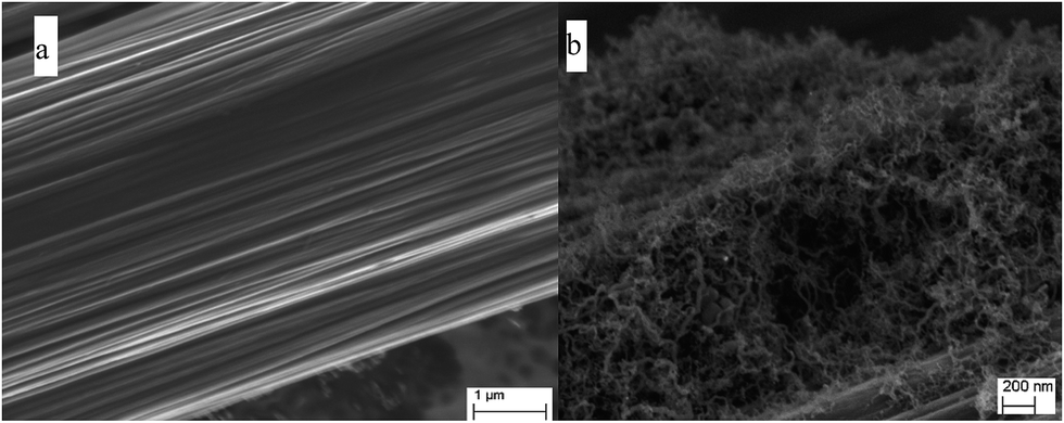 | ||
| Fig. 1 (a) SEM image of CF and (b) CF with CNT growth for 3 minutes. | ||
 | ||
| Fig. 2 (a–e) TEM images of CF/CNT and (f) SEM image of CF/CNT. | ||
High resolution electron microscopy was used to investigate the mechanisms of the flame growth of CNTs onto CFs. Different to many CVD processes, where pure metal catalyst particles were usually prepared prior to the deposition of CNTs, the nickel catalyst used here are formed in situ from a very cheap precursor NiCl2, in a form of Ni@C core–shell structure. This makes our flame growth method simpler and faster than most CVD processes and others for flame growth of carbon nanofibers onto CFs.28 Fig. 2b shows two such catalyst particles on the CF surface. The strong contrast between the core and the shell in the TEM image indicates they are different elements, i.e., the inner dark area of nickel is shelled by thin carbon layers. Indeed, such Ni@carbon core/shell nanostructures have already been reported in our previous work on the high temperature flame growth of CNTs.20 The HRTEM of the core/shell nanostructures was also shown in Fig. 2d, where the boundary between the core and shell was highlighted by the broken lines. In our previous work, such Ni@C core/shell particles were formed by the reaction between the Ni salt and the hydrocarbon species produced from the pyrolyzed polymers at 600 °C (ref. 29) or 700 °C.30 Since the Ni salt was dispersed and embedded in the polymer solid matrix, the direct interaction between Ni salt and polymer solid or melt at high temperature might be involved in forming the Ni catalyst. However, in this work, Ni particles are formed in situ in nanoscale at the interface at ∼450–520 °C owing to the initial seeding process whereby the redox reaction occurs between Ni2+ and the vapor of hydrocarbon species in the ethanol flame and randomly deposits the Ni nanoparticles at active local spots on the fiber surface from which CNTs grow. Even though the Ni catalyst particles may move along the axial direction of CNTs in the ensuing growth process (represented by black particles at the tips of CNTs in Fig. 2a and e) according to the tip growth mechanism,27 the grafting of CNTs onto CF is clearly built up and determines the initial stage of CNT growth. In the SEM image (Fig. 2f), the white particles at the tips of CNTs are the Ni catalyst and the roots always seem thicker than the other parts, which may be due to the interaction between the in situ growing carbon shell of the catalyst and the CF surface. Besides the tip growth mode, the root growth mechanism is also found to take place in the flame growth process, where the black catalyst particles are located at the root of the CNTs in the TEM image (Fig. 2c). It can be seen that the size of the black particle in the middle of Fig. 2c (see blue arrow) is ∼15 nm that is comparable to the diameter of the CNT growing from it. Interestingly, some Ni catalyst particles are much larger than the diameter of CNTs growing from them (see red arrows in Fig. 2c), indicating that the CNT diameter may not depend on the size of the catalyst particles in the root growth process. Similar CNT growth on larger catalyst particles have also been found in the CVD method, where the particle diameter (100–150 nm) exceeds that of the CNTs (10–15 nm), and many CNTs are observed to grow from individual particles.27 This characteristic feature of the flame synthesis method makes it a very convenient, fast and efficient CNT fabrication method.
By carefully studying the TEM images of many CNTs on CFs, we found that the majority (more than 90%) of the CNTs are formed by the root growth mechanism. This is reasonable since the Ni catalyst particle diameter should be comparable to the size of CNTs according to the tip growth mechanism (Fig. 2f); but there is no such restriction in the root growth process. In our simple flame growth method, the catalyst particles are in situ formed by thermal chemical reaction between NiCl2 and hydrocarbon species in the ethanol flame and thus no special control of the size of the Ni catalyst particles. This means fewer catalyst particles with appropriate sizes can be formed for the tip growth process. Also, metal particles are more likely to agglomerate and grow when the concentration of the fine metal catalyst particles is higher.14 Therefore, the amount of catalysts ready for the tip growth mechanism could be only a minority, while the majority of particles are in favor of the root growth mechanism. Similar root growth behavior of CNTs on CFs with metal catalyst diffusion into the CF substrate was also reported in the CVD methods.17,18 Root growth mode was also observed during the growth of CNTs onto a Ni-layer coated on a Cu substrate in an ethanol flame.21 Generally, the root growth mode is favored when there is strong interaction between the metal catalyst and the substrate facilitating the diffusion of catalyst particles into the substrate. However, the tip growth mode occurs when there is poor affinity between the catalyst and the substrate. Accordingly, the embedment of Ni particles in the carbon fiber substrate observed in Fig. 2b and c confirm the high activity of in situ synthesized Ni catalysts and the CNT root growth mode in our flame synthesis technique.
In the Raman spectra of CF and CNT/CF in Fig. 3, the presence of two strong peaks is consistent with graphitic carbon materials, which are commonly referred to as the D and G bands, respectively. The D peak is centered at 1348 cm−1 and the G peak at 1581 cm−1. That both the ID/IG ratios in the two samples are larger than 1 is due to the existence of disordered carbon structures, which are common in pyrolytic carbon materials. The almost identical ID/IG ratios after the flame growth of CNTs on CFs indicate similar and compatible carbon structures between CNT and CF, thus enabling good bonding between them which has been demonstrated by both SEM and micro-mechanical tests.20 All these suggest that the simple flame synthesis method provides an efficient route to fabricate integrated hierarchical carbon nanostructures. Hence, it is expected that the flame synthesized CNTs on CFs will promote interfacial stress and electron transfers between CFs and matrix in CFRPs.
 | ||
| Fig. 3 Raman spectra of CF/CNT and CF. | ||
3.2 Effect of flame growth of CNTs on single hierarchical carbon fiber tensile strength
Single fiber tensile test was used to investigate the effect of the flame synthesis on the strength of the CFs. Fig. 4 displays very similar tensile strengths for both bare and CNT grafted CFs. This shows that the growth of CNTs on the surface of the fiber does not give any evident decrease in fiber tensile strength (only a loss of 3.7%), confirming the distinct benefit of the flame growth method over other previously reported CVD techniques, whereby the tensile strengths are decreased to different extents.15,18,24 Qian et al. reported 35% (ref. 18) and 15% (ref. 24) reductions in tensile strength, and Sager et al. also reported a 30% reduction after growing CNTs on CFs.15 By carefully adjusting the fabrication parameters, the tensile strength degradation of CFs after the CVD of CNTs could be controlled within a range of 7.8–33.5% (ref. 17) or even less.13 In our case, we can attribute this nearly zero effect to the characteristics of short time duration, low temperature and reducing chemical environment of the flame synthesis. Carbon fibers have been reported to maintain good thermal stability up to 650 °C in air.25 Since our flame temperature was maintained at ∼450–520 °C, no significant thermal decomposition could occur during the growth of the CNTs. Actually, the deposition of CNTs onto the CFs by photo-thermal CVD at a low temperature 620–650 °C gave only a 9.7% decrease in tensile strength.25 In comparison with other studies based on other techniques, our method of flame synthesis of CNTs onto CFs could be one of the least mechanical damaging to the CFs.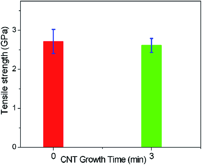 | ||
| Fig. 4 Single fiber tensile strength of CF versus CNT growth time. | ||
3.3 Interfacial properties of hierarchical CNTs/CF fiber and epoxy matrix
Epoxy is a most common matrix material for CFRPs, so the affinity of the CFs grafted with CNTs to epoxy was studied. When a micro-drop of epoxy resin is directly applied on a single CF, a contact angle of 78° is observed (Fig. 5a) which is very close to 77°,31 but higher than 52° as reported by others.17 The presence of CNTs on CF lowers the contact angle from 78° to 38° (Fig. 5b), which is close to 32° for entangled CNTs growing on CFs,17 indicating that the CNT forest improves the affinity of CF to epoxy. It is believed that the porous CNT forest increases the diffusion of epoxy to the CF. In fact, a CNT sponge with a similar entangled nanotube structure by CVD exhibits good performance as absorbents for many kinds of organic liquids including oils.32 Also, other oxygen-containing functional groups on CNTs (e.g., carboxyl functional group) during the flame synthesis21–23 can readily establish hydrogen bonding with epoxy. Thus, the affinity of CNTs/CF to epoxy is effectively increased, and the method to synthesize CNTs can be easily combined with other advanced fabrication techniques for CFRPs, e.g., vacuum-assisted resin transfer molding. | ||
| Fig. 5 Optical images of contact angles with micro-droplets of epoxy for (a) CF and (b) CF grafted with CNT grown for 3 minutes. | ||
A typical pull-out load versus displacement record of the single fiber test for CF grafted with CNTs for 3 minutes is shown in Fig. 6a, where the load increases linearly with displacement to the peak load, after which a sudden drop to zero ensues due to the instantaneous debonding of the fiber–matrix interface. Similar pull-out behavior is also observed for the bare CFs embedded in epoxy resin, which agrees with our previous work.26 In these tests, no detectable post-debond frictional fiber pull-out can be observed. Fig. 6b shows the maximum debond load versus embedded area of bare CF and CF grafted with CNTs grown for 3 min, where their corresponding IFSS values are obtained as the slopes of the least squares straight lines. The IFSS of CF/CNTs-3 min is ∼71% higher than the bare CF (Fig. 6c). This increase is slightly higher than that (57%) obtained on CF grafted with CNTs by CVD at 750 °C for 1 h (ref. 18) and close to that (77%) achieved by CVD growth of entangled CNTs on CFs at 800 °C for 0.5 h.15 Recent reports on the effect of in situ growth of CNTs on CF on their IFSS are given in Table 1. Clearly, despite the short-time to grow CNTs (only 3 minutes) on CFs using the present flame method, the improvement on IFSS is comparable to most CVD methods which always require more than ten-fold times for CNT growth. Note that although the high temperature during the flame growth process will damage the commercial sizing applied on carbon fibers, the CNT grafted CFs show much improved interfacial properties with epoxy, which indicates the advantage of our method through direct growth of CNTs on carbon fibers.
 | ||
| Fig. 6 (a) Typical pull-out load–displacement record. (b) Maximum debond force versus embedded area of CF with CNTs grown for 3 minutes and without CNTs. (c) Interfacial shear strength (IFSS) of CF versus CNT growth time. | ||
Since the length of CNTs can be controlled by adjusting the growth time, it is expected that the IFSS also depends on this factor. Hence, for CFs modified with CNTs synthesized for 1 min, the IFSS is only increased by ∼15% (Fig. 6c). This may be due to the shorter length of CNTs derived from the shorter growth time (<500 nm for 1 min growth and 1–2 μm for 3 min growth). This effect can be explained by the numerical simulated results of CNT length on crack bridging during the pullout of CFs covered with CNTs.33 Thus, longer CNTs impart higher IFSS. Supporting evidence is found from recent single fiber pull-out tests conducted on carbon fiber/polyester composites34 regarding the effect of CNT length on the IFSS of CNT modified CFs by CVD. It is also shown that the mode I interlaminar toughness of FRPCs is enhanced by increasing the length of CNTs grafted on alumina fabrics by CVD.35
Microscopy images of pulled out fiber surfaces indicate improved interfacial adhesion between fiber and matrix after the CFs are deposited with flame synthesized CNTs. Fig. 7a shows optical images of the matrix after fiber pull-out, displaying some black particles along the socket wall, which, at higher magnification with SEM imaging, illustrates pull-out of some CNTs from epoxy matrix (highlighted by red arrows in Fig. 7b). Some pulled out CNTs can be found resting on the CF surface (Fig. 7c) and some white dots may be caused by the CNTs broken at their roots (Fig. 7c). By contrast, the bare CF sample shows clean surfaces after the pull-out test (Fig. 7d).
 | ||
| Fig. 7 (a) Optical and (b) SEM images of the epoxy matrix socket and inside surface of the matrix socket, respectively, after single fiber pull-out of a CF/CNT-3 minutes. Fiber surfaces of (c) CF/CNT-3 minutes and (d) bare CF after single fiber pull-out tests. | ||
Only a few studies have been reported to identify the interfacial bonding of in situ grown CNTs on CFs,19,20 and the metal catalysts are thought to play an important role in the bonding process.17–19,36 The strong adhesion between CF substrate and CNTs may be due to the formation of the Ni@C core/shell structure and/or diffusion of metal catalyst particles into CF substrate in the initial stage of flame synthesized CNTs. The interface can be bridged by the formation of some C–C bonds between the carbon shell of the core/shell particles and the graphitic layers of CF surface,20 and/or by in situ formed Ni catalyst in the first stage of CNT growth according to the aforementioned flame growth mechanisms. Such an interface is highlighted by the red arrow in Fig. 2b, where the graphene layers extend from the carbon shell to the CF surface. This may lead to thicker roots than other parts of the CNTs (Fig. 2f). The diffusion of metal catalyst into CF during the growth of CNTs by CVD has been well-documented in the literature.17,18,36 For example, it is shown that Fe catalyst diffuses into CF substrate during the deposition of CNTs on CFs by CVD.17,18 The catalyst diffusion and partial embedding in CF substrate can also be clearly observed in our flame growth process, as displayed in Fig. 2b and c.
3.4 Electrical conductivity of CNTs modified CFRPs
The carbon fabrics employed in this study are unidirectional such that the electrical conductivities of the composite laminate are different in the three Cartesian directions (see Fig. 8a). The in-plane (x- or y-direction) electrical conductivities were measured to be one or two orders of magnitude higher than that in the out-of-plane (through-thickness z-direction) as displayed in Fig. 8b–d. Even in the in-plane direction of the fabric, the electric conductivity along the fiber x-direction is nearly 10-fold of that perpendicular to the fiber y-direction. As illustrated in Fig. 8a, the conductivity in the x-direction depends on the conductivity of carbon fibers themselves in their longitudinal direction, leading to the conductivity in x-direction highest among all directions. This huge difference mainly results from the laminated structure of the composite and the unidirectional nature of the carbon fabrics. The carbon fibers in the fabrics are actually in the form of fiber bundles. Some fibers, especially those in the outer parts of fiber bundles, are often wavy. These wavy fibers in turn provide many contact points between nearby fibers. Thus, different to the electrical conductivity in the x-direction, a complex 3D network of conduction paths formed via fiber to fiber contact through the insulating epoxy matrix,38–40 contributing to the electrical conductivity in the y- and z-directions. Contrary to the in-plane direction, the electrical insulating epoxy-rich area is mainly located within the interlayer between the CF fabrics, resulting in fewer conducting paths in the z-direction than those in the y-direction.39,40 Also, the exposed fibers on the sides in the y-direction are far more than those in the z-direction due to the hand lay-up structure. Together, all these factors yield much lower electrical conductivity in the z-direction. Compared to the control composite laminate, after the deposition of CNTs on CF fabrics, the in-plane electrical conductivities in x- and y-directions are increased by over 70% and 170%, respectively (Fig. 8b–c), while the out-of-plane conductivity in z-direction is increased by 44% (Fig. 8d). This is in part attributed to the different carbon fabric architecture. But more importantly, the improved electrical conductivity is a direct result of the formation of electrically conductive networks of the CNT porous layer on and between CFs in the fabrics in the limited interlayer area of the laminate (Fig. 8a). These enhanced in-plane conductivities are significant when compared to ∼37% increase for MWCNTs by electrophoretic deposition,37 ∼49% increase for MWCNTs by freeze drying,10 20% for carbon nanofibers by electrospinning and carbonization41 and ∼30% for anodic electrophoretic deposit of graphene sheets,31 but are less than the 330% for CNTs by PTCVD.25 It is noted that in our work, the increased conductivity in the x-direction is not as much as that in the y-direction due to the different contributions of CNTs in these two directions. In the x-direction, the continuous carbon fibers play a dominant role in electrical conductivity, and the increased electrical conductivity mainly originate from the additional electrical conducting path formed by the CNTs. In the y-direction of the laminates, where the conducting paths formed by nearby fibers dominate the electrical conductivity, the CNTs grafted on the fabric surface not only provide extra conductive networks but also serve as electrical bridges between CF fibers, leading to higher improvement in conductivity. | ||
| Fig. 8 (a) Schematic of CNT modified CFRP laminate showing anisotropy in three axes. Electrical conductivities of composite laminates fabricated with CF and CF/CNT reinforcements for (b) in-plane x-direction and (c) in-plane y-direction; and (d) out-of-plane z-direction. | ||
Although the enhanced electrical conductivity in the out-of-plane z-direction (44%) is comparable to that for electrophoresis deposition of MWCNTs (31%),7 it is much less than those in the in-plane x- and y-directions. The conductivity improvement in this through-thickness direction is notably less than that of 150% for carbon nanofibers,41 160% for MWCNTs,10 510% for CNTs deposited by PTCVD25 and 1500% for CNTs deposited by cathodic electrophoresis.37 The main reason is, in our work, that the CNTs are only deposited on one side of the carbon fabrics facing the flame, leaving the other side of the fabric with few CNTs. When the two plies with the CNT deposit side are laminated face to face as shown in Fig. 8a, only the interlayer area is reinforced with CNTs, while the outer sides of the plies change little relative to the bare CF fabrics. Thus, there is much less conductivity improvement in the out-of-plane direction. Nonetheless, the obtained results confirm that the CNTs deposited by in situ flame growth on the carbon fabrics can be controlled and used in CFRPs for simultaneous enhancements of interlaminar toughness and crack/damage sensing. These aspects will be reported in future publications.
4. Conclusions
In situ growth of CNTs on carbon fabric by flame synthesis was shown to be an efficient technique to develop hierarchical reinforcements in multi-scale laminated composites, which in turn improved the electrical conductivity and the interfacial shear strength. The ethanol flame temperature could be as low as 450 °C and there was no evident degradation of tensile strength of single carbon fibers after CNT deposition for 3 minutes. Both root and tip CNT growth mechanisms were observed in the flame process, but most CNTs were synthesized according to the root growth mode. Electrical conductivity improvements of 170% and 70% transverse to and along the fiber directions, respectively, and 44% in the through-thickness direction were achieved due to the flame synthesized CNTs anchored on the CFs. The IFSS was found to increase by ∼70% due to the good adhesion between CNTs and CFs arising from their carbon–carbon bonding and/or the diffusion of Ni catalyst particles into the CF substrate in the initial growth stage.Acknowledgements
We thank the Australian Research Council (ARC) for supporting this work through a Discovery Project (# DP130104648) at the University of Sydney.References
- H. Qian, E. S. Greenhalgh, M. S. P. Shaffer and A. Bismarck, J. Mater. Chem., 2010, 20, 4751–4762 RSC.
- S. U. Khan and J. K. Kim, Int. J. Aeronaut. Space Sci., 2011, 12, 93–111 Search PubMed.
- V. P. Veedu, A. Cao, X. Li, K. Ma, C. Soldano and S. Kar, Nat. Mater., 2006, 5, 457–462 CrossRef CAS PubMed.
- Y. Li, N. Hori, M. Arai, N. Hu, Y. Liu and H. Fukunaga, Compos Part A., 2009, 40, 2004–2012 CrossRef.
- M. Arai, N. Yukihiro, K.-I. Sugimoto and M. Endo, Compos. Sci. Technol., 2008, 68, 516–525 CrossRef CAS.
- E. J. Garcia, B. L. Wardle and A. J. Hart, Compos Part A., 2008, 39, 1065–1070 CrossRef.
- E. Bekyarova, E. T. Thostenson, A. Yu, H. Kim, J. Gao and J. Tang, Langmuir, 2007, 23, 3970–3974 CrossRef CAS PubMed.
- L. Dong, F. Hou, Y. Li, L. Wang, H. Gao and Y. Tang, Compos Part A., 2014, 56, 248–255 CrossRef CAS.
- L. Dong, Y. Li, L. Wang, Z. Wan, F. Hou and J. Liu, J. Mater. Sci., 2014, 49, 4979–4988 CrossRef CAS.
- L. Dong, Y. Li, L. Wang, F. Hou and J. Liu, Mater. Lett., 2014, 130, 292–295 CrossRef CAS.
- Q. Peng, X. He, Y. Li, C. Wang, R. Wang and P. A. Hu, J. Mater. Chem., 2012, 22, 5928–5931 RSC.
- E. T. Thostenson, W. Z. Li, D. Z. Wang, Z. F. Ren and T. W. Chou, J. Appl. Phys., 2002, 91, 6034–6037 CrossRef CAS.
- W. Fan, Y. Wang, J. Chen, Y. Yuan, A. Li, Q. Wang and C. Wang, RSC Adv., 2015, 5, 75735–75745 RSC.
- J. Zhao, L. Liu, Q. G. Guo, J. L. Shi, G. T. Zhai and J. R. Song, Carbon, 2008, 46, 380–383 CrossRef CAS.
- R. J. Sager, P. J. Klein, D. C. Lagoudas, Q. Zhang, J. Liu and L. Dai, Compos. Sci. Technol., 2009, 69, 898–904 CrossRef CAS.
- K. H. Hung, W. S. Kuo, T. H. Ko, S. S. Tzeng and C. F. Yan, Compos Part A., 2009, 40, 1299–1304 CrossRef.
- P. Lv, Y. Y. Feng, P. Zhang, H. M. Chen, N. Q. Zhao and W. Feng, Carbon, 2011, 49, 4665–4673 CrossRef CAS.
- H. Qian, A. Bismarck, E. S. Greenhalgh, G. Kalinka and M. S. P. Shaffer, Chem. Mater., 2008, 20, 1862–1869 CrossRef CAS.
- C. Wang, Y. Li, L. Tong, Q. Song, K. Li and J. Li, Carbon, 2014, 69, 239–246 CrossRef CAS.
- X. Du, H.-Y. Liu, C. F. Zhou, S. Moody and Y.-W. Mai, Carbon, 2012, 50, 2347–2350 CrossRef CAS.
- L. Liao, X. Wang, P. Fang, K. M. Liew and C. Pan, ACS Appl. Mater. Interfaces, 2011, 3, 534–538 CAS.
- X. Wang, H. Liu, P. Fang, L. Liao, C. Pan and K. M. Liew, J. Nanosci. Nanotechnol., 2010, 10, 948–955 CrossRef CAS PubMed.
- X. Du, H.-Y. Liu, F. Xu, Y. Zeng and Y.-W. Mai, Compos. Sci. Technol., 2014, 101, 159–166 CrossRef CAS.
- H. Qian, A. Bismarck, E. S. Greenhalgh and M. S. P. Shaffer, Compos Part A., 2010, 41, 1107–1114 CrossRef.
- T. R. Pozegic, I. Hamerton, J. V. Anguita, W. Tang, P. Ballocchi and P. Jenkins, Carbon, 2014, 74, 319–328 CrossRef CAS.
- S. Q. Deng, L. Ye and Y.-W. Mai, Adv. Compos. Mater., 1998, 7, 169–182 CrossRef CAS.
- C. M. Hsu, C. H. Lin, H. J. Lai and C. T. Kuo, Thin Solid Films, 2005, 471, 140–144 CrossRef CAS.
- M. Khosravi and M. K. Amini, Carbon, 2010, 48, 3131–3138 CrossRef CAS.
- Y. M. Chen, Z. G. Lu, L. M. Zhou, Y.-W. Mai and H. T. Huang, Energy Environ. Sci., 2012, 5, 7898–7902 CAS.
- Y. M. Chen, X. Y. Li, K. S. Park, J. Song, J. H. Hong and L. M. Zhou, et al., J. Am. Chem. Soc., 2013, 135, 16280–16283 CrossRef CAS PubMed.
- W. Lee, J. U. Lee, H.-J. Cha and J.-H. Byun, RSC Adv., 2013, 3, 25609–25613 RSC.
- X. Gui, J. Wei, K. Wang, A. Y. Cao, H. W. Zhu and Y. Jia, Adv. Mater., 2010, 22, 617–621 CrossRef CAS PubMed.
- Y. Jia, Z. R. Chen and W. Y. Yan, Compos. Sci. Technol., 2014, 91, 38–44 CrossRef CAS.
- P. Agnihotri, S. Basu and K. K. Kar, Carbon, 2011, 49, 3098–3106 CrossRef CAS.
- S. S. Wicks, R. G. de Villoria and B. L. Wardle, Compos. Sci. Technol., 2010, 70, 20–28 CrossRef CAS.
- K. J. Kim, W.-R. Yu, J. H. Youk and J. Lee, Phys. Chem. Chem. Phys., 2012, 14, 14041–14048 RSC.
- S.-B. Lee, O. Choi, W. Lee, J.-W. Yi, B.-S. Kim and J.-H. Byun, Compos Part A., 2011, 42(4), 337–344 CrossRef.
- N. Angelidis, C. Y. Wei and P. E. Irving, Compos Part A., 2006, 37, 1495–1499 CrossRef.
- Y. Hirano, T. Yamane and A. Todoroki, Compos. Sci. Technol., 2016, 122, 67–72 CrossRef CAS.
- A. Todoroki, M. Tanaka and Y. Shimamura, Compos. Sci. Technol., 2002, 62, 619–628 CAS.
- Q. Chen, L. Zhang, A. Rahman, Z. Zhou, X. F. Wu and H. Fong, Compos Part A., 2011, 42, 2036–2042 Search PubMed.
| This journal is © The Royal Society of Chemistry 2016 |