Extremely stretchable conductors based on hierarchically-structured metal nanowire network

Kang-Hyun Kim a, Dong-Wook Jeonga, Nam-Su Janga, Sung-Hun Haa and Jong-Man Kim*ab
aDepartment of Nano Fusion Technology and BK21 Plus Nano Convergence Technology Division, Pusan National University, Busan 46241, Republic of Korea
bDepartment of Nanoenergy Engineering, Pusan National University, Busan 46241, Republic of Korea. E-mail: jongkim@pusan.ac.kr

Received 14th April 2016 , Accepted 6th June 2016

First published on 7th June 2016


Abstract

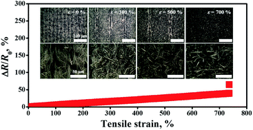
Giant stretchability of an elastic conductor can potentially extend its application scope in the emerging field of stretchable electronics. We present a new class of extremely stretchable conductors based on a hierarchically-structured (HS) metal nanowire network that can be simply fabricated by a prestraining technique with a micro-prism-arrayed elastomeric substrate. The unique architecture of the HS conductor with aligned metal nanowires on a sloped surface of a micro-prism structure makes it possible to achieve ultra-stretchability of higher than 700% while ensuring electrical and mechanical robustness. The HS stretchable conductor shows highly stable and reversible electrical performance even under high (∼750%) and repetitive (100 cycle) strains.

Introduction

A new class of electrical conductors with sufficient levels of stretchability have become key building blocks for the emerging field of flexible and stretchable electronics. Recently, conductive nanomaterial-based stretchable conductors have been widely employed as electrodes and interconnects in various stretchable devices.1–21 Examples include light-emitting diodes (LEDs),1–4 capacitive sensors,5–9 supercapacitors,10–13 semiconductor transistors,14–16 electrochromic devices,17,18 and radio frequency antennas.19–21 Among a variety of low-dimensional conductive materials, to date, metallic1–3,9,15–17,19,20,28,31 and carbon-based nanomaterials4–8,10–14,18,23–26,29,32 have been widely used to build percolation conductive pathways in the form of random1–7,9–12,14–20,26,28,31,32 and aligned networks.8,13,23–25,29 This is mainly attributed to the superior electrical properties and easy processability of metallic and carbon-based percolation conductive networks (PCNs).

Several different architectures for stretchable conductors have been demonstrated by integrating PCNs with various shapes of elastomeric substrates. The most straightforward way of realizing PCN-based stretchable conductors is to transfer PCNs onto simple elastomeric substrates.3–9,13–18,20,23,29 However, these conductors typically exhibit a relatively low stretching limit because the electrical performance of devices depends only on the intrinsic morphologies of the PCNs. Compared to simple architectures, buckled structures of PCNs are highly desirable for improving the stretchability of devices while ensuring simple fabrication.2,10–12,19,24,25 Buckled structures can be formed easily by transferring PCNs onto pre-deformed elastomeric substrates and subsequently releasing pre-deformations. PCNs have also been combined with unique architectures of elastomers to produce high-performance stretchable conductors, such as fibers,1,30 microfluidic channels,21,22 three-dimensional (3-D) forms,26–28 helical structures,31 and kirigami-patterned substrates.32

To meet the ongoing demand for high-performance stretchable electronics, elastic conductors with giant stretchability of over 300% have recently been developed.1,2,8,22,27,29–32 Liquid-phase metal alloy filled into enclosed stretchable platforms such as microfluidic channels,22 3-D forms,27 and hollow fibers30 is more desirable for retaining electrical performance upon stretching compared to PCNs made of solid nanomaterials. However, possible leakage of liquid metal might severely and irreversibly degrade the electrical performance of the devices. In addition, cumbersome fabrication is likely to be a major obstacle in developing practical stretchable devices. Robust architectures of high aspect ratio conductive nanomaterials such as very long metal nanowires2 and vertically-aligned carbon nanotube forests8,29 can play an important role in improving the stretchability of the resulting devices. Nevertheless, a critically specific and complicated synthesis process should be required. Substrate designs that can be robust to large deformations have been integrated with typical PCNs to systematically alleviate stretching limits.1,31,32 Although several elastomer designs including hollow fibers,1 helical springs,31 and defected sheets32 have been introduced, the overall fabrication is very complex and cumbersome.

In this work, we present a new class of extremely stretchable conductors made of a hierarchically-structured (HS) metal nanowire percolation network that is prepared by using a simple prestraining method with a periodically micro-prism-structured elastomeric substrate. The proposed unique HS surface morphology makes it possible to achieve ultra-stretchability of higher than 700% while ensuring electrical and mechanical robustness.

Experimental

Synthesis of AgNWs

AgNWs were synthesized by using a CuCl2-mediated polyol process.33 10 mL of ethylene glycol (EG) (Daejung Chemical & Metal) were placed in a 160 °C heated oil bath that was magnetically stirred at 360 rpm for 1 h. Then, 40 μL of copper(II) chloride (CuCl2) (4 mM, Samchun Chemical) were added to the EG solution. After 15 min, 3 mL of 0.3 M polyvinyl pyrrolidone (PVP) (Alfa Aesar) in EG and 3 mL of 0.1 M silver nitrate (AgNO3) (Sigma-Aldrich) in EG were injected simultaneously into the EG solution at a fixed injection rate of 0.3 mL min−1 using a commercially available two-channel syringe pump (Legato 111, KD Scientific). The mixture was heated at 160 °C and stirred at 360 rpm for 1 h, followed by centrifugation at 2000 rpm for 20 min using a centrifuge (TD4Z-WS, Nasco Korea) to purify the synthesized AgNWs. The purification process was carried out in a mixture of acetone and ethanol (1[thin space (1/6-em)]:[thin space (1/6-em)]1 by volume) and repeated at least three times. The AgNW solution for the spray coating was prepared by dispersing the purified AgNWs in ethanol at a fixed concentration of 20 mg mL−1.

Fabrication of stretchable conductors

Surface structure of HS stretchable conductor was formed by a simple combination of a prestraining method based on a micro-prism-arrayed elastomeric substrate and spray deposition of AgNWs. A micro-prism-arrayed elastomeric substrate was prepared by an Ecoflex replication process. Prior to this, a micro-mold substrate was fabricated by an anisotropic chemical etching of silicon. For this, a 300 nm-thick silicon oxide (SiO2) etching mask was formed by etching SiO2 selectively using a buffered oxide etch (BOE) solution with a photolithographically defined photoresist (PR) etching mask. A silicon etching process was then carried out using a 20 wt% tetramethylammonium hydroxide (TMAH) solution in a double-walled beaker connected to a circulator (RW-1025G, Jeio Tech) at 80 °C. Finally, the SiO2 etching mask was completely removed by the BOE solution. The fabricated micro-prism array showed a prism height of ∼30 μm and inter-prism distance (peak-to-peak) of ∼50 μm.

Ecoflex prepolymer (0010, Smooth-On) and a curing agent were mixed at a weight ratio of 1[thin space (1/6-em)]:[thin space (1/6-em)]1 and stirred for 10 min for complete mixing. After placing the mixture in a vacuum desiccator for 1 h to completely remove air bubbles, the mixture was poured onto the silicon micro-mold and solidified by thermal curing at 70 °C for 30 min in a convection oven. The micro-prism-structured Ecoflex substrate was prepared by peeling it off from the silicon mold.

The AgNW solution was sprayed onto a micro-prism-arrayed Ecoflex substrate that was prestrained (300%) using a custom-made mechanical jig. The coating process was carried out using a commercially available airbrush (DH-125, Sparmax) with a nozzle diameter of 1 mm. During the coating, the prestrained Ecoflex substrate was placed on a hotplate at 80 °C to evaporate the solvent components. No further thermal annealing was conducted on the deposited AgNW network. The surface structure of HS stretchable conductor was finally formed by carefully releasing the prestrain from the elastomeric substrate.

Nano-structured (NS) surface morphology was prepared by spraying AgNWs onto a prestrained (300%) flat Ecoflex substrate. After releasing the prestrain, the coated AgNWs were structured by being aligned perpendicular to the released direction, while clearly exhibiting different morphology with the as-coated one. Micro-structured (MS) surface morphology was prepared by just spraying AgNWs onto a micro-prism-arrayed Ecoflex substrate without prestraining. Therefore, AgNW percolation network is formed along to the surface shape of the micro-prism array on the elastomeric substrate, while maintaining the as-coated morphology.

Characterization

The surface morphology of the fabricated conductor was investigated using an optical microscope (OM) (BX60M, Olympus) and a field emission scanning electron microscope (FESEM) (S7400, Hitachi). Cross-sectional profiles of as-prepared (ε = 0%) and prestrained (ε = 300%) micro-prism-arrayed Ecoflex substrates were measured by using a non-contact 3-D profiler (NV-1000, Nanosystem).

The stretching test was performed by using a commercially available motorized stage (JSV-H100, JISC) equipped with a push–pull force gauge (HF-10, JISC) while measuring the electrical resistance with a digital multimeter (U1253B, Agilent Technologies) in real time. Prior to the stretching test, electrical wires were connected to both ends of the stretchable conductor and covered with Ecoflex.

Results and discussion

Fig. 1 shows the fabrication sequence of the proposed HS stretchable conductor. Easy fabrication is readily achievable because the process is based on a simple and widely used prestraining method, wherein a flat elastomeric substrate is replaced with a micro-structured substrate. First, a sufficient prestrain is applied to the micro-prism-structured Ecoflex substrate so that slope length (lm) of the micro-prism can be increased to lm + Δlm. When releasing the prestrain after AgNW coating, the AgNWs connected to each other can slide and rotate simultaneously around a contact junction (see top-view illustrations in Fig. 1) during a physical restoration of the elastomeric substrate. This leads to a nanoscale structuring of the AgNW network by allowing the AgNWs to be aligned on the surface of the micro-prism-structured elastomer.
image file: c6ra09644a-f1.tif
Fig. 1 Schematic illustration of fabrication sequence of HS stretchable conductor based on prestraining technique with micro-prism-arrayed elastomeric substrate.

This results in the formation of an HS AgNW network with both nano-structured (NS) and micro-structured (MS) morphologies.

Fig. 2 shows SEM images of the fabricated AgNW-networked stretchable conductors with different surface morphologies. Fig. 2(a) shows the AgNW network formed on a flat Ecoflex substrate, which represents a very uniform distribution. After releasing the prestrain applied to the flat substrate, the AgNWs were aligned perpendicular to the released direction, as shown in Fig. 2(b). This suggests that the AgNWs slid and predominantly rotated around the contact junctions. This is probably attributed to the fact that the AgNWs are not welded to each other at the contact junctions because no post-annealing processes were conducted. The aligned morphology of the AgNWs was also found on the surface of the micro-prism array of the HS conductor, as compared in Fig. 2(c) and (d). This morphology originates from the fact that the slope surface of the Ecoflex micro-prism structure is sufficiently stretched by applying a prestrain of 300%, as compared in digital images and cross-sectional profiles of the as-prepared (ε = 0%) and prestrained (ε = 300%) substrates in Fig. 3(a) and (b). Therefore, AgNWs sprayed onto the stretched slope surface of the Ecoflex micro-prism can also experience a slide and rotation around the contact junctions upon releasing. This implies that the stretchability of the HS conductor can potentially be controlled by modulating the period of the microscale surface structures and prestrain levels according to the particular application.


image file: c6ra09644a-f2.tif
Fig. 2 Fabrication results of AgNW-networked stretchable conductors with different surface morphologies. SEM images of (a) flat, (b) nanoscale single-structured (NS), (c) microscale single-structured (MS), and (d) HS conductors (scale bars: 50 μm; inset in (c) and (d) enlarged top-view SEM image (scale bars: 20 μm)).

image file: c6ra09644a-f3.tif
Fig. 3 Fabrication results of micro-prism-arrayed elastomeric substrate. Digital images (top and cross-sectional views) and cross-sectional profiles of (a) as-prepared (ε = 0%) and (b) prestrained (ε = 300%) substrates. Note: scale bars represent 50 μm.

The electrical performance of the AgNW-networked stretchable conductors was characterized by measuring the change in the electrical resistance (ΔR/R0) according to applied tensile strain. Fig. 4(a) shows ΔR/R0 for devices with various surface morphologies. The maximum strain (εmax) that can maintain the electrical performance without failure and ΔR/R0 at εmax are summarized in Fig. 4(b). The flat conductor withstood a tensile strain of up to ∼131.3% without electrical failure, showing a ΔR/R0 value of ∼32.6%. After structuring the AgNW network at the microscale (MS conductor) and nanoscale (NS conductor), εmax was improved to ∼348.2% and ∼525.8% without a considerable resistance increase, respectively (ΔR/R0 at εmax = ∼33.5% for the MS conductor and ∼39.2% for the NS conductor). With a simple combination of the MS and NS morphologies, the HS stretchable conductor could be stretched to over 730%. Importantly, ΔR/R0 was found to be only ∼39.4% at εmax. This is mainly attributed to the unique hierarchical morphology that can make the AgNW network much more robust to tensile strain during a stretch.


image file: c6ra09644a-f4.tif
Fig. 4 Electrical characterization. (a) Resistance change ratio (ΔR/R0) (inset: digital image of the HS conductor stretched to ∼730%) and (b) maximum strain (εmax) and ΔR/R0 at εmax of AgNW-networked stretchable conductors with different surface morphologies.

Fig. 5(a) shows top-view optical microscope images of the HS conductor under various strains. AgNWs that were aligned perpendicular to the released direction by a prestraining effect almost returned to the as-coated morphology when the device was stretched to the prestrained level (300%). As the strain was increased beyond 300%, the AgNWs gradually realigned to the strained direction. Nevertheless, it was found that many of the contact junctions among the individual AgNWs were still maintained up to 700% strain, as shown in Fig. 5(a).


image file: c6ra09644a-f5.tif
Fig. 5 HS stretchable conductor under stretching. (a) Top-view optical microscope images of device under various strains (scale bars: 200 μm (upper), 50 μm (lower)), and (b) schematic illustration of a working principle of HS conductor upon stretching.

The giant stretchability of the HS conductor can be explained by using a simple model for the sequential change of the surface morphology, as shown in Fig. 5(b). The AgNWs on the HS conductor are initially aligned by being slid and rotated simultaneously around the contact junctions during a prestraining process ((i) ε = ε0). In response to the applied tensile strain (ε), a microscale surface structure of the device is flattened predominantly along the strained direction. This suggests that a sloped surface of the micro-prism structure is less stretched compared to the flat conductor. Therefore, the aligned morphology of the AgNW network on the sloped surface can be almost retained up to a certain level of strain ((ii) ε = ε1 > ε0), resulting in little change in ΔR/R0. When increasing tensile strain to the prestrained level ((iii) ε = ε2 > ε1), the sloped surface of the micro-prism structure is gradually stretched. However, the AgNW percolation network on the HS conductor is still well maintained, representing a much smaller resistance change than the MS conductor, as shown in Fig. 4(a). This is because the AgNW network on the HS conductor becomes similar to the as-coated morphology due to the prestraining effect. It is for this reason that the HS conductor shows superior stretchability compared to the MS conductor because contact junctions between AgNWs on the sloped surface of the MS conductor are more easily lost even under the same strain. With increasing tensile strain ((iv) ε = ε3 > ε2), the AgNWs start to realign toward the strained direction. Compared to the NS conductor, the AgNW percolation network on the HS conductor is more physically robust to tensile strain because the sloped surface of the micro-prism structure is less stretched than flat surface, even if the same level of strain is applied to the devices. This means that fewer contact junctions between AgNWs are broken on the sloped surface than the flat surface upon stretching. This also makes it possible to obtain a smaller value of ΔR/R0 for the HS conductor by more adequately suppressing the morphological change of the AgNW network (rather than the NS conductor) during a stretch. Therefore, we suggest that the unique HS architecture is very helpful in achieving high stretchability and high electrical performance of elastic conductors in a simple manner.

In addition to high stretchability, electrical robustness against repetitive deformation is also one of the most important requirements in developing elastic conductors in practical stretchable electronics applications. To check this, the electrical performance of an HS conductor with εmax = ∼750% and ΔR/R0 at εmax = ∼43.3% was characterized for 100 stretching cycles under a strain of 750%, as shown in Fig. 6(a). The ΔR/R0 of the device was measured to be ∼43.2 ± 0.09% and ∼0.15 ± 0.07% in each stretched (ε = 750%) and returned state (ε = 0%), respectively, as shown in Fig. 6(b) and (c), respectively. Significant changes in the electrical performance and physical damage were not found on the HS conductor even after a number of cycles of stretching. This clearly shows that the HS conductor can be operated stably and reversibly, even under high and repetitive strains.


image file: c6ra09644a-f6.tif
Fig. 6 Electrical performance of HS conductor under cyclic stretching. (a) ΔR/R0 according to repetitive stretching with a maximum tensile strain of 750%, and ΔR/R0 distributions measured for 100 stretching cycles in (b) stretched (ε = 750%) and (c) returned (ε = 0%) states.

Conclusions

In conclusion, a novel architecture for a hierarchically-structured AgNW-networked stretchable conductor was proposed and demonstrated. The two-level surface morphology of the AgNW network was readily fabricated by releasing a prestrained micro-prism-arrayed elastomeric substrate after a spray deposition of the AgNWs. The unique morphology of the HS conductor resulted in a giant stretchability of over 700% without severe degradation in electrical performance, which indicates ∼460.4, ∼111.3, and 39.9% improvement of the maximum strain compared to the flat, MS, and NS conductor, respectively. The HS stretchable conductor was highly stable and reversible even under repetitive deformation with a tensile strain of 750%, representing ΔR/R0 values of ∼43.2 ± 0.09% and ∼0.15 ± 0.07% in the stretched and returned states, respectively. We believe that the novel HS conductor can be integrated into various functional devices in order to build high-performance stretchable electronics.

Acknowledgements

This research was supported by the Basic Science Research Program (No. 2015R1A2A2A01004038) through the National Research Foundation of Korea (NRF) funded by the Ministry of Science, ICT & Future Planning.

Notes and references

  1. Y. Cheng, R. Wang, J. Sun and L. Gao, ACS Nano, 2015, 9, 3887 CrossRef CAS PubMed.
  2. P. Lee, J. Lee, H. Lee, J. Yeo, S. Hong, K. H. Nam, D. Lee, S. S. Lee and S. H. Ko, Adv. Mater., 2012, 24, 3326 CrossRef CAS PubMed.
  3. J. Liang, L. Li, X. Niu, Z. Yu and Q. Pei, Nat. Photonics, 2013, 7, 817 CrossRef CAS.
  4. T. Sekitani, H. Nakajima, H. Maeda, T. Fukushima, T. Aida, K. Hata and T. Someya, Nat. Mater., 2009, 8, 494 CrossRef CAS PubMed.
  5. S.-J. Woo, J.-H. Kong, D.-G. Kim and J.-M. Kim, J. Mater. Chem. C, 2014, 2, 4415 RSC.
  6. D. J. Cohen, D. Mitra, K. Peterson and M. M. Maharbiz, Nano Lett., 2012, 12, 1821 CrossRef CAS PubMed.
  7. D. J. Lipomi, M. Vosgueritchian, B. C.-K. Tee, S. L. Hellstrom, J. A. Lee, C. H. Fox and Z. Bao, Nat. Nanotechnol., 2011, 6, 788 CrossRef CAS PubMed.
  8. U.-H. Shin, D.-W. Jeong, S.-M. Park, S.-H. Kim, H. W. Lee and J.-M. Kim, Carbon, 2014, 80, 396 CrossRef CAS.
  9. F. Xu and Y. Zhu, Adv. Mater., 2012, 24, 5117 CrossRef CAS PubMed.
  10. X. Li, T. Gu and B. Wei, Nano Lett., 2012, 12, 6366 CrossRef CAS PubMed.
  11. J. Zang, C. Cao, Y. Feng, J. Liu and X. Zhao, Sci. Rep., 2014, 4, 6492 CrossRef CAS PubMed.
  12. C. Yu, C. Masarapu, J. Rong, B. Wei and H. Jiang, Adv. Mater., 2009, 21, 4793 CrossRef CAS PubMed.
  13. T. Chen, H. Peng, M. Durstock and L. Dai, Sci. Rep., 2014, 4, 3612 Search PubMed.
  14. M. Xia, Z. Cheng, J. Han and S. Zhang, Appl. Phys. Lett., 2014, 105, 143504 CrossRef.
  15. N. Matsuhisa, M. Kaltenbrunner, T. Yokota, H. Jinno, K. Kuribara, T. Sekitani and T. Someya, Sci. Rep., 2015, 6, 7461 CAS.
  16. M.-S. Lee, K. Lee, S.-Y. Kim, H. Lee, J. Park, K.-H. Choi, H.-K. Kim, D.-G. Kim, D.-Y. Lee, S. Nam and J.-U. Park, Nano Lett., 2013, 13, 2814 CrossRef CAS PubMed.
  17. C. Yan, W. Kang, J. Wang, M. Cui, X. Wang, C. Y. Foo, K. J. Chee and P. S. Lee, ACS Nano, 2014, 8, 316 CrossRef CAS PubMed.
  18. H.-H. Chou, A. Nguyen, A. Chortos, J. W. F. To, C. Lu, J. Mei, T. Kurosawa, W.-G. Bae, J. B.-H. Tok and Z. Bao, Sci. Rep., 2015, 6, 8011 CAS.
  19. B. S. Kim, K.-Y. Shin, J. B. Pyo, J. Lee, J. G. Son, S.-S. Lee and J. H. Park, ACS Appl. Mater. Interfaces, 2016, 8, 2582 CAS.
  20. L. Song, A. C. Myers, J. J. Adams and Y. Zhu, ACS Appl. Mater. Interfaces, 2014, 6, 4248 CAS.
  21. M. Kubo, X. Li, C. Kim, M. Hashimoto, B. J. Wiley, D. Ham and G. M. Whitesides, Adv. Mater., 2010, 22, 2749 CrossRef CAS PubMed.
  22. K. P. Mineart, Y. Lin, S. C. Desai, A. S. Krishnan, R. J. Spontak and M. D. Dickey, Soft Matter, 2013, 9, 7695 RSC.
  23. Y. Zhang, C. J. Sheehan, J. Zhai, G. Zou, H. Luo, J. Xiong, Y. T. Zhu and Q. X. Jia, Adv. Mater., 2010, 22, 3027 CrossRef CAS PubMed.
  24. U.-H. Shin, D.-W. Jeong, S.-H. Kim, H. W. Lee and J.-M. Kim, ACS Appl. Mater. Interfaces, 2014, 6, 12909 CAS.
  25. Y. Yu, S. Luo, L. Sun, Y. Wu, K. Jiang, Q. Li, J. Wang and S. Fan, Nanoscale, 2015, 7, 10178 RSC.
  26. S. Duan, K. Yang, Z. Wang, M. Chen, L. Zhang, H. Zhang and C. Li, ACS Appl. Mater. Interfaces, 2016, 8, 2187 CAS.
  27. J. Park, S. Wang, M. Li, C. Ahn, J. K. Hyun, D. S. Kim, D. K. Kim, J. A. Rogers, Y. Huang and S. Jeon, Sci. Rep., 2012, 3, 916 Search PubMed.
  28. J. Ge, H.-B. Yao, X. Wang, Y.-D. Ye, J.-L. Wang, Z.-Y. Wu, J.-W. Liu, F.-J. Fan, H.-L. Gao, C.-L. Zhang and S.-H. Yu, Angew. Chem., Int. Ed., 2013, 125, 1698 CrossRef.
  29. M. K. Shin, J. Oh, M. Lima, M. E. Kozlov, S. J. Kim and R. H. Baughman, Adv. Mater., 2010, 22, 2663 CrossRef CAS PubMed.
  30. S. Zhu, J.-H. So, R. Mays, S. Desai, W. R. Barnes, B. Pourdeyhimi and M. D. Dickey, Adv. Funct. Mater., 2013, 23, 2308 CrossRef CAS.
  31. Y. Won, A. Kim, W. Yang, S. Jeong and J. Moon, NPG Asia Mater., 2014, 6, e132 CrossRef CAS.
  32. T. C. Shyu, P. F. Damasceno, P. M. Dodd, A. Lamoureux, L. Xu, M. Shlian, M. Shtein, S. C. Glotzer and N. A. Kotov, Nat. Mater., 2015, 14, 785 CrossRef CAS PubMed.
  33. K. E. Korte, S. E. Skrabalak and Y. Xia, J. Mater. Chem., 2008, 18, 437 RSC.

Footnote

These authors contributed equally to this work.

This journal is © The Royal Society of Chemistry 2016
Click here to see how this site uses Cookies. View our privacy policy here.