Recent advances in melt electrospinning

Li-Hua Zhang ab, Xiao-Peng Duan a, Xu Yana, Miao Yuac, Xin Ningd, Yong Zhao *b and Yun-Ze Long *ad
aCollaborative Innovation Center for Nanomaterials & Optoelectronic Devices, College of Physics, Qingdao University, Qingdao 266071, China. E-mail: yunze.long@163.com; yunze.long@qdu.edu.cn
bSchool of Chemistry & Environment, Beihang University, Beijing 100191, China. E-mail: zhaoyong@buaa.edu.cn
cDepartment of Mechanical Engineering, Columbia University, NewYork, NY 10027, USA
dIndustrial Research Institute of Nonwovens & Technical Textiles, College of Textiles & Clothing, Qingdao University, Qingdao 266071, China

Received 13th April 2016 , Accepted 24th May 2016

First published on 26th May 2016


Abstract

With the emergence of one-dimensional (1D) functional nanomaterials and their promising applications, electrospinning (e-spinning) technology and electrospun (e-spun) ultrathin fibers have been widely explored. Melt e-spinning as an ecofriendly method which produces fibers from polymer melt has drawn much attention in recent years. Meanwhile, melt e-spun fibers without any residual solvent provide opportunities in many areas such as tissue engineering, wound dressings, filtration and textiles. In this review, we introduce the basic principles and recent developments of melt e-spinning, and then summarize various heating methods and various materials used in melt e-spinning, and the influence of several parameters. Particularly, several kinds of new melt e-spinning apparatuses (e.g., portable apparatus and apparatus for mass production), 3D fibrous structures and some applications developed recently are reviewed. Finally, we discuss the future prospects and challenges of melt e-spinning.
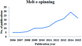

image file: c6ra09558e-p1.tif

Li-Hua Zhang

Li-Hua Zhang received her BS degree from Qingdao University in 2014. Now she is studying for a master's degree at Qingdao University (with Prof. Yun-Ze Long). At the same time, she receives united training by Beihang University (with Prof. Yong Zhao). Her current scientific interests are focused on melt electrospinning and electrospinning biomaterials.

image file: c6ra09558e-p2.tif

Xiao-Peng Duan

Xiao-Peng Duan received his BS degree from Qingdao University in 2014. Now he is studying for a master's degree at Qingdao University (with Prof. Yun-Ze Long). At the same time, he receives united training by Quanzhou Normal University (with Prof. Da-Peng Yang). His current scientific interests are focused on melt electrospinning and electrospinning biomaterials.

image file: c6ra09558e-p3.tif

Yong Zhao

Yong Zhao is currently a professor at the School of Chemistry and Environment, Beihang University. He received his Ph.D. from the Institute of Chemistry, Chinese Academy of Sciences (ICCAS), China in 2007 (with Prof. Lei Jiang). From 2007 to 2011, he worked at ICCAS as an assistant professor and associate professor. In 2011, he joined Beihang University as a professor. In 2016, he worked as a one-year visiting professor at Harvard University (with Prof. David A. Weitz). His current scientific interests are focused on electrospinning super-wetting nanofibrous materials for elastic electronics and biomaterials.

image file: c6ra09558e-p4.tif

Yun-Ze Long

Yun-Ze Long received his BS degree from the University of Science & Technology of China in 2000 and his PhD degree from the Institute of Physics, Chinese Academy of Sciences in 2005. Then he worked in the Institut des Materiaux Jean Rouxel, CNRS, France, as a postdoctoral Fellow. He has been with Qingdao University since Dec. 2006, where he is currently a full Professor. From 2009 to 2011, he worked as a visiting researcher in the University of Sydney and the Hong Kong University of Science & Technology. He has published more than 150 papers, and holds more than 40 China patents. His research interests are focused on electrospinning, functional nanomaterials and their applications in nanodevices and biomedicine.


1. Introduction

Micro-/nanoscale fibers have several amazing properties such as a high surface area to volume ratio, high porosity, flexibility in surface functionalities, extensive selection of polymer materials, etc.1–3 And these properties endow polymer fibers with many attractive applications such as biomedical materials, protective clothing, air filtration, liquid filters and separators, sensors, battery membranes etc.4–8 With the development of technology, more and more potential applications are predictable in various interdisciplinary domains. Table 1 lists different methods and their advantages and disadvantages for fabricating polymer fibers.9–18 In these methods, electrospinning (e-spinning), which usually contains solution e-spinning and melt e-spinning, is an important, broadly used method for fabricating ultrathin polymer fibers. Recently, researchers from all over the world have paid much attention in the improvement of e-spinning apparatus, morphology/structure control and the potential applications of electrospun (e-spun) fibers.
Table 1 Comparison of main processes producing micro-/nanofibers
Method Advantages Disadvantages Development stage References
Stretch spinning Long single fibers Suitable for narrow materials Industrialized 9
Electrospinning Mass fabrication of continuous polymer fibers, simple Usually in form of nonwoven, web; possible alignment Industrialized 10 and 11
Melt blown Continuous fibers Larger diameter, high temperature Industrialized 12
Bicomponent spinning High denier, ultrafine fiber, stability Suitable composition ratio, affected by spinneret Inclined to be industrialized 13
Template polymerization Suitable for different materials, wide range Short fibers, 1D-nanostructures Laboratory scale 14 and 15
Self-assembly Simple, without special equipment Time consuming, uncontrollable Laboratory scale 16 and 17
Phase separation Simple, without equipment requirement Time consuming Laboratory scale 18


Solution e-spinning is the most popular e-spinning technique by now, in which when solvent evaporates, left-behind polymer fibers are solidified and collected. Although solution e-spinning is an effective versatile technique to fabricate fibers with diameters ranging from micrometers to nanometers from a variety of polymer solutions, the major challenges for solution e-spinning are recovery of organic solvents, potential environmental pollution of solvent accumulation, residue of organic/toxic solvent in nanofibers, and small pores on the fibrous membrane.19,20 These drawbacks largely influence mass production and biomedical applications of e-spun nanofibers. In addition, solution e-spinning is unable to process nonsoluble polymers such as polypropylene (PP) and polyethylene (PE). Melt e-spinning is a good way to solve these problems. Table 2 shows the comparison between solution e-spinning and melt e-spinning.

Table 2 Comparison of solution e-spinning and melt e-spinning
Method Fiber diameter Main factor Advantages Disadvantages
Solution e-spinning Dozens to thousands nm Solution solubility, solution system properties, static, voltage, collection distance Inexpensive, simple device, easy operate Environmental pollution, solvent recovery
Melt e-spinning ≥500 nm, about 200 nm partially Melt viscosity, static voltage, ambient temperature Ecofriendly, safety, biomedical applications Complicated device, expensive, large diameter


The first scientific literature on melt e-spinning was published by Larrondo and St. John Manley in 1981,21 half a century later than the earliest description of melt e-spinning process in a patent approved in 1936 by Charles Norton from the Massachusetts Institute of Technology.22 The main cause of this phenomenon is that the experimental equipment for melt e-spinning is more complicated.23–25 And the second article on melt e-spinning was published in 2001, 20 years later by Reneker and Rangkupan.26 Until now, a total of about 150 articles that include the words “melt electrospinning” have been retrieved based on “Web of Science” at the beginning of 2016. Here, a survey of papers related to melt e-spinning in the past 10 years is given in Fig. 1. The number of open publications shows an increasing trend. However, the research papers on melt e-spinning are much less than solution e-spinning. The possible reasons include more complicated apparatus (needing a heating and temperature control system), relatively lager fiber diameter and less raw materials for melt e-spinning.


image file: c6ra09558e-f1.tif
Fig. 1 Comparison of the annual number of scientific publications related to “melt electrospinning” based on “Web of Science” since 2006.

Melt e-spinning has made rapid progress in the last 15 years. For instance, Xia et al.29 combined melt e-spinning with coaxial spinneret to provide a facile method for the encapsulation of solid materials and fabrication of phase change nanofibers. Ogata et al.30 introduced a line laser melt e-spinning to produce poly(ethylene-co-vinyl alcohol) (EVOH) and Nylon 6/12 nanofibers. The sub-micron fibers successfully fabricated in gas-assisted polymer melt e-spinning process by Joo and his cooperators.25 Lin et al.31 reported a needleless melt-electrospinning setup employing a disc spinneret was used to e-spin molten PP. Until now, dozens of polymers have been used to melt e-spinning,32 and the potential applications of melt-electrospun fibers in textiles, tissue engineering, filtration and biomedical areas have also been demonstrated.33–36

Here, a review is presented on the studies and developments related to melt e-spinning such as spinning mechanism, parameters, heating methods, materials, morphology, and applications. In addition, this review describes latest developments and challenges of melt e-spinning.

2. Mechanism of melt e-spinning

There are two kinds of e-spinning techniques: solution e-spinning and melt e-spinning. The designed melt e-spinning apparatus has been displayed in Fig. 2. Fig. 2a shows the components of melt e-spinning apparatus and Fig. 2b displays the schematic diagrams of melt e-spinning apparatus. Different from solution e-spinning apparatus which only has three components: a high voltage supply, a capillary tube with a pipette or needle of small diameter and a ground collector, melt e-spinning apparatus requires more complicated equipment, usually a higher spinning voltage and a heating system including temperature sensor.34,37 In the melt e-spinning process, one electrode connects to the spinning melt and the other connects to the metal collector. When the electrostatic forces overcome the surface tension of polymer melt, the discharged jet erupts and elongates in the electrostatic field, then cools down and deposits on the collector. Table 3 displays a list of different melt e-spinning apparatuses reported.
image file: c6ra09558e-f2.tif
Fig. 2 The designed melt e-spinning apparatus (MEA): (a) the components of MEA and (b) the schematic diagrams of MEA.
Table 3 List of melt e-spinning apparatus
Location of device Reported Heating HV Configuration Collector References
McGill University 1981 Electric Polymer Vertical Static/dynamic 21
University of Akron 2001 Radiant Polymer Unknown Static 38 and 39
Drexel University 2003 Electric Collector Horizontal Static 40 and 41
Cornell University 2006 Electric Polymer Horizontal Static 34, 42–46
2010 GAME Collector Horizontal Static 25
RWTH Aachen 2006 Circulating (water) Polymer Vertical Static/dynamic 47–50
2007 Heated air Polymer Horizontal Static/dynamic 48 and 51
2009 Electrical Polymer Vertical multi-nozzle Dynamic 52
University of Washington 2006 Electric Polymer Vertical Static 53
2011 Electric Collector Unknown Static 54
University of Fukui 2007 Laser Polymer Vertical Static/rotating 55–59
University of Southampton 2008 Circulating (water) Polymer Vertical Static 60
Virginia Polytechnic and State University 2008 Electric Collector Unknown Static 61
Yamagata University 2009 Electric Collector Vertical Static 62
Beijing University of Chemical Technology 2009 Electric Collector Horizontal Static 37
Islamic Azad University 2009 Circulating (oil) Unknown Vertical Static 63
Korea Maritime University 2009 Electric Polymer Vertical Static 64
Karpov Institute of Physical Chemistry and Fiber Materials 2009 Electric Collector Horizontal Static 65
Queensland University of Technology 2010 Circulating (water) Polymer Vertical Static/dynamic 66
Chungnam National University 2010 Circulating (oil) Collector Horizontal Rotating 67
2013 Circulating (oil) Collector Horizontal Rotating 68
Tongji University 2010 Circulating (water) Collector Vertical Static 69
Beijing Institute of Fashion Technology 2012 Laser Polymer Vertical Dynamic 70
Beijing University of Chemical Technology 2012 Electric Polymer Vertical Static 71
2014 Electric Polymer Vertical Static 72
Qingdao University 2015 Heat gun Polymer Vertical Static 73
2016 Heat gun Polymer Vertical Static 74


Melt e-spinning can fabricate ultrathin fibers with diameters ranging from micrometer scales to nanoscale. And the fiber diameters have been successfully controlled by changing parameters in melt e-spinning process. Submicron fibers have been obtained from various melt e-spinning configurations in different research groups. The smallest diameter melt e-spun polymers reported for non-mechanically drawn e-spun fibers was 270 ± 100 nm for a dual collector system and 292 ± 38 nm for a single collector.48,49 In this review, we briefly discuss the influence of various parameters on fiber diameter, including electric field strength, molecular weight, polymer tacticity, flow rate, and spinning temperature. Table 4 shows the summary of the effects of e-spinning parameters on fiber diameter.

Table 4 A summary of the effects of melt e-spinning parameters on fiber diameter34,a
Parameter varied Parameters kept constant Key observations
a (T1) a heating oven for polymer melt reservoir, (T2) a nozzle heater, (T3) a heated guiding chamber and (T4) a temperature controllable collector.
Nozzle temperature (T2) 185 → 255 °C T1 = 200 °C, T3 = T4 = 25 °C, Q = 0.01 mL min−1, E = 2.0 kV cm−1, and Dnozzle = 0.16 mm Decrease in fiber diameter
Nozzle diameter (Dnozzle) 0.84 → 0.13 mm T1 = 200 °C, T2 = 220 °C, Q = 0.01 mL min−1, E = 1.1 kV cm−1, and T3 = T4 = 25 °C Decrease in fiber diameter
Spinning temperature (T3) 25 → 80 °C T1 = 200 °C, T2 = 255 °C, T4 = 25 °C, Q = 0.005 mL min−1, E = 0.3 kV cm−1, and Dnozzle = 0.16 mm Decrease in fiber diameter
Electric field strength (E) 2.4 → 4.0 kV cm−1 T1 = 200 °C, T2 = 220 °C, T3 = T4 = 25 °C, Q = 0.01 mL min−1 and Dnozzle = 0.16 mm Decrease in fiber diameter
Flow rate (Q) 0.02 → 0.005 mL min−1 T1 = 200 °C, T2 = 220 °C, T3 = 80 °C, T4 = 25 °C, E = 2.0 kV cm−1, and Dnozzle = 0.16 mm Decrease in fiber diameter


2.1 Electric field strength

Reneker defined the electric field strength acting on the polymer jet as: e = Ψ/z; where “e” represents the electric field strength, “Ψ” is the applied voltage and “z” is the collection distance. It can be seen an increase in the electric field strength includes increasing supplied voltage or reducing collector distance. Li et al.70 reported the effect of applied voltage and collector distance on melt e-spinning PCL fibers. Lyons et al.40 researched the effect of the electric field strength on collected fiber diameter for selected electrospun polymers. These studies indicate that larger electric field strengths can produce polymer fibers with smaller diameters. And Long et al.73 explored the influence of collector distance on fiber diameter. As shown in Fig. 3, the fiber diameter reduced first and then increased. The possible reason for this phenomenon is that first the fiber stretching time is lengthened in the electric field and later the electrostatic drawing force become weaker in the case of a too large spinning distance.
image file: c6ra09558e-f3.tif
Fig. 3 SEM images of the melt electrospun PCL fibers with different collector distance of (a) 2 cm, (b) 4 cm, (c) 6 cm, (d) 8 cm, (e) 10 cm, (f) 12 cm, (g) 14 cm and (h) statistical histogram of average fiber diameters (reproduced from ref. 73, copyright 2015, with permission from the Royal Society of Chemistry).

2.2 Molecular weight

Some reports show that the molecular weight plays an important role in fiber diameter, just as solution concentration that a higher molecular weight produces larger diameter fibers. And not only that, the molecular weight has a close connection with the thermal, structural and mechanical properties of the as-spun fibers.34

2.3 Molecular weight

The higher tacticity of polymer may have higher crystallinity of polymer, and the higher crystallinity could cause a larger fiber diameter. Lyons et al.40 studied processing parameters in melt e-spinning of PP. In their reports, e-spun atactic PP has a larger diameter than that of isotactic PP, though both of them have almost the same molecular weight. Koyama and his cooperators75 investigated relations between tacticity and fiber diameter in melt e-spinning of PP. In order to change the tacticity of sample, isotactic and atactic PPs were mixed in different ratios.

2.4 Flow rate

Another important parameter affecting on fiber diameter is flow rate. Some studies have shown that the flow rate is directly proportional to the fiber diameter.66 For example, in Hutmacher's experiment, when voltage was 10 kV and spinning distance was 40 mm, through changing the flow rate of 5, 10, and 20 μL h−1, fibers with different average diameters of 6.6, 12.6, and 20.3 μm could be obtained, respectively.

2.5 Spinning temperature

It has been widely reported that viscosity is the main factor in determining the fiber diameter in e-spinning process,76–78 while temperature has a significant influence on viscosity of melts. Generally, the viscosity will be lower with the increase of spinning temperature, and fiber diameter will be decreased. However, the polymer viscosity will be very low, far more than the melting point of polymer when the spinning temperature is high enough. And the spinning temperature has the least important effect on average diameter at this temperature range. As a result, the average fiber diameter remains smaller follow the higher processing temperature, and the variation of diameter is significantly reduced when the temperature is high enough.

2.6 Spinneret diameter

The spinneret diameter can be adjusted according to the polymer viscosity. Compared with solution e-spinning, a huge difference is that polymer viscosity of melt e-spinning is larger, which leads to a larger spinneret diameter. Joo et al.34 found both average fiber diameter and standard deviation linearly decrease as the spinneret diameter decreases.

3. Heating methods

Heating system plays an important role in whole melt e-spinning apparatus. Six kinds of methods including fire, electrically heating, heated air, circulating fluid, laser and microwave heating have been reported up to now.

3.1 Electrical heating

Electrical heating is the most widely used in melt e-spinning. The advantages of this method include easiness to operate, warming up quickly and evenly heating. But it has obviously disadvantages, for instance, electrical interference, voltage insulation, and security issues. In order to solve these problems, many researchers improve the experimental apparatus with connect the positive high voltage applied to collector.37,40,61 This makes the electrical heater away from the high voltage source, which greatly improve the safety in experimental process.

3.2 Heated air

Heated air systems have been used for low melting polymer.47,73,74 The hot air heating technical simplicity, low cost, operator safety, and high temperature, but can't accurately control the heating temperature. This heating method opened a new door in circulating fluids.

3.3 Circulating fluid

Water and oil both regard as heating liquid that provides heating temperature stable but its heating range is too narrow. The melting point of polymers between 55 and 60 °C can use circulating water,47–49,60 and the temperature of the circulating oil can be heated to 255 °C.67,79 It is important to pay special attention to the safety in this method.

3.4 Laser heating

Ogata research group52,54,58,81 reported laser melt e-spinning that the lasers to elevate the temperature of a solid polymer tip. Laser irradiating from three directions, and the heating source is not direct contact with the voltage. Li et al.82 prepared PLLA/nHA composite fiber scaffolds via laser melt e-spinning. This method can effectively prevent discharge. The equipment is efficient, but the shortages of this method include exorbitant price and limitation of polarity based polymers.

3.5 Fire heating

Alcohol lamp, lighter and candle are a very simple and inexpensive approach to creating high temperature that can be used for melt e-spinning. For example, Long et al.27 proposed a simple melt electrospinning apparatus without extra electricity supply, which is based on a portable hand generator as high-voltage power supply and an alcohol lamp as heat source, and may be used as a demonstration device of melt e-spinning especially where or when without a power supply. The heating temperature (120–255 °C) could be detected by a portable infrared thermometer and adjusted by changing the alcohol lamp-to-charging barrel distance. The drawbacks of this heating method are uneven heating and not very stable, precise temperature control.

3.6 Microwave heating

China patent CN201420469526.X introduced a melt e-spinning apparatus based on microwave heating.28 This method offers advantages in terms of low cost, ecofriendly, efficient, and safer. However, just like laser heating, this method also has limitation of polarity based polymers, only suitable for some kinds of polymers (and their composites) such as polyurethane (PU), polychloroprene, epoxy resin, polymethyl methacrylate (PMMA), and polyvinyl fluoride (PVF).

4. Materials

The polymers such as PP and PE first used for melt e-spinning were introduced by Larrondo and St. John Manley in 1981.21 Later, Reneker and Rangkupan26 reported several polymers on melt e-spinning including PP, PE, polyethylene terephthalate (PET), polyethylene naphthalate (PEN) melt e-spinning in vacuum. After that, more and more polymers have been successfully utilized for melt e-spinning, as shown in Table 5.
Table 5 List of polymers utilized for melt e-spinning
Polymer Temperature (°C) Voltage (kV) Distance (cm) Diameter (μm) Reference
PE 220, 220 10–23 1–3 138–190 21
PP 200 30 2 1.5–5.5 40
PEG 60–90 20 30 0.2–60 49
PET Laser power 9 W 18–20 2.5 1–3 58
PLA 185–255 5–30 10 0.8–17 34
PLLA Laser current 20 mA 15 14 6.4–7.8 82
PLGA 210 17.5 8 14.6–28 67
PCL 200, 220, 60, 25 30 10 0.5–3 34
P(LLA-CL) Laser power 7–20 W 20 5 1–2 83
PMMA 210 15–25 3–9 4–34 69
PU 180–240 20–30 1–3 4.6–7 84
PCL-block-PEG 60–90 20 30 0.2–60 49
Nylon-6 Laser power 14–20 W 15–20 5 1–4 83
Nylon-6,6 230–300 20 10 1–10 85


5. Assembly of melt e-spun fibers

Similar to solution e-spinning, it is possible to control the morphology or structure of melt e-spun fibers by controlling their deposition. In some experiments, fibers could also be assembled or collected as woven mats through modifying the collectors and combining with other methods. For instance, Dalton et al.49 employed four different collection systems: a single aluminum SEM stub, a single microscope slide, a single rotating aluminum SEM stub and dual collectors with a tapered distance between collectors. Chiellini et al.86 successfully produced PCL 3D fibrous scaffolds by controlled external geometry and lay-down pattern were manufactured using a layer-by-layer approach. Fig. 4a shows the porous tube fabricated by combining melt e-spinning of PCL with direct writing.87 Fig. 4b displays a scaffold created by combining melt e-spinning with an automated laterally translating collection system which to create a direct writing process.88 Dalton et al.89 described melt e-spinning onto patterned electro-conductive collectors. Fibrous 3D scaffolds of poly(2-ethyl-2-oxazoline) were processed in a broad range of diameters (8–138 μm) via a melt e-spinning writing by Groll et al.,90 which offers the potential to manufacture different structured scaffolds or components for tissue engineering. In addition, as seen in Fig. 4c, an interesting bamboo-hat shaped deposition of PET fibers was fabricated by melt-electrospinning.91 Here it is noted that the fiber microstructure also can be modified by coaxial melt e-spinning29 and other techniques. For example, Jun et al.92 proposed a method for fabrication of porous microfibers by combining melt e-spinning and particulate leaching.
image file: c6ra09558e-f4.tif
Fig. 4 (a) The porous tube fabricated by combining melt e-spinning of PCL with direct writing (reproduced from ref. 87, copyright 2012, with permission from the authors). (b) Photograph of a scaffold created using a square wave pattern with alternating series of layers oriented at 90° (reproduced from ref. 88, copyright 2011, with permission from WILEY-VCH Verlag GmbH & Co. KGaA). (c) The bamboo-hat-shaped deposition of PET fibers (reproduced from ref. 91, copyright 2015, with permission from the authors).

6. Potential applications of melt e-spinning

Compared with the widely used solution e-spinning, the melt e-spinning without organic solvents, and thus volatility and toxicity issues related to the solvents can be avoided. There are many articles have been published to show melt e-spun fibers have numerous potential applications in various fields such tissue engineering (nano-/microfibrous scaffolds), wound dressing, filtration, textiles, and sensors.

6.1 Sensor

Pitch-based carbon fibers with high electrical conductivity and porous structures were fabricated using a melt e-spinning and heat-treatment process by Kim et al.93 The different heat-treated temperatures of pitch-based carbon fibers determined the effect of temperature on the sensitivity and response time of the resultant NO-gas sensors. The results indicate that the pitch-based carbon fibers are promising as a novel and highly efficient NO-gas sensing material. Ko et al.94 reported the stretchable force sensors based on melt e-spun PCL fibers and their rehabilitation applications. They successfully fabricated and characterized the mechanical and electrical properties of the novel force sensors auxetic microfiber sheet, auxetic solid sheet, microfiber sheet, and microfiber and solid sheet. And as was expected, the auxetic microfiber sheet sensor with more sensitive and linear in flexion and extension regarding strain on human skin as seen in Fig. 5.
image file: c6ra09558e-f5.tif
Fig. 5 Schematic of motion for resistance test on human skin (reproduced from ref. 94, copyright 2015, with permission from IOP Publishing Ltd).

6.2 Filtration

In many application fields, the e-spun fibers function as a filter medium that is relatively mature because of its high flux and low resistance during filtering. In Joo's research,34 PLA nanofibers have been directly e-spun onto filter media, and a drastic enhancement in collection efficiency of sub-micron sized dust particles is presented. Yang et al.80,95,96 introduced a hot air assisted melt differential e-spinning apparatus for the preparation of polymer fibers with diameter of 600 nm to 6 μm and then studied their filtration performance. Porosity of the fibrous webs ranged from 86.5% to 99.4% when different collecting devices were used. The maximum oil-sorption capacities of the ultrafine webs for motor oil and peanut oil were 129 and 80 g g−1, respectively, which were 6 to 7 times higher than that of the commercial PP nonwoven for the corresponding oil. In addition, for water treatment, the rejection rate for 3 μm particles was 95%.

6.3 Protective textile materials

In addition, Lee and Obendorf33 fabricated PP fabrics via melt e-spinning as protective textile materials that combine a high barrier performance with thermal comfort properties, which have not previously attained with PP using other processing techniques. This breathable textile (where water vapor is allowed through the fabric, while being a barrier to water liquid) is useful for workers with pesticides requiring protection from such chemicals or outdoor athletes.

6.4 Tissue engineering

Researches of e-spun fibers for biomedical applications, particularly tissue engineering, have attracted widespread interest.97 The fundamental concept of tissue engineering is to combine a scaffold or matrix, with living cells, and/or biologically active molecules to form a “tissue engineering construct” to promote the repair and/or regeneration of tissues. The inherent requirements for scaffolds include suitable mechanical properties and non-toxic degradation products. Furthermore, the scaffold biochemical properties and architecture should support cell attachment, migration, growth, and ultimately tissue maturation. These properties of scaffolds are similar to those of melt e-spun fibers. There are two methods to achieve this process: (1) direct melt e-spinning polymers onto cells, and (2) scaffolds were achieved by melt e-spinning alone and carry out cell culture. As depicted in Fig. 6, Dalton et al.47 introduced “direct in vitro e-spinning” that cultured cells as the collection target, and proved this method that direct in vitro e-spinning with polymer melts did not lead to cell death. The BioExtruder system successfully produced 3D porous PCL scaffolds and cells can adhere and proliferate on the prepared scaffolds.98 These results confirmed the PCL scaffolds are used for bone tissue engineering and opened the possibility to explore the design and fabrication of multimaterial scaffolds. Hutmacher et al.87 showed that melt e-spun tubes support the growth of three different cell types in vitro and are therefore promising scaffolds for tissue engineering applications.
image file: c6ra09558e-f6.tif
Fig. 6 Schematic of direct in vitro e-spinning (reproduced from ref. 47, copyright 2006, with permission from American Chemical Society).

6.5 Nano-/microfibrous scaffolds

6.5.1 Melt e-spinning writing (MEW). Through near-field e-spinning direct writing and other techniques, the structure and assembly of melt e-spun fibers can be controlled, which is important for constructing a fibrous scaffold used in tissue engineering. In 2006, Sun et al.99 first put forward experiments of controllable e-spinning based on a new type of near-field e-spinning. Fig. 7a shows the schematic diagram of melt e-spinning writing that requires smaller collection distance (h < 40 mm) and lower applied voltage. And this effectively prevents the polymer jet from undergoing bending instabilities, so fiber can be “drawn” in collector by the movement of the xy stage or spinneret. Fig. 7b demonstrates PCL fibers written in parallel with a turning, and Fig. 7c exhibits an ordered, precisely controlled 3D architecture approximately 1 mm thick by the melt e-spinning writing.88 It is noted that this technique also can produce a more complicated scaffold such as porous tube, as shown in Fig. 4a. This creates new applications and opportunity for nanofiber structures where greater order brings benefits or better performance. In addition, the aligned fibers fabricated by MEW show different colors due to the light scattering effects between light and material as shown in Fig. 8a. The microstructure of stackable fibers can be seen in Fig. 8b and c. A processing challenge to overcome in future studies with sub-micron filaments is the breakage of filaments at larger stacking heights.100
image file: c6ra09558e-f7.tif
Fig. 7 (a) Schematic diagram of “near-field” e-spinning (NFES) or direct writing. Optical images of 2D patterned PCL fibers (b) and 3D fibrous PCL stacking (c) via melt e-spun writing (reproduced from ref. 88, copyright 2011, with permission from WILEY-VCH Verlag GmbH & Co. KGaA).

image file: c6ra09558e-f8.tif
Fig. 8 (A) Due to the high deposition accuracy on a glass slide there are optical effects when light is held in the background. (B) and (C) SEM images of such scaffolds tilted at 30° to show the regularity of the scaffold (reproduced from ref. 100, copyright 2015, with permission from IOP Publishing Ltd).
6.5.2 Hybrid process. King and his colleagues101 produced porous tubular scaffolds by combining solution e-spinning with melt e-spinning. And Fig. 9 shows silk fibroin/PCL composite scaffolds have potential for use in bone-regeneration fields which containing a combination of nanofibers and microfibers were designed.102
image file: c6ra09558e-f9.tif
Fig. 9 Schematic diagrams of the hybrid e-spinning system and a silk fibroin/PCL nano/microfibrous composite scaffold (reproduced from ref. 102, copyright 2015, with permission from the authors).

As shown in Fig. 10, reinforcing PLA scaffolds with different porosities are fabricated by melt e-spinning in a direct writing mode,88 and gelatin methacrylamide (GelMA) fibrous hydrogel composites then fabricated by infusing and crosslinking in PCL scaffolds.103 It led to major revolution in gene expression in vitro that human chondrocytes encapsulated was more responsive to mechanical loading in the GelMA/PCL composites.


image file: c6ra09558e-f10.tif
Fig. 10 The mechanism of high-porosity PCL microfiber scaffolds (blue in schematic) serve as a reinforcing component to GelMA hydrogel (yellow in schematic) (scale bars, 1 mm) (reproduced from ref. 103, copyright 2015, with permission from Macmillan Publishers Limited).

As shown in Fig. 11, a hybrid process utilizing direct polymer melt deposition (DPMD) and an electrospinning method were employed to obtain the fabrication of highly functionalized polymeric 3D structures characterized by nano and microfibers for use as an extracellular matrix-like tissue engineering scaffold by Park et al.104


image file: c6ra09558e-f11.tif
Fig. 11 (a) Schematic diagrams of hybrid process; (b) the hybrid basic unit layer composed of microfibers and the electrospun nanofibers matrix (reproduced from ref. 104 copyright 2008, with permission from Acta Materialia Inc.).

6.6 In situ wound dressing

In addition, Long et al.73,74,105 proposed that polymer fibers could be directly in situ e-spun onto a wound as wound dressing. As shown in Fig. 12, a piece of pork liver with a long gash was taken as a model, PCL and PLA fibers were melt e-spun and in situ deposited on the pork liver, covering the gash. It was found that the temperature of the deposited fibers (24–44 °C) was close to the human body temperature, and the adhesiveness of the PCL fibers could reach 1.2 N, indicating that the melt e-spun PCL fibers are suitable for in situ wound dressing.73
image file: c6ra09558e-f12.tif
Fig. 12 (a) Schematic illustration of direct melt e-spinning of polymer fibers onto pork liver; (b) optical picture of a piece of pork liver with a long gash; (c) melt e-spun PCL fibers in situ deposited on the pork liver, covering the gash (reproduced from ref. 73 copyright 2010, with permission from Royal Society of Chemistry).

7. Latest developments and challenges of melt e-spinning apparatus

7.1 Some designs for mass production

Mass production of melt e-spun fibers is very important to fulfill their potential applications mentioned above. Several research groups have proposed different technique designs to achieve this goal.24,30,31,40,106–109 For example, Shimada et al.30 used a customised linear laser source to heat a membrane, by which a line of Taylor cones was produced and then a row of jets was generated (Fig. 13a). Comparing with point laser source, this design could increase the fiber productivity, but the yield was still low. Komarek and Martinova106 suggested a rod style spinning head and a slot-shaped spinning head. As shown in Fig. 13b, this slot-shaped spinning head may combine a screw continuous extrusion device to increase the melt distribution at the slot and the number of e-spun fibers. Lin et al.31 reported a disc as a melt e-spinning device for mass production, as shown in Fig. 13c. However, this device was only suitable for polymer melts with extremely low viscosity. Particularly, a multi-needle melt e-spinning apparatus was produced by ITA Aachen of Germany (Fig. 13d),32,52 however, the weaknesses for this apparatus are of not very high efficiency, high cost and complex hot runner. In addition, He et al.107 proposed a vibration melt e-spinning device which applied high frequency shear force field to the fluid to reduce the fluid flow viscosity. Lyons et al.40 and Erisken et al.108 tried using single-screw and twin-screw to melt e-spin polymer fibers. However, complex designing was involved in these devices to avoid electrical interference between heating system and high voltage system.
image file: c6ra09558e-f13.tif
Fig. 13 (a) Picture of linear laser melt e-spinning device (reproduced from ref. 30, copyright 2010, with permission from Wiley Periodicals, Inc); (b) schematic illustration of slot-shaped melt e-spinning device;106 (c) picture of needleless melt e-spinning device (reproduced from ref. 31, copyright 2012, with permission from the authors); (d) schematic diagram of a multi-needle melt e-spinning apparatus (reproduced from ref. 32, copyright 2011, with permission from Wiley-VCH Verlag GmbH & Co. KGaA).

7.2 Melt e-spinning using an umbellate spinneret

Recently, Yang et al.24,71,95,96,109 proposed a needleless melt e-spinning apparatus using an umbellate spinneret for mass production. As shown in Fig. 14, the device was mainly consisted of melt inlet, melt runner and differential nozzle. And the differential nozzle was an umbrella-like and cone-shaped nozzle. The use of umbrella spinneret avoided fluid plugging and high maintenance cost caused by simple combination of multiple needles. An umbrella spinneret with bottom rim diameter of 10 mm could yield almost 30 jets. The productivity of umbrella spinneret was improved efficient contrasted with traditional melt e-spinning device. However, the effect of different umbrella spinnerets can not be avoided, and the stability of jetting would be affected at the same time. In addition, different polymers such as PP, PLA, and PCL were successfully melt e-spun into fibers by this apparatus. The emergence of melt e-spinning method with umbrella spinneret provides powerful driving force for the study of mass production by melt e-spinning, which will provide opportunities in many applications such as water filtration and marine oil-spill cleanup.95,96,109
image file: c6ra09558e-f14.tif
Fig. 14 Structure diagram of the two melt differential nozzles (a and b) and picture of the pilot line prototype (c) of the needleless polymer melt differential e-spinning apparatus (reproduced from ref. 24, copyright 2014, with permission from IOP Publishing Ltd).

7.3 Self-powered melt e-spinning apparatus

Traditional e-spinning equipment has some limitations such as large, heavy and complicated, and these disadvantages limit its potential applications. Long et al.73 put forward a self-powered e-spinning setup based on a hand-operated Wimshurst generator. The schematic diagram of experimental apparatus is displayed in Fig. 15a. And Fig. 15b shows the optical picture of the melt e-spinning setup. This new device is inexpensive, lightweight, small volume, portable and can work without power supply.
image file: c6ra09558e-f15.tif
Fig. 15 Design of self-powered melt e-spinning apparatus based on a hand-operated Wimshurst generator: (a) schematic diagram and (b) optical picture of the melt e-spinning setup (reproduced from ref. 73, copyright 2015, with permission from the Royal Society of Chemistry).

Its operating principle is very simple. The heating system was a heat gun with a temperature controller and the temperature of hot air can reach up to 500 °C. The positive and negative electrodes connected the needle and the collector respectively, and adjust a suitable distance. The electric field can form between the needle and the collector with continuous rotation of the handle. At the same time, the charged jet of the fluid is ejected from the needle of the Taylor cone. Then the charged jet undergoes instability and elongation process formed non-woven fibers in collector.

In addition, we can make parallel e-spinning fibers by modifying the collectors. This setup can be successfully producing various polymer fibers including PLGA, PCL, PLA, etc. They offer advantages in terms of stability and portability, the device has many potential applications in wound healing and rapid hemostasis by in situ e-spinning fibers directly onto pork liver.105 And the result demonstrates that portable e-spinning devices could become an attractive alternative to existing benchtop machines in the near future.

7.4 Solar cell and hand generator-powered portable e-spinning (SHPE) device

Later, a solar cell and a hand generator-powered portable e-spinning (SHPE) setup with good flexibility is introduced by Long and his cooperators74 is shown in Fig. 16. And here we only introduce the melt e-spinning of this SHPE device though it shows good spinning efficacy both in solution and melt e-spinning processes for many different kinds of polymers.
image file: c6ra09558e-f16.tif
Fig. 16 Design of the solar cell and hand generator-powered portable e-spinning (SHPE) device: (a) exploded drawing of the portable power supply assembly; (b) optical picture of the portable power supply and the whole SHPE device (reproduced from ref. 74, copyright 2016, with permission from the Royal Society of Chemistry).

From Fig. 16a, there is a solar cell (5 V/140 mA), a hand generator (5 V/200 mA), a set of rechargeable batteries (NiMH AA) and a high-voltage converter (FBY-4.8 V) constitute the power supply system of this device. As shown in Fig. 16b, the polymers became a melt by using a heat gun. At this time the melt e-spinning process started, then the melt jet through the air and reached the collector, last solidified into microfibers. The SHPE device could melt e-spun the smooth and uniform PLA, PLGA, and PCL fibers. And the potential application of this device in in situ wound healing in outdoor was also discussed.

8. Conclusion and outlook

In conclusion, melt e-spinning is one of the important methods for producing ultrafine fibers. Compared to solution e-spinning, melt e-spinning is a solvent-free method, which opens the doors to new horizons in modeling e-spinning without any risk of solvent residue in fibers, solvent evaporation into the air and complicated process for the solvent recycling, and has unique advantages in biomedicine, tissue engineering, textiles, filtration and other fields. Although melt e-spinning is considered as a safe, cost effective, and environmental friendly technique, and great effort has been paid on melt e-spinning, this technique still suffers some drawbacks and challenges such as larger fiber diameter, lower throughput, more complex device, and few commercialized melt e-spinning apparatus.

(1) There are dozens of polymers or hybrid polymers used in melt e-spinning and the fiber diameters range from several hundred nanometers to dozens of microns. The smallest diameter reported so far for non-mechanically drawn e-spun fibers was 270 ± 100 nm for a dual collector system and 292 ± 38 nm for a single collector.48,49 In order to bring out the nanoscale effect of melt e-spun fibers, it is very important to decrease their average diameter to less than 200 nm and even less than 100 nm. This is still a challenge.

(2) Although some groups have reported different designs to enhance the productivity of melt e-spun fibers,24,30,31,40,106–109 rarely matured or commercialized melt e-spinning apparatus for mass production has been available. In order to guarantee good repeatability and eventually realize industrialized production, the melt e-spinning apparatus for mass fabrication is still a challenge.

(3) Melt e-spinning has been considered as an additive manufacturing process. Through combining melt e-spinning with other techniques (e.g., automatic control, fused deposition modeling, 3D printing, solution e-spinning, inkjet printing, etc.), it is possible to accurately control the fiber assembly or spatial distribution of pores within micro-/nanofibrous scaffolds, and new converging technologies may be developed, such as melt e-spinning writing.87–90 So, this is a very important way to broaden melt e-spinning technique and potential applications of melt e-spun fibers.

(4) Besides, some applications such as in situ wound dressing73 require melt e-spinning apparatus tends to miniaturization and multi-functionalization. There are already several reports on such an interesting medical application by using different portable solution e-spinning devices.74,105,110,111 So, it is still a challenge to develop portable and even handheld melt e-spinning apparatus.

(5) At last, it should be noted that the present e-spinning theories and models were developed mostly based on solution e-spinning. Further fundamental studies on melt e-spinning (for example, tug of war effect in melt e-spinning112) are still needed to extend our understanding on melt e-spinning.112–115

Acknowledgements

This work was supported by the National Natural Science Foundation of China (51373082, 21433012, 21374001, 21134003 and 21222309), the Taishan Scholars Programme of Shandong Province, China (ts20120528), the 863 Program (2013AA032203), the 973 Program (2012CB933200), and the Postdoctoral Scientific Research Foundation of Qingdao.

References

  1. C. Huang, S. J. Soenen, J. Rejman, B. Lucas, K. Braeckmans, J. Demeester and S. C. Smedt, Stimuli-responsive electrospun fibers and their applications, Chem. Soc. Rev., 2011, 40, 2417–2434 RSC .
  2. S. Cavaliere, S. Subianto, I. Savych, D. J. Jones and J. Rozière, Electrospinning: designed architectures for energy conversion and storage devices, Energy Environ. Sci., 2011, 4, 4761–4785 CAS .
  3. Y. Z. Long, M. M. Li, C. Z. Gu, M. X. Wan, J. L. Duvail, Z. W. Liu and Z. Y. Fan, Recent advances in synthesis, physical properties and applications of conducting polymer nanotubes and nanofibers, Prog. Polym. Sci., 2011, 36(11), 1415–1442 CrossRef CAS .
  4. T. H. Ying, D. Ishii, A. Mahara, S. Murakami, T. Yamaoka, K. Sudesh, R. Samian, M. Fujita, M. Maeda and T. Iwata, Scaffolds from electrospun polyhydroxyalkanoate copolymers: Fabrication, characterization, bioabsorption and tissue response, Biomaterials, 2008, 29(10), 1307–1317 CrossRef CAS PubMed .
  5. X. Mao, Y. C. Chen, Y. Si, Y. Li, H. G. Wan, J. Y. Yu, G. Sun and B. Ding, Novel fluorinated polyurethane decorated electrospun silica nanofibrous membranes exhibiting robust waterproof and breathable performances, RSC Adv., 2013, 3, 7562–7569 RSC .
  6. M. M. Munir, A. Y. Nuryantini, Khairurrijal, M. Abdullah, F. Iskandar and K. Okuyama, Preparation of polyacrylonitrile nanofibers with controlled morphology using a constant-current electrospinning system for filter applications, Mater. Sci. Forum, 2013, 737, 159–165 CrossRef CAS .
  7. W. Zheng, X. F. Lu, W. Wang, Z. Y. Li, H. N. Zhang, Y. Wang, Z. J. Wang and C. Wang, A highly sensitive and fast-responding sensor based on electrospun In2O3 nanofibers, Sens. Actuators, B, 2009, 142(1), 61–65 CrossRef CAS .
  8. A. Greiner and J. H. Wendorff, Electrospinning: A fascinating method for the preparation of ultrathin fibers, Angew. Chem., Int. Ed., 2007, 46, 5670–5703 CrossRef CAS PubMed .
  9. T. Ondarcuhu and C. Joachim, Drawing a single nanofibre over hundreds of microns, Europhys. Lett., 1998, 42(2), 215–220 CrossRef CAS .
  10. I. S. Chronakis, S. Grapenson and A. Jakob, Conductive polypyrrole nanofibers via electrospinning: Electrical and morphological properties, Polymer, 2006, 47, 1597–1603 CrossRef CAS .
  11. T. S. Kang, S. W. Lee, J. Joo and J. Y. Lee, Electrically conducting polypyrrole fibers spun by electrospinning, Synth. Met., 2005, 153, 61–64 CrossRef CAS .
  12. C. J. Ellison, A. Phatak, D. W. Giles, C. W. Macosko and F. S. Bates, Melt blown nanofibers: Fiber diameter distributions and onset of fiber breakup, Polymer, 2007, 48, 3306–3316 CrossRef CAS .
  13. T. Kikutani, J. Radhakrishnan, S. Arikawa, A. Takaku, N. Okui, X. Jin, F. Niwa and Y. Kudo, High-speed melt spinning of bicomponent fibers: mechanism of fiber structure development in poly(ethylene terephthalate)/polypropylene system, J. Appl. Polym. Sci., 1996, 62, 1913–1924 CrossRef CAS .
  14. J. X. Huang, S. Virji, B. H. Weiller and R. B. Kaner, Polyaniline nanofibers: facile synthesis and chemical sensors, J. Am. Chem. Soc., 2003, 125, 314–315 CrossRef CAS PubMed .
  15. J. X. Huang and R. B. Kaner, A general chemical route to polyaniline nanofibers, J. Am. Chem. Soc., 2004, 126, 851–855 CrossRef CAS PubMed .
  16. J. D. Hartgerink, E. Beniash and S. I. Stupp, Peptide-amphiphile nano-fibers: a versatile scaffold for the preparation of self-assembling materials, PNAS, 2002, 8, 5133–5138 CrossRef PubMed .
  17. X. H. Yan, G. J. Liu, F. T. Liu, B. Z. Tang, H. Peng, A. B. Pakhomov and C. Y. Wong, Superparamagnetic triblock copolymer/Fe2O3 hybrid nanofibers, Angew. Chem., Int. Ed., 2001, 40(19), 3593–3596 CrossRef CAS .
  18. P. X. Ma and R. Y. Zhang, Synthetic nano-scale fibrous extracellular matrix, J. Biomed. Mater. Res., 1999, 46(1), 60–72 CrossRef CAS PubMed .
  19. S. Agarwal, J. H. Wendorff and A. Greiner, Progress in the field of electrospinning for tissue engineering applications, Adv. Mater., 2009, 21(32–33), 3343–3351 CrossRef CAS PubMed .
  20. L. W. Huang, S. S. Manickam and J. R. McCutcheon, Increasing strength of electrospun nanofiber membranes for water filtration using solvent vapor, J. Membr. Sci., 2013, 436(1), 213–220 CrossRef CAS .
  21. L. Larrondo and R. St John Manley, Electrostatic fiber spinning from polymer melts. I. Experimental observations on fiber formation and properties, J. Polym. Sci., Polym. Phys. Ed., 1981, 19(6), 909–920 CrossRef CAS .
  22. C. L. Norton, Method of and apparatus for producing fibrous or filamentary material, US Pat., No. 2048651, 1936 .
  23. X. H. Li, C. L. Shao and Y. C. Liu, A simple method for controllable preparation of polymer nanotubes via a single capillary electrospinning, Langmuir, 2007, 23(22), 10920–10923 CrossRef CAS PubMed .
  24. W. M. Yang and H. Y. Li, Principle and equipment of polymer melt differential electrospinning preparing ultrafine fiber, IOP Conf. Ser.: Mater. Sci. Eng., 2014, 64, 012013–012017 CrossRef .
  25. E. Zhmayev, D. Cho and Y. L. Joo, Nanofibers from gas-assisted polymer melt electrospinning, Polymer, 2010, 51(18–19), 4140–4144 CrossRef CAS .
  26. R. Rangkupan and D. H. Reneker, Electrospinning process of molten polypropylene in vacuum, Int. J. Miner., Metall. Mater., 2003, 12(2), 81–87 CAS .
  27. Y. Z. Long, X. Yan, X. P. Duan, L. H. Zhang, X. S. Jia, J. T. Li and B. Zhang, A melt electrospinning apparatus completely without extra electricity supply, China Patent 201610079257.X, 2016 .
  28. H. S. Li, Y. H. Chen, X. X. Zhang, Y. M. Zhao, Y. J. Tao, C. Y. Li and X. He, Experimental study on triboelectrostatic beneficiation of wet fly ash using microwave heating, Physicochem. Probl. Miner. Process., 2016, 52, 328–341 Search PubMed .
  29. J. T. McCann, M. Marquezand and Y. Xia, Melt coaxial electrospinning:[thin space (1/6-em)] A versatile method for the encapsulation of solid materials and fabrication of phase change nanofibers, Nano Lett., 2006, 6(12), 2868–2872 CrossRef CAS PubMed .
  30. N. Shimada, H. Tsutsumi, K. Nakane, T. Ogihara and N. Ogata, Poly(ethylene-co-vinyl alcohol) and nylon 6/12 nanofibers produced by melt electrospinning system equipped with a line-like laser beam melting device, J. Appl. Polym. Sci., 2010, 116(5), 2998–3004 CAS .
  31. J. Fang, L. Zhang, D. Sutton, X. Wang and T. Lin, Needleless melt-electrospinning of polypropylene nanofibres, J. Nanomater., 2012, 2012, 382639 Search PubMed .
  32. D. W. Hutmacher and P. D. Dalton, Melt electrospinning, Chem.–Asian J., 2011, 6(1), 44–56 CrossRef CAS PubMed .
  33. S. Lee and S. K. Obendorf, Developing protective textile materials as barriers to liquid penetration using melt-electrospinning, J. Appl. Polym. Sci., 2006, 102(4), 3430–3437 CrossRef CAS .
  34. H. J. Zhou, T. B. Green and Y. L. Joo, The thermal effects on electrospinning of polylactic acid melts, Polymer, 2006, 47(21), 7497–7505 CrossRef CAS .
  35. S. Chung, N. P. Ingle, G. A. Montero, S. H. Kim and M. W. King, Bioresorbable elastomeric vascular tissue engineering scaffolds via melt spinning and electrospinning, Acta Biomater., 2010, 6(6), 1958–1967 CrossRef CAS PubMed .
  36. A. Karchin, F. I. Simonovsky, B. D. Ratner and J. E. Sanders, Melt electrospinning of biodegradable polyurethane scaffolds, Acta Biomater., 2011, 7(9), 3277–3284 CrossRef CAS PubMed .
  37. R. J. Deng, Y. Liu, Y. Ding, P. C. Xie, L. Luo and W. M. Yang, Melt electrospinning of low-density polyethylene having a low-melt flow index, J. Appl. Polym. Sci., 2009, 114(1), 166–175 CrossRef CAS .
  38. R. Rangkupan and D. H. Reneker, Development of electrospinning from molten polymers in a vacuum, APS Meeting Abstracts, 2001, vol. 1, p. 40117 Search PubMed .
  39. D. H. Reneker, H. Q. Hou, R. Rangkupan and J. D. Lennhoff, Abstracts of Papers of the American Chemical Society, 2003, vol. 226, p. 465 Search PubMed .
  40. J. Lyons, C. Li and F. Ko, Melt-electrospinning part I: processing parameters and geometric properties, Polymer, 2004, 45(13), 7597–7603 CrossRef CAS .
  41. J. Lyons, F. K. Ko and C. Pastore, Abstracts of Papers of the American Chemical Society, 2003, p. 300, POLY Search PubMed .
  42. E. Zhrnayev, H. Zhou and Y. L. Joo, Modeling of non-isothermal polymer jets in melt electrospinning, J. Non-Newtonian Fluid Mech., 2008, 153(2–3), 95–108 Search PubMed .
  43. C. P. Carroll, E. Zhmayev, V. Kalra and Y. L. Joo, Nanofibers from electrically driven viscoelastic jets: modeling and experiments, Korea Aust. Rheol. J., 2008, 20(3), 153–164 Search PubMed .
  44. Y. L. Joo and H. Zhou, Apparatus and method for elevated temperature electrospinning, US Pat., No 7326043, 2008 .
  45. E. Zhmayev and Y. L. Joo, Modeling of crystallizing polymer melts in electrospinning, in The XV International Congress On Rheology: The Society of Rheology 80th Annual Meeting, AIP Publishing, 2008, vol. 1027, pp. 9–11 Search PubMed .
  46. H. J. Zhou, K. W. Kim, E. Giannelis and Y. L. Joo, Nanofibers from polylactic acid nanocomposites: Effect of nanoclays on molecular structures, ACS Symposium Series, Oxford University Press, 2006, vol. 918, pp. 217–230 Search PubMed .
  47. P. D. Dalton, K. Klinkhammer, J. Salber, D. Klee and M. Möller, Direct in vitro electrospinning with polymer melts, Biomacromolecules, 2006, 7(3), 686–690 CrossRef CAS PubMed .
  48. P. D. Dalton, D. Grafahrend, K. Klinkhammer, D. Klee and M. Möller, Electrospinning of polymer melts: Phenomenological observations, Polymer, 2007, 48(23), 6823–6833 CrossRef CAS .
  49. P. D. Dalton, J. Lleixa Calvet, A. Mourran, D. Klee and M. Möller, Melt electrospinning of poly(ethylene glycol-block-ε-caprolactone), Biotechnol. J., 2006, 1(9), 998–1006 CrossRef CAS PubMed .
  50. K. Schäfer, H. Thomas, P. D. Dalton and M. Moeller, Nano-fibres for filter materials, in Multifunctional Barriers for Flexible Structure, Springer, Berlin, Heidelberg, 2007, pp. 125–138 Search PubMed .
  51. I. A. Hassounah, D. Grafahrend, K. Schaefer and M. Moeller, Euronanoforum, 2007, vol. 2007, p. PA 26 Search PubMed .
  52. Electrospinning of polymer melt: Steps toward an upscaled multi-jet process, in 80 Years department of textiles: Proceedings international conference “Latest advances in high tech textiles and textile-based materials”, ed. C. Hacker, P. Jungbecker, G. Seide, T. Gries, I. Hassounah, H. Thomas and M. Moeller, Universiteit Gent (Hrsg.), Het Pand, Ghent, Belgium, 2009, pp. 23–25, S. 71-76 Search PubMed .
  53. S. B. Mitchell and J. E. Sanders, A unique device for controlled electrospinning, J. Biomed. Mater. Res., Part A, 2006, 78, 110–120 CrossRef CAS PubMed .
  54. A. Karchin, F. I. Simonovsky, B. D. Ratner and J. E. Sanders, Melt electrospinning of biodegradable polyurethane scaffolds, Acta Biomater., 2011, 7(9), 3277–3284 CrossRef CAS PubMed .
  55. N. Ogata, S. Yamaguchi, N. Shimada, G. Lu, T. Iwata, K. Nakane and T. Ogihara, Poly(lactide) nanofibers produced by a melt-electrospinning system with a laser melting device, J. Appl. Polym. Sci., 2007, 104(3), 1640–1645 CrossRef CAS .
  56. S. Tian, N. Ogata, N. Shimada, K. Nakane, T. Ogihara and M. Yu, Melt electrospinning from poly(L-lactide) rods coated with poly(ethylene-co-vinyl alcohol), J. Appl. Polym. Sci., 2009, 113(2), 1282–1288 CrossRef CAS .
  57. N. Ogata, G. Lu, T. Iwata, S. Yamaguchi, K. Nakane and T. Ogihara, Effects of ethylene content of poly(ethylene-co-vinyl alcohol) on diameter of fibers produced by melt-electrospinning, J. Appl. Polym. Sci., 2007, 104(2), 1368–1375 CrossRef CAS .
  58. N. Ogata, N. Shimada, S. Yamaguchi, K. Nakane and T. Ogihara, Melt- electrospinning of poly(ethylene terephthalate) and polyalirate, J. Appl. Polym. Sci., 2007, 105(3), 1127–1132 CrossRef CAS .
  59. N. Ogata and N. Shimada, Melt-electrospinning method, Sen'i Gakkaishi, 2008, 64, 81–84 CrossRef .
  60. P. D. Dalton, N. T. Joergensen, J. Groll and M. Moeller, Patterned melt electrospun substrates for tissue engineering, Biomed. Mater., 2008, 3, 034109–034119 CrossRef PubMed .
  61. M. T. Hunley, A. S. Karikari, M. G. McKee, B. D. Mather, J. M. Layman, A. R. Fornof and T. E. Long, Taking advantage of tailored electrostatics and complementary hydrogen bonding in the design of nanostructures for biomedical applications, Macromol. Symp., 2008, 270(1), 1–7 CrossRef CAS .
  62. Y. Kadomae, Y. Maruyama, M. Sugimoto, T. Taniguchi and K. Koyama, Relation between tacticity and fiber diameter in melt-electrospinning of polypropylene, Fibers Polym., 2009, 10(3), 275–279 CrossRef CAS .
  63. H. Rajabinejad, R. Khajavi, A. Rashidi, N. Mansouri and M. E. Yazdanshenas, Recycling of used bottle grade polyethyleneterephthalate to nanofibers by melt-electrospinning method, Int. J. Environ. Res., 2009, 3(4), 663–670 CAS .
  64. C. S. Kong, K. J. Jo, N. K. Jo and H. S. Kim, Effects of the spin line temperature profile and melt index of poly(propylene) on melt-electrospinning, Polym. Eng. Sci., 2009, 49(2), 391–396 CAS .
  65. S. N. Malakhov, A. Y. Khomenko, S. I. Belousov, A. M. Prazdnichnyi, S. N. Chvalun, A. D. Shepelev and A. K. Budyka, Method of manufacturing nonwovens by electrospinning from polymer melts, Fibre Chem., 2009, 41(6), 355–359 CrossRef CAS .
  66. N. Detta, T. Brown, F. K. Edin, K. Albrecht, F. Chiellini, E. Chiellini, D. W. Hutmacher and P. D. Dalton, Melt electrospinning of polycaprolactone and its blends with poly(ethylene glycol), Polym. Int., 2010, 59(11), 1558–1562 CrossRef CAS .
  67. S. J. Kim, D. H. Jang, W. H. Park and B. M. Min, Fabrication and characterization of 3-dimensional PLGA nanofiber/microfiber composite scaffolds, Polymer, 2010, 51(6), 1320–1327 CrossRef CAS .
  68. Y. I. Yoon, K. E. Park, S. J. Lee and W. H. Park, Fabrication of microfibrous and nano-/microfibrous scaffolds: Melt and hybrid electrospinning and surface modification of poly(L-lactic acid) with plasticizer, BioMed Res. Int., 2013, 2013, 309048 Search PubMed .
  69. X. F. Wang and Z. M. Huang, Melt-electrospinning of PMMA, Chin. J. Polym. Sci., 2010, 28(1), 45–53 CrossRef CAS .
  70. X. Y. Li, H. C. Liu, J. N. Wang and C. J. Li, Preparation and characterization of poly(ε-caprolactone) nonwoven mats via melt electrospinning, Polymer, 2012, 53(1), 248–253 CrossRef CAS .
  71. Y. Liu, F. W. Zhao, C. Zhang, J. M. Zhang and W. M. Yang, Solvent-free preparation of polylactic acid fibers by melt electrospinning using umbrella-like spray head and alleviation of problematic thermal degradation, J. Serb. Chem. Soc., 2012, 77(8), 1071–1082 CrossRef CAS .
  72. L. Cao, D. F. Su, Z. Q. Su and X. N. Chen, Morphology, crystallization behavior and tensile properties of β-nucleated isotactic polypropylene fibrous membranes prepared by melt electrospinning, Chin. J. Polym. Sci., 2014, 32(9), 1167–1175 CrossRef CAS .
  73. C. C. Qin, X. P. Duan, L. Wang, L. H. Zhang, M. Yu, R. H. Dong, X. Yan, H. W. He and Y. Z. Long, Melt electrospinning of poly(lactic acid) and polycaprolactone microfibers by using a hand-operated Wimshurst generator, Nanoscale, 2015, 7(40), 16611–16615 RSC .
  74. X. Yan, M. Yu, L. H. Zhang, X. S. Jia, J. T. Li, X. P. Duan, C. C. Qin, R. H. Dong and Y. Z. Long, A portable electrospinning apparatus based on a small solar cell and a hand generator: Design, performance and application, Nanoscale, 2016, 8(1), 209–213 RSC .
  75. Y. Kadomae, Y. Maruyama, M. Sugimoto, T. Taniguchi and K. Koyama, Relation between tacticity and fiber diameter in melt-electrospinning of polypropylene, Fibers Polym., 2009, 10(3), 275–279 CrossRef CAS .
  76. J. Deitzel, N. C. B. Tan, J. Kleinmeyer, J. Rehrmann, D. Tevault, D. Reneker, I. Sendijarevic and A. McHugh, Generation of polymer nanofibers through electrospinning, Army Research Lab Aberdeen Proving Ground MD, 1999 Search PubMed .
  77. D. H. Reneker and I. Chun, Nanometre diameter fibres of polymer, produced by electrospinning, Nanotechnology, 1996, 7, 216–223 CrossRef CAS .
  78. S. Sukigara, M. Gandhi, J. Ayutsede, M. Micklaus and F. Ko, Regeneration of Bombyx mori silk by electrospinning-part 1: processing parameters and geometric properties, Polymer, 2003, 44(19), 5721–5727 CrossRef CAS .
  79. H. Rajabinejad, R. Khajavi, A. Rashidi, N. Mansouri and M. E. Yazdanshenas, Recycling of used bottle grade polyethyleneterephthalate to nanofibers by melt-electrospinning method, Int. J. Environ. Res., 2009, 3(4), 663–670 CAS .
  80. X. H. Li, W. M. Yang, H. Y. Li, Y. Wang, M. M. Bubakir, Y. M. Ding and Y. C. Zhang, Water filtration properties of novel composite membranes combining solution electrospinning and needleless melt electrospinning methods, J. Appl. Polym. Sci., 2015, 132, 10 Search PubMed .
  81. N. Shimada, N. Ogata, H. Miyashita, K. Nakane and T. Ogihara, Melt-electrospinning of polypropylene/poly(ethylene-co-vinyl alcohol) core/sheath composite fibers, J. Text. Sci. Eng., 2008, 54, 143–148 CrossRef .
  82. X. Y. Li, H. C. Liu, J. N. Wang and C. J. Li, Preparation and characterization of PLLA/nHA nonwoven mats via laser melt electrospinning, Mater. Lett., 2012, 73, 103–106 CrossRef CAS .
  83. M. Takasaki, H. Fu, K. Nakata, Y. Ohkoshi and T. Hirai, Ultra-fine fibers produced by laser-electrospinning, Sen'i Gakkaishi, 2008, 64, 29–31 CrossRef CAS .
  84. J. E. Sanders, S. E. Lamont, A. Karchin, S. L. Golledge and B. D. Ratner, Fibro-porous meshes made from polyurethane micro-fibers: effects of surface charge on tissue response, Biomaterials, 2005, 26(7), 813–818 CrossRef CAS PubMed .
  85. E. Zhmayev, D. Cho and Y. L. Joo, Modeling of melt electrospinning for semi-crystalline polymers, Polymer, 2010, 51(1), 274–290 CrossRef CAS .
  86. C. Mota, D. Puppi, M. Gazzarri, P. Bártoloand and F. Chiellini, Melt electrospinning writing of three-dimensional star poly(ε-caprolactone) scaffolds, Polym. Int., 2013, 62(6), 893–900 CrossRef CAS .
  87. T. D. Brown, A. Slotosch, L. Thibaudeau, A. Taubenberger, D. Loessner, C. Vaquette, P. D. Dalton and D. W. Hutmacher, Design and fabrication of tubular scaffolds via direct writing in a melt electrospinning mode, Biointerphases, 2012, 7, 13 CrossRef CAS PubMed .
  88. T. D. Brown, P. D. Dalton and D. W. Hutmacher, Direct writing by way of melt electrospinning, Adv. Mater., 2011, 23, 5651–5657 CrossRef CAS PubMed .
  89. T. D. Brown, F. Edin, N. Detta, A. D. Skelton, D. W. Hutmacher and P. D. Dalton, Melt electrospinning of poly(ε-caprolactone) scaffolds: Phenomenological observations associated with collection and direct writing, Mater. Sci. Eng., 2014, 45, 698–708 CrossRef CAS PubMed .
  90. G. Hochleitner, J. F. Hümmer, R. Luxenhofer and J. Groll, High definition fibrous poly(2-ethyl-2-oxazoline) scaffolds through melt electrospinning writing, Polymer, 2014, 55(20), 5017–5023 CrossRef CAS .
  91. H. Wang, Y. Xu and Q. F. Wei, Preparation of bamboo-hat-shaped deposition of a poly(ethylene terephthalate) fiber web by melt-electrospinning, Text. Res. J., 2015, 85, 1838–1848 CrossRef CAS .
  92. J. Ko, D. Kan and M. B. G. Jun, Combining melt electrospinning and particulate leaching for fabrication of porous microfibers, Manuf. Lett., 2015, 3, 5–8 CrossRef CAS .
  93. J. Kim, S. H. Lee, S. J. Park and Y. S. Lee, Preparation and gas-sensing properties of pitch-based carbon fiber prepared using a melt-electrospinning method, Res. Chem. Intermed., 2014, 40(7), 2571–2581 CrossRef CAS .
  94. J. Ko, S. Bhullar, Y. Cho, P. C. Lee and M. B. Jun, Design and fabrication of auxetic stretchable force sensor for hand rehabilitation, Smart Mater. Struct., 2015, 24, 075027–075033 CrossRef .
  95. X. H. Li, Y. C. Zhang, H. Y. Li, H. B. Chen, Y. M. Ding and W. M. Yang, Effect of oriented fiber membrane fabricated via needleless melt electrospinning on water filtration efficiency, Desalination, 2014, 344, 266–273 CrossRef CAS .
  96. H. Y. Li, W. F. Wu, M. M. Bubakir, H. B. Chen, X. F. Zhong, Z. X. Liu, Y. M. Ding and W. M. Yang, Polypropylene fibers fabricated via a needleless melt- electrospinning device for marine oil-spill cleanup, J. Appl. Polym. Sci., 2014, 131, 7 Search PubMed .
  97. Q. P. Pham, U. Sharma and A. G. Mikos, Electrospinning of polymeric nanofibers for tissue engineering applications: a review, Tissue Eng., 2006, 12(5), 1197–1211 CrossRef CAS PubMed .
  98. M. Domingos, D. Dinucci, S. Cometa, M. Alderighi, P. J. Bártolo and F. Chiellini, Polycaprolactone scaffolds fabricated via bioextrusion for tissue engineering applications, Int. J. Biomater., 2009, 2009, 239643 Search PubMed .
  99. D. H. Sun, C. Chang, S. Li and L. W. Lin, Near-field electrospinning, Nano Lett., 2006, 6, 839–842 CrossRef CAS PubMed .
  100. G. Hochleitner, T. Jungst, T. D. Brown, K. Hahn, C. Moseke, F. Jakob, P. D. Dalton and J. Groll, Additive manufacturing of scaffolds with sub-micron filaments via melt electrospinning writing, Biofabrication, 2015, 7, 035002 CrossRef PubMed .
  101. S. Chung, N. P. Ingle, G. A. Montero, S. H. Kim and M. W. King, Bioresorbable elastomeric vascular tissue engineering scaffolds via melt spinning and electrospinning, Acta Biomater., 2010, 6, 1958–1967 CrossRef CAS PubMed .
  102. B. S. Kim, K. E. Park, M. H. Kim, H. K. You, J. Lee and W. H. Park, Effect of nanofiber content on bone regeneration of silk fibroin/poly(ε-caprolactone) nano/microfibrous composite scaffolds, Int. J. Nanomed., 2015, 10, 485–502 CAS .
  103. J. Visser, F. P. W. Melchels, J. E. Jeon, E. M. Bussel, L. S. Kimpton, H. M. Byrne, W. J. A. Dhert, P. D. Dalton, D. W. Hutmacher and J. Malda, Reinforcement of hydrogels using three-dimensionally printed microfibres, Nat. Commun., 2015, 6, 6933 CrossRef CAS PubMed .
  104. S. H. Park, T. G. Kim, H. C. Kim, D. Y. Yang and T. G. Park, Development of dual scale scaffolds via direct polymer melt deposition and electrospinning for applications in tissue regeneration, Acta Biomater., 2008, 4, 1198–1207 CrossRef CAS PubMed .
  105. R. H. Dong, C. C. Qin, X. Qiu, X. Yan, M. Yu, L. Cui, Y. Zhou, H. D. Zhang, X. Y. Jiang and Y. Z. Long, In situ precision electrospinning as an effective delivery technique for medical glue of cyanoacrylate with high efficiency and low toxicity, Nanoscale, 2015, 7(46), 19468–19475 RSC .
  106. M. Komarek and L. Martinova, Design and evaluation of melt-electrospinning electrode, Proc. 2nd NANOCON Int. Conf., Olomouc, Czech Republic, Czech Society for New Materials and Technologies in cooperation with TANGER Ltd, October 2010, pp. 72–77 Search PubMed .
  107. J. H. He, Y. Q. Wan and J. Y. Yu, Application of vibration technology to polymer electrospinning, Int. J. Nonlinear Sci. Numer. Simul., 2004, 5, 253–262 CAS .
  108. C. Erisken, D. M. Kalyon and H. Wang, A hybrid twin screw extrusion/electrospinning method to process nanoparticle-incorporated electrospun nanofibres, Nanotechnology, 2008, 19, 165302–165309 CrossRef PubMed .
  109. H. Y. Li, M. M. Bubakir, T. Xia, X. F. Zhong, Y. M. Ding and W. M. Yang, Mass production of ultra-fine fibre by melt electrospinning method using umbellate spinneret, Mater. Res. Innovations, 2014, 18, 921–925 Search PubMed .
  110. S. C. Xu, C. C. Qin, M. Yu, R. H. Dong, X. Yan, H. Zhao, W. P. Han, H. D. Zhang and Y. Z. Long, A battery-operated portable handheld electrospinning apparatus, Nanoscale, 2015, 7(29), 12351–12355 RSC .
  111. P. A. Mouthuy, L. Groszkowski and H. Ye, Performances of a portable electrospinning apparatus, Biotechnol. Lett., 2015, 37(5), 1107–1116 CrossRef CAS PubMed .
  112. Z. X. Liu, Y. Liu, Y. M. Ding, H. Y. Li, H. B. Chen and W. M. Yang, Tug of war effect in melt electrospinning, J. Non-Newtonian Fluid Mech., 2013, 202, 131–136 CrossRef CAS .
  113. E. Zhmayev, D. Cho and Y. L. Joo, Modeling of melt electrospinning for semi-crystalline polymers, Polymer, 2010, 51, 274–290 CrossRef CAS .
  114. E. Zhmayev, D. Cho and Y. L. Joo, Electrohydrodynamic quenching in polymer melt electrospinning, Phys. Fluids, 2011, 23, 073102 CrossRef .
  115. Y. Liu, X. Wang, H. Yan, C. F. Guan and W. M. Yang, Dissipative particle dynamics simulation on the fiber dropping process of melt electrospinning, J. Mater. Sci., 2011, 46, 7877–7882 CrossRef CAS .

Footnote

These two authors contributed to this work equally.

This journal is © The Royal Society of Chemistry 2016