DOI:
10.1039/C6RA09497J
(Paper)
RSC Adv., 2016,
6, 66204-66214
Modification of Ni–P alloy coatings for better hydrogen production by electrochemical dissolution and TiO2 nanoparticles†
Received
12th April 2016
, Accepted 5th July 2016
First published on 6th July 2016
Abstract
This work reports the modification of Ni–P alloy coatings for better hydrogen production by electrochemical dissolution and TiO2 nanoparticle incorporation. The first part is devoted to optimization of a new citrate bath for the development of an efficient electroactive Ni–P electrode material by electrodeposition, using glycerol as an additive. The Ni–P alloys developed at 4.0 A dm−2 and 2.0 A dm−2 were found to be good for the hydrogen evolution reaction (HER) and oxygen evolution reaction (OER), respectively as demonstrated by cyclic voltammetry (CV) and chronopotentiometry (CP) methods. The Ni–P alloy showing good catalytic activity for HER is found to be less active for OER and vice versa. The unique electrocatalytic property of the coatings was attributed to its structure, morphology and composition, confirmed by XRD, SEM and EDS analyses. In the second part, the electrocatalytic activity of Ni–P alloy coatings for HER has been improved further by anodic dissolution and TiO2 nanoparticle incorporation. Drastic improvement in the electrocatalytic activity for HER was found in both anodically treated and Ni–P–TiO2 composite coatings, compared to as-coated Ni–P alloys. The highest electrocatalytic character of the Ni–P–TiO2 composite coating was attributed to a greater number of electroactive centres, affected by TiO2 nanoparticle incorporation, and experimental results are discussed.
Introduction
Water electrolysis has drawn more attention as one of the most important industrial electrochemical reactions due to its promising outcomes towards the future source of energy.1 The hydrogen gas produced at the cathode has been deemed to be a promising alternative and renewable energy source that may take the place of fossil fuels in future.2 On the other hand, the oxygen gas produced on the anode is also crucial in some cases, for instance, in internally-integrated fuel cell/battery systems in which the oxygen gas evolved during charging will participate in the discharge reaction.3 The advantages of water electrolysis, such as hydrogen production with high purity, manufacturing capability with small size and portability, lack of dependence on fossil fuel sources and simplicity over other conventional methods for hydrogen production, make it more attractive.1,4 However, huge energy consumption due to the existence of high overpotentials at both cathode and anode has been hindering water electrolysis from mass production.5 In order to reduce the energy consumption, it is essential to develop more active materials for hydrogen evolution reaction (HER) and oxygen evolution reaction (OER) at low cost.6,7
To date, the most effective electrocatalysts capable of catalysing HER at a significant rate with almost no overpotential are based on platinum (Pt) group metals.1,7 However, the wide applications of these noble metals have been hindered due to their scarcity and high costs, hence, extensive research has already been devoted to this area for the development of non-Pt materials as electrocatalysts.1,7,8 As per the literature, at present, Ni is one of the active non-precious metal as HER catalysts, but it's HER activity is limited so far and hence it is necessary to enhance the catalytic activity of Ni, either through proper alloying or through other methods to increase its surface area.7,9 From the volcano plots reported by Trasatti10 and Nørskov et al.,11 after studying the activity of various catalysts for HER on the basis of exchange current density of HER as a function of the calculated hydrogen adsorption energies, it is revealed that the efficiency of Ni catalyst towards HER can be greatly improved by weakening the Ni–H bond,10 as it is much stronger than Pt–H bond.12
On the other hand, today electrodeposition is an effective approach for the preparation of new materials due to genuine reason of its low cost and greater flexibility to tailor the properties, like thickness, surface texture, composition and phase structures.13 Hence, electrolytic synthesis of electrode materials is gaining interest amongst the researchers due to simple methodologies and resourceful outcomes.14,15 In addition, the purity of such electrodeposits is higher than that of other chemical reduction methods.16,17 Since electrochemical processes are largely controlled by the chemical composition, phase structure and geometric properties of the electrode surfaces,18,19 electrodeposition is a very convenient method for tuning the morphology of coatings, as electrocatalytic materials. The properties of the coatings depends mainly on deposition conditions such as current density (c.d.), bath composition, pH and temperature.20,21 In addition, during electroplating various modifications, like introducing metals in the form of powders, additional non-metallic ingredients like silicon into the bath and galvanic codeposition of their particles from the aqueous solution can also be affected to improve the utilization of electroplated materials.22 Such modifications through electrodeposition can lead to the formation of robust electrodes with high catalytic efficiency, generally having rough or porous surface.16
There are many interesting reports pertaining to the functional properties of Ni–P alloy coatings such as good corrosion20 and wear resistance,23 high hardness24 and excellent machinability25 among the various transition metal–metalloid alloys. The technological applications of Ni–P alloy, as catalytic coatings for HER's have also been reported by many research groups,6,18,26 and have shown that introduction of a small amount of phosphorus or sulphur into nickel can enhance the catalytic activity for the HER. Further, the electrodeposited Ni–P alloy coatings having about 8.5–12.0 at% P was found to exhibit the highest catalytic activity.6,26 Further, the experimental investigation revealed that its electrocatalytic activity can be increased substantially by increasing their effective surface area.27,28 It can be accomplished either by electrochemical anodic dissolution, where micro-porosity increases due to selective dissolution of one metal or by incorporation of foreign dopants possessing high surface areas.29
Though there are many reports on electroless Ni–P alloy coatings and electrodeposition of amorphous Ni–P alloy coatings from acid bath, no much reports were found on electrodeposited Ni–P alloy from alkaline baths. Further, the experimental investigations reported on electrocatalytic study of Ni–P alloy from alkaline baths are less than that obtained from its acid baths. Since pH of plating bath is a crucial parameter, affecting the structure and morphology of coatings, it plays an important role on its electrocatalytic properties as well. To the best of author's knowledge, no work is reported describing the variation of the electrocatalytic properties of Ni–P alloy with composition, porosity and electroactive dopants in presence of glycerol, as the additive. Hence, this study on electrocatalytic behavior of Ni–P alloy from alkaline citrate bath for water splitting applications, relating to its composition, porosity and electroactive dopants, using glycerol as the additive is first time to be reported here. The deposition conditions were optimized for good performance of coatings towards HER and OER in alkaline medium (1.0 M KOH). The study details a comprehensive investigation on the effect of synergism in composition, effective surface area and number of active sites of the coatings towards alkaline HER and OER. It has also been tried to correlate the mechanism of HER with structural property of the coatings.
Hence, with the advent of electroplating in tailoring the properties of coatings and possibilities to increase the electrocatalytic character by an increase of the effective surface area of the coatings, an attempt has been made to develop an efficient Ni–P alloy coatings for water electrolysis. The experimental results were correlated with the morphology, chemical and phase composition of the coatings. The work is mainly focused on the galvanostatic development of Ni–P alloy coatings on copper for alkaline water splitting applications; and its improvement by electrochemical anodic dissolution; and by the addition of TiO2 nanoparticles for better HER.
Experimental
Development of Ni–P alloy coatings
Nanocrystalline Ni–P alloy coatings were developed on copper rod (substrate) from a newly optimized citrate bath, using glycerol as an additive. The composition and operating parameters were optimised through conventional Hull cell method21 and is given in Table 1.
Table 1 Composition and operating parameters of the optimized bath, used for electrodeposition of bright Ni–P alloy coatings on copper substrate
Bath composition |
Amount (per liter) |
Operating parameters |
NiSO4·6H2O |
28.2 g |
pH: 8.0 |
NaPO2H2·H2O |
51.0 g |
Temperature: 303 K |
Na3C6H5O7·2H2O |
56.2 g |
Anode: Nickel |
NH4Cl |
20.5 g |
Current density range: 1.0 A dm−2 to 6.0 A dm−2 |
H3BO3 |
10.2 g |
C3H8O3 |
20.0 mL |
|
All the reagents used for electrodeposition and electrochemical measurements were of analytical grade and prepared from deionised water. All deposition processes were conducted at pH = 8. Surface and compositional studies of the electrodeposited coatings were made, using an exposed surface area 1 cm2. All coatings were performed on a copper substrate using optimized bath (Table 1), keeping anode and cathode parallel 5 cm apart in a conventional PVC cell of 250 mL capacity. Prior to plating, the mirror polished copper surface was electrocleaned, and then pickled in 0.5 M HNO3. The as-deposited Ni–P alloy coatings were tested for its corrosion stability under electrocatalytic working conditions (1.0 M KOH). The corrosion rates (CR's) of Ni–P coatings were determined through potentiodynamic polarization method, within a potential range of ±250 mV from OCP, at a scan rate of 1 mV s−1. The experimental results for chemical composition, Vickers micro-hardness, coating thickness and corrosion behaviours are reported in Table 2.
Table 2 The elemental composition, micro-hardness, thickness and corrosion behaviours of Ni–P alloy deposited from optimized bath at 303 K
c.d. (A dm−2) |
wt% of P in the deposit |
FE (%) |
Vickers micro-hardness (V100) (GPa) |
Thickness (μm) |
Ecorr (mV vs. SCE) |
icorr (μA cm−2) |
CR (×10−2 mm per year) |
2.0 |
4.26 |
75.8 |
2.32 |
10.6 |
−287 |
22.9 |
28.2 |
4.0 |
9.03 |
81.3 |
2.58 |
16.4 |
−337 |
6.4 |
13.1 |
6.0 |
13.59 |
81.8 |
2.46 |
19.2 |
−301 |
18.2 |
22.3 |
Development of micro-porous Ni–P alloy coatings
Micro-porous Ni–P alloy coatings were prepared by the electrochemical anodic dissolution of as-deposited Ni–P alloy. The electrochemical dissolution was carried out in 0.1 M H2SO4 solution, using as-deposited Ni–P alloys as the anode and Ni as the cathode. The current and the duration of electrochemical dissolution were optimized for peak performance of the coatings for HER, in the same 1.0 M KOH solution, on trial and error basis. A current density of 1.0 A dm−2, for duration of 3 min was found to be the optimal condition for imparting micro-porosity to as-deposited Ni–P alloy coatings, by selective dissolution of the coating, without destructing its microstructure.
Synthesis of Ni–P–TiO2 composite electrodes
Though there are few reports on Ni–P alloy coatings, developed in the presence of TiO2 nanoparticles (Ni–P–TiO2) from a citrate bath by electroless method,30 the present study is for its development through electrodeposition approach. It is due to the fact that many incredible claims of electroplating, including electrocatalytic activity can be better exploited by electrodeposition method, compared to electroless plating. Hence, Ni–P–TiO2 composite coating was prepared on copper through composite electrodeposition technique from the same optimal Ni–P bath, using titanium dioxide (TiO2) nanoparticles (0.5 g L−1) as additive. Electrodeposition was accomplished in the same plating cell of 250 mL capacity using copper and nickel plates of same exposed surface area as cathode and anode, respectively, maintained 5 cm apart. The TiO2 (P < 25, anatase, Sigma-Aldrich, St. Louis, MO, United States of America) being insoluble, it is dispersed in the plating solution, keeping overnight under magnetic stirring.
Characterization of Ni–P alloy coatings
The surface morphology of all electrodeposited Ni–P alloy coatings was characterized using scanning electron microscope (SEM, Model: JSM-7610F from JEOL, USA), and the elemental composition of the coatings was analyzed through energy dispersive spectroscopy (EDS) facility interfaced with SEM. X-ray diffraction (XRD) method (Model: JDX-8P, JEOL, Japan, with CuKλ radiation (λ = 1.5418 Å) as the X-ray source) was used for phase structure analysis. FESEM (Neon 40 Crossbeam, Carl Zeiss, Oberkochen, Germany) facility was utilised for the morphological investigation of the developed composite coating. The coating thickness was evaluated theoretically from Faraday's law and was experimentally verified through Digital Thickness Tester (Coatmeasure M&C, ISO-17025), coating thickness gauge. The micro-hardness of the as-deposited coatings were analyzed through Vickers method, using Micro Hardness Tester (Model: CLEMEX, CMT. HD, Canada).
Electrochemical measurements
All electrochemical investigations of Ni–P alloy coatings were carried out using a computer controlled electrochemical workstation, potentiostat/galvanostat (Biologic SP-150, Biologic Science Instruments, France). The electrocatalytic characterizations were made by depositing the coatings on a copper rod of 1 cm2 cross-sectional area, fitted to a custom made three-electrode glass set-up. The detailed features of electrocatalytic test facility and test procedure have been described elsewhere.31 The electrocatalytic behavior of the coatings towards HER and OER were estimated from the cyclic voltammetry (CV) and chronopotentiometry (CP) responses, in alkaline KOH medium (1.0 M).
Results and discussion
Composition, hardness and thickness of the as-deposited alloy coatings
The Ni–P alloy deposits were developed galvanostatically on copper substrate at different c.d.'s (from 1.0 to 6.0 A dm−2), using the proposed bath as reported in Table 1. The bath was optimized using conventional Hull cell method, using glycerol as additive, and the desired properties are induced by tuning the deposition conditions and operating parameters through Taguchi's statistical approach as reported elsewhere.32 The elemental composition, micro-hardness, thickness and corrosion rate (CR) of the developed alloy coatings, referring to the deposition c.d.'s 2.0, 4.0 and 6.0 A dm−2 are reported in Table 2. The induced codeposition of Ni–P alloy resulted in an increase of P content in the deposit with c.d. as may be seen in Table 2. Further, the faradaic efficiency (FE) and thickness of the coatings were found to be increased with c.d. as evident from the data in Table 2. The Vickers micro-hardness of the deposited coatings was found to be increased up to 4.0 A dm−2 and then decreased, due to a further increase of P content in the deposit.
Morphological and structural characterization
In the case of electrocatalytic materials, surface morphology is one of the determining factors for heterogeneous catalytic activity. The scanning electron micrographs of Ni–P coatings, deposited at different c.d.'s (2.0, 4.0 and 6.0 A dm−2), having varying P content were recorded, and shown in Fig. 1. The images show a significant variation in surface morphology with deposition c.d., indicating that it bears a close relationship with the obtained CR (Table 2). The micro-cracks observed on the surface is ascribed to the stress developed in the deposit, which was found to be increased with P content of the deposit (Table 2).
 |
| Fig. 1 The SEM images showing the surface morphology of Ni–P alloy coatings deposited at: (a) 2.0 A dm−2, (b) 4.0 A dm−2 and (c) 6.0 A dm−2. | |
XRD analysis
The phase structure evaluation of the Ni–P coatings developed at different c.d.'s were established by XRD technique. The obtained reflections for Ni–P alloy coatings at different c.d.'s are shown in Fig. 2. The diffractogram shows reflections corresponding to both nickel and Ni3P phases indicating the presence of both metal and alloy phases in the deposits. The intensities of peaks correspond to Ni3P phase was found to be increased with deposition c.d. and hence, the P content.23 The peak intensities of Ni3P phase was found to be outweighed the peak intensity of Ni(111) at higher deposition c.d. (6.0 A dm−2). The increase in intensity of Ni3P phase at higher c.d. is ascribed to the precipitation of P-rich phase, due to the stress developed from the codeposition of hydrogen.18,33
 |
| Fig. 2 X-ray diffraction patterns of Ni–P alloy coatings deposited at different c.d.'s from the proposed bath. | |
Corrosion stability
In the development of any electrocatalytic materials for a particular medium, its corrosion stability in that medium is of great concern; or in other words, the electrode itself should not undergo corrosion so easily with time. Hence, on a comparison of corrosion data reported in Table 2, it may be noticed that Ni–P alloy coating electrodeposited at 4.0 A dm−2, having 9.03 wt% of P exhibits the least corrosion rate (13.1 × 10⁻² mm per year), which falls well within the tolerable limit allowed for electrodes to use as electrocatalysts. Hence, Ni–P alloy (deposited at 4.0 A dm−2 showing the least corrosion rate) has been considered for the electrocatalytic study, and for further improvement by electrochemical dissolution and TiO2 nanoparticle assisted electrodeposition.
Electrocatalytic study
Hydrogen evolution reaction
The widespread applications in many electrochemical technologies making HER and OER as the most studied electrochemical reactions.34 In the electrocatalytic activity investigation for alkaline water electrolysis, steady-state equilibrium method is one of the simplest techniques. In this regard, the parameters obtained from CV and CP studies are useful for the evaluation of electrocatalytic activity and stability of electrode materials for alkaline water splitting applications. Hence, the test electrodes (Ni–P alloy coatings) developed at different c.d.'s, from the proposed bath, were tested for its activity towards HER in 1.0 M KOH, and the experimental results are reported below.
Cyclic voltammetry study. The hydrogen desorption peak area, one of the main parameters among the electrode characteristics, was determined from the CV analysis. The active specific surface area of the deposit is the major factor which contributes towards the amount of hydrogen produced during the analysis, and it shows a linear relationship with the evolved hydrogen. Hydrogen discharge potential is another important factor for cathodic materials, obtained from the interception of the CV curve tangent with the x-axis. It allows correlating the electrode properties directly to the energy consumption in HER.35The electrocatalytic behaviour of the Ni–P test electrodes developed at different c.d.'s from the proposed bath were studied through CV method, within a potential range of 0.0 V to −1.6 V, at a scan rate of 50 mV s−1 for 50 cycles. It was observed that the initial cycles showed larger cathodic peak current density (ipc) values which eventually decreased with increase in number of cycles. This initial variation in ipc values is ascribed to the progressive resistance induced by the hydrogen bubbles formed on the catalyst surface, leading to a stable and reproducible CV curves towards the end. This indicates a state of equilibrium for formation and detachment of hydrogen gas on electrode surface.19,35 After about 30 cycles, the value of ipc was found to be constant, and CV curves were observed to retrace the path of previous cycle. This situation is corresponding to a condition where the rate of adsorption of H atom on the surface for the formation of H2 gas is equal to the rate of desorption of H2 gas.19
The CV curves for HER of Ni–P alloy coatings, deposited at different c.d.'s (2.0, 4.0 and 6.0 A dm−2) are shown in Fig. 3, and corresponding electrochemical data are given in Table 3. From Fig. 3, it may be noted that there is no much change in the ipc values and onset potential for HER reaction. Hence, CV curves of all Ni–P coatings for HER looks overlapping as may be seen in Fig. 3. Almost same CV patterns for coatings at different c.d.'s may be due to their lookalike morphological structures. However, the expanded view of CV curves (shown in the inset) in Fig. 3 indicate that Ni–P alloy at 4.0 A dm−2 is more favourable for hydrogen production. Hence, it has been considered as optimal c.d. for further modification of the electrode behavior.
 |
| Fig. 3 The CV curves for HER on Ni–P alloy coatings deposited at different c.d.'s and inset shows the magnified view of peak cathode current density (ipc) and onset potential. | |
Table 3 The hydrogen evolution reaction parameters of Ni–P coatings developed at different c.d.'s from optimal bath
Deposition condition |
Cathodic peak c.d. at −1.6 V (A cm−2) |
Onset potential of H2 evolution (V vs. SCE) |
Volume of H2 evolved in 300 s (cm3) |
2.0 A dm−2 |
−0.10 |
−1.39 |
6.2 |
4.0 A dm−2 |
−0.13 |
−1.30 |
9.6 |
6.0 A dm−2 |
−0.11 |
−1.34 |
8.5 |
Chronopotentiometry study. CP is yet another approach used here for the assessment of electrocatalytic behaviour of electrodeposited Ni–P alloy coatings. In this method, when a constant current is flowing between two electrodes, the change in potential is monitored as a function of time with respect to a suitable reference electrode. The basis of this experiment is to find the redox (electron transfer) reactions that occurs on the surface of working electrode to support the applied current.The CP analysis for HER on developed Ni–P alloy test electrodes was carried out using a constant c.d. of −300 mA cm−2 (cathodic) for a duration of 1800 s, and the obtained chronopotentiograms are shown in Fig. 4. The electrocatalytic activity of Ni–P alloy coatings was evaluated quantitatively by measuring the amount of H2 liberated for first 300 s, and the volume of hydrogen collected are reported in Table 3, and shown in the inset of Fig. 4. The data obtained from CV and CP clearly shows that the Ni–P alloy electrode developed at 4.0 A dm−2 as the best electrode material for HER with least onset potential for the evolution of H2 (−1.30 V), maximum ipc value (−0.13 A cm−2) and maximum amount of produced H2 gas, compared with the coatings at 2.0 and 6.0 A dm−2. Further, the initial sharp decrease in potential immediately after the commencement of electrolysis as observed in all the test electrodes is attributed to the progressive depletion of the electrolyzed species at the surface of working electrode, where reduction of H+ ions from the solution takes place to liberate H2 gas, and eventually reaches a state of equilibrium between H+ ions and H2.34 However, after few minutes of starting the electrolysis almost constant potential is reached as may be seen in Fig. 4. At this stage hydrogen production takes place uninterruptedly on the electrode surface at applied c.d. This is due to the fact that, as the current pulse is applied all H+ is reduced to H2.
 |
| Fig. 4 Chronopotentiometry curves for Ni–P alloy coatings under impressed cathodic current of −300 mA cm−2, volume of H2 evolved in 300 s on each test electrodes are shown in the inset. | |
Oxygen evolution reaction
The electrocatalytic activity for OER on the Ni–P alloy electrodes developed at different c.d.'s was also tested in 1.0 M KOH medium, in a similar line as for HER, and the experimental results are reported below.
Cyclic voltammetry study. The CV study for the test electrodes (developed at 2.0, 4.0 and 6.0 A dm−2) were carried out in a potential range of 0.0 to 0.75 V at a scan rate of 50 mV s−1, and the corresponding CV curves are shown in Fig. 5. The values of anodic peak current density (ipa) and corresponding onset potentials for OER on different electrode surface are reported in Table 4. From the CV curves shown in Fig. 5, it is clear that the ipa for OER of Ni–P alloy, deposited at 2.0 A dm−2 and 6.0 A dm−2 is found to be more (respectively, 0.22 A cm−2 and 0.18 A cm−2) compared to that for alloy deposited at 4.0 A dm−2. Further, the Ni–P alloy deposited at 2.0 A dm−2 exhibits the highest ipa value for O2 evolution reaction. Hence, it can be inferred that Ni–P alloy coating developed at an applied c.d. of 2.0 A dm−2 as the most electroactive test electrode for OER, compared to other deposits.
 |
| Fig. 5 CV responses for OER on Ni–P alloy coatings electrodeposited at different c.d.'s, in 1.0 M KOH solution, showing an increase in anodic peak current density (ipa). | |
Table 4 The OER parameters of Ni–P alloy coatings developed at different c.d.'s
Deposition condition |
Anodic peak c.d. at 0.75 V (A cm−2) |
Onset potential of O2 evolution (V vs. SCE) |
Volume of O2 evolved in 300 s (cm3) |
2.0 A dm−2 |
0.22 |
0.43 |
8.2 |
4.0 A dm−2 |
0.06 |
0.47 |
5.1 |
6.0 A dm−2 |
0.18 |
0.45 |
6.2 |
Chronopotentiometry study. The CP technique was also utilized to evaluate the OER activity of Ni–P alloy coatings in alkaline medium, and the amount of H2 evolved during the analysis was also quantified as before. The chronopotentiograms for OER were recorded by using a constant c.d. of +300 mA cm−2 (anodic) and the obtained data are shown in Fig. 6. A sharp increase in the potential was observed during the analysis until a potential for the formation of O2 by the oxidation of OH− is reached, i.e., an equilibrium state allied with the newly forming bubble and bubbles escaping from the surface of the electrode.36,37 The obtained CV and CP data (Table 4) confirms that the coating developed at 2.0 A dm−2 as the best for OER.
 |
| Fig. 6 Chronopotentiogram for Ni–P alloy coatings under impressed anodic current of +300 mA cm−2, volume of O2 evolved in 300 s on each test electrodes are shown in the inset. | |
Thus from the peak current density values of cathodic and anodic process (ipc and ipa), and their onset potentials, and amount of hydrogen and oxygen gases liberated (Tables 3 and 4), it may be inferred that electrodeposited Ni–P alloy developed at 4.0 A dm−2 is more suitable for HER and those at 2.0 A dm−2 and 6.0 A dm−2 are more suitable for OER. In other words, the deposit character of Ni–P alloy favourable for HER is not favourable to OER, in the same electrolyte. It may be explained by the fact that the evolution of oxygen is believed to be catalysed by the redox transitions of interfacial oxycations between higher and lower oxidation states.36,38 Further, the OER activity on Ni–P deposits is a function of the electrochemical properties of the redox pair prior to the onset of oxygen evolution. It is supported by the CV of electrodeposited pure nickel in 1.0 M KOH, exhibiting anodic and cathodic peaks at 0.362 and 0.265 V respectively, corresponding to the NiOOH/Ni(OH)2 transition.39
Synergistic effect of electrode composition on electrocatalytic activity
The experimental results of investigation on electrocatalytic character of Ni–P alloy electrodes, at different c.d.'s revealed that Ni–P alloy having 9.03 wt% P (deposited at 4.0 A dm−2) as the most favourable electrode material for HER than the coatings having 4.26 wt% P and 13.59 wt% P, (deposited at 2.0 Adm−2 and 6.0 Adm−2, respectively). Contrarily, Ni–P alloy having 4.26 and 13.59 wt% P (deposited at 2.0 Adm−2 and 6.0 Adm−2, respectively) are more favourable for OER reaction. As evident from the compositional analysis, the amount of P in the coatings increased with deposition c.d., and plays a key role in the electrocatalytic activity. Further, the best electrocatalytic activity is credited to the synergistic effect of Ni and P, responsible for the formation of Ni–P alloy, having unique composition and phase structure.18,40 Though there is no agreement on the reason why only certain amount of P alloyed with nickel could enhance the HER, Burchardt26 claimed that the change in electronic structure of the alloy with the presence of P is responsible for increase in activity. The presence of a large amount of P in the alloy causes an inhibition of the HER, on the other hand, a small amount of P catalyse the reaction. The catalytic effect towards HER is reduced when the P concentration in the alloy moves towards 0 wt%, where the activity towards OER is found to be increased. It was also reported that the HER efficiency bears a close relationship with adsorption strength of hydrogen on the metal surface.11 If the M–Hads bond strength is too weak, activation of the hydrogen to the metal surface is difficult. On the other hand, strong M–Hads bond blocks the available reaction sites on the metal surface.40 This suggests that an optimal M–Hads bond strength is required for maximum HER to occur.11,26,40 Based on this, many reports came that Ni as the best non-precious metal with suitable H-adsorption energy and can be enhanced through proper alloying with other metals or non-metals.19,40 Further, the surface of Ni–P alloy having 9.03 wt% P (deposited at 4.0 A dm−2) is found to be most favourable for the cathodic reaction of hydrogen evolution (2H+ + 2e− ↔ H2), and is least favourable for the anodic reaction of oxygen evolution (2OH− ↔ ½O2 + H2O). This behavior of the Ni–P alloy coatings is attributed to the basic difference in activation energy barrier for kinetics of electron transfer process at electrode–electrolyte interface for cathodic (reduction) reaction and anodic (oxidation) reaction, responsible for H2 and O2 evolution, and is shown by the scheme in Fig. 7.
 |
| Fig. 7 Schematic representation of activation energy barrier favouring the kinetics of electron transfer for: (a) HER on Ni–P alloy having 9.03 wt% of P (at 4.0 A dm−2) and (b) OER on Ni–P alloy having 4.26 wt% of P (at 2.0 A dm−2). | |
Electrochemical dissolution treatment
The electrochemical (anodic) dissolution or selective leaching of the electrodeposited Ni–P alloy coating was made in order to improve its electrocatalytic ability. Ni–P alloy deposited at 4.0 A dm−2 (optimal c.d. for HER) was selected for dissolution test (at 1.0 A dm−2 for a duration of 3 min). The surface of the as-deposited Ni–P alloy coating was found to be silvery bright, and after electrochemical dissolution, the surface turned blackish bright. Fig. 8 shows a surface morphology of the Ni–P alloy coatings before and after the anodic dissolution of Ni–P alloy coating (deposited at 4.0 A dm−2). The micro-pores of varying size formed due to electrochemical/selective dissolution shown in the inset of Fig. 8. The electrocatalytic character of anodically treated Ni–P alloy coatings was studied by same CV and CP methods as described earlier.
 |
| Fig. 8 SEM images of Ni–P alloy coatings deposited at 4.0 A dm−2: (a) as-deposited surface and (b) after anodic dissolution showing micro-porous structure. | |
The CV and CP curves of anodically dissolved Ni–P alloy coatings, in comparison with that for as-coated Ni–P alloy are shown in Fig. 11 and 12. Electrocatalytic parameters of CV and CP study, like ipc and onset potential for HER and volume H2 are reported in Table 5. The increased electrocatalytic property of Ni–P alloy coatings due to anodic dissolution may ascribe to the increased porosity, affected by selective leaching. Due to an increase of porosity, the metal particles resides in a pore of a similar size are more, and hence, a considerable part of its surface will be in intimate contact with the pore walls and, therefore, favours hydrogen production.41 Thus improved electrocatalytic activity after anodic treatment is due to increase in the porosity of the coatings; which leads to increase the surface area of the coatings and thereby making more active metal atoms to come in intimate contact with the electrolyte (1.0 M KOH).
Table 5 Electrocatalytic paramours of CV and CP study for HER in 1.0 M KOH on Ni–P alloy, deposited at 4.0 A dm−2 under different conditions
Ni–P alloy coating type |
Cathodic peak c.d. (ipc) at 0.75 V (A cm−2) |
Onset potential for H2 evolution (V vs. SCE) |
Volume of H2 evolved in 300 s (cm3) |
As-coated Ni–P alloy |
−0.13 |
−1.30 |
9.6 |
Anodically treated Ni–P alloy |
−0.26 |
−1.22 |
13.2 |
Ni–P–TiO2 composite |
−0.38 |
−1.19 |
15.2 |
Incorporation of TiO2 nanoparticle
Ni–P–TiO2 composite coatings were electrodeposited from the optimal bath, admixed with a known quantity of TiO2, where electrochemical codeposition or the particle incorporation occurs simultaneously with the metal ion reduction. The electrodeposited Ni–P–TiO2 coatings at applied c.d. of 4.0 A dm−2 were characterized using FESEM analysis. The FESEM image of TiO2 nanoparticles used in the present study and surface morphology of Ni–P–TiO2 obtained are shown in Fig. 9, and their EDX analyses results are given in ESI data (Fig. S3†). It is well known that composite electroplating enables the production of a wide range of composite materials comparable to pure metal coatings with improved physical and electrochemical properties.42
 |
| Fig. 9 FESEM images of (a) TiO2 nanoparticles (b) surface morphology of TiO2 incorporated Ni–P alloy coating developed at 4.0 A dm−2. | |
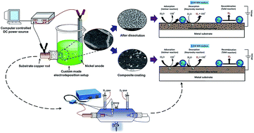
The codeposition of suspended TiO2 nanoparticles is effected from convective and diffusive mass transfer towards the electrode surface along with metal ions after attaining surface charge through ionic clouds on the particles.22,42 The as-deposited composite electrode having TiO2 nanoparticles within the alloy matrix, and on the surface as agglomerated particles are evidenced from the FESEM (Fig. 9). Thus incorporated TiO2 nanoparticles act as a catalytic centre, and are responsible for enhanced HER as explained by Gierlotka et al.43 The scheme showing the mechanism of incorporation of nanoparticles into the alloy matrix, responsible for the improved electrocatalytic activity of Ni–P–TiO2 coating is shown in Fig. 10.
 |
| Fig. 10 Schematic representation showing step by step illustration of the formation of composite electrodeposits from the nanoparticle loaded optimal alloy plating bath during electrodeposition. | |
Electrocatalytic study of composite coatings
To enhance the HER efficiency of Ni–P alloy coatings further by increasing the effective surface area and/or the intrinsic activity of the material, Ni–P–TiO2 composite coating was developed at an applied c.d. of 4.0 A dm−2. The Ni–P–TiO2 composite coating was tested for its electrocatalytic activity towards HER in same 1.0 M KOH using CV and CP techniques, as detailed earlier. The CV study of cathodic reaction for HER on Ni–P–TiO2 composite coatings are given in comparison with those of as-coated Ni–P alloy and anodically treated Ni–P alloy coatings in Fig. 11. The corresponding variation in HER parameters of each test electrodes of different types is tabulated in Table 5.
 |
| Fig. 11 CV curves demonstrating improvement in the electrocatalytic behavior for HER on the surface of Ni–P alloy coatings of different type. | |
The electrocatalytic behaviour of the composite coating developed at 4.0 A dm−2 was evaluated by CP method, alongside the quantitative measurement of H2 gas, in the same way as explained. The nature of chronopotentiograms for TiO2 incorporated composite coatings is shown in Fig. 12, in relation with those for as-coated, and anodically treated Ni–P alloy coatings, with the volumes of hydrogen gas liberated in the inset.
 |
| Fig. 12 Comparison of chronopotentiometry curves for HER on surface of Ni–P alloy coatings of different type, and volume of H2 evolved in 300 s on each test electrodes are shown in the inset. | |
The enhanced HER activity of the composite coating is attributed to the increased surface area and increase in the number of active sites through the incorporation of TiO2 nanoparticles. The mechanism of HER on different surfaces is schematically represented in Fig. 13. The increase in electrocatalytic activity of Ni–P alloy coating after dissolution treatment and TiO2 nanoparticle incorporation are mainly resulted from the change in electronic structure, surface area and the increase in active sites for hydrogen adsorption.29
 |
| Fig. 13 Schematic diagram showing the mechanism of HER on the surface of modified Ni–P alloy coatings in relation to it on as-plated Ni–P alloy coatings. Improved HER on modified electrode surface (electrochemically treated and TiO2 embedded Ni–P alloy coatings) may be attributed to the increased porosity and reactive sites respectively. | |
Conclusions
The Ni–P alloy coatings as a promising electrocatalyst for water splitting applications has been synthesized galvanostatically on copper using glycerol as an additive. Experimental investigation on electrocatalytic behavior for both HER and OER have been made. The poor electrocatalytic behavior of Ni–P alloy coatings towards HER has been improved further by electrochemical dissolution and TiO2 nanoparticle assisted electrodeposition methods, and following experimental observations were made as conclusions:
(1) Ni–P alloy coatings deposited at 4.0 A dm−2 and 2.0 A dm−2 were found to be efficient electrode materials for HER and OER reactions, respectively, demonstrated by CV and chronopotentiometry experiments. The CV study showed that the efficacy of Ni–P alloy coatings for HER is poor and less sensitive to the P content of alloy, compared to OER. The composition of deposit favouring cathodic reaction (HER) has an adverse effect on anodic reaction (OER) and vice versa.
(2) The electrocatalytic activities for HER and OER were found to have no linear relationship with P content of the deposit. Further, the best electrocatalytic activity is attributed to the synergistic effect of Ni and P, responsible for the formation of Ni–P alloy, having unique composition and phase structure.
(3) The improved electrocatalytic activity after anodic treatment is due to increase in the porosity of the coatings, leading to an increase in the surface area and thereby making active metal atoms to expose more to the electrolyte.
(4) The Ni–P–TiO2 composite coatings exhibited the highest electrocatalytic activity for HER (with highest cathodic peak c.d. of 0.38 A cm−2 and least onset potential of −1.19 V and highest volume of H2 liberated), compared to as-coated and anodically treated Ni–P alloy coatings, deposited from the same bath.
(5) Drastic improvement in the electrocatalytic character of HER on Ni–P–TiO2 composite coating is attributed to the formation of more number of electrocatalytically active centers, affected by the addition of TiO2 nanoparticles, added into the bath.
Acknowledgements
Liju Elias is thankful to NITK, Surathkal, India for supporting this research in the form of Institute Research Fellowship. Authors are thankful to the Department of Met. and Mat. Eng. NITK, Surathkal for extending XRD, SEM and EDS facilities for analyses.
References
- X. Zou and Y. Zhang, Chem. Soc. Rev., 2015, 44, 5148–5180 RSC.
- F. Safizadeh, E. Ghali and G. Houlachi, Int. J. Hydrogen Energy, 2015, 40, 256–274 CrossRef CAS.
- H. Ju, Z. Li and Y. Xu, Mater. Res. Bull., 2015, 64, 171–174 CrossRef CAS.
- B. V. Tilak, A. C. Ramamurthy and B. E. Conway, in Proceedings of the Indian Academy of Sciences-chemical sciences, Springer, 1986, vol. 97, pp. 359–393 Search PubMed.
- B. You, N. Jiang, M. Sheng, S. Gul, J. Yano and Y. Sun, Chem. Mater., 2015, 27, 7636–7642 CrossRef CAS.
- Z. D. Wei, A. Z. Yan, Y. C. Feng, L. Li, C. X. Sun, Z. G. Shao and P. K. Shen, Electrochem. Commun., 2007, 9, 2709–2715 CrossRef CAS.
- D. S. P. Cardoso, L. Amaral, D. M. F. Santos, B. Šljukić, C. A. C. Sequeira, D. Macciò and A. Saccone, Int. J. Hydrogen Energy, 2015, 40, 4295–4302 CrossRef CAS.
- D. Hou, W. Zhou, X. Liu, K. Zhou, J. Xie, G. Li and S. Chen, Electrochim. Acta, 2015, 166, 26–31 CrossRef CAS.
- M. A. Domínguez-Crespo, A. M. Torres-Huerta, B. Brachetti-Sibaja and A. Flores-Vela, Int. J. Hydrogen Energy, 2011, 36, 135–151 CrossRef.
- S. Trasatti, J. Electroanal. Chem. Interfacial Electrochem., 1972, 39, 163–184 CrossRef CAS.
- J. K. Nørskov, T. Bligaard, A. Logadottir, J. R. Kitchin, J. G. Chen, S. Pandelov and U. Stimming, J. Electrochem. Soc., 2005, 152, J23–J26 CrossRef.
- H. Li, W. Wang, Z. Gong, Y. Yu, H. Chen, J. Xia and others, J. Phys. Chem. Solids, 2015, 80, 22–25 CrossRef CAS.
- N. Kanani, Electroplating: basic principles, processes and practice, Elsevier, 2004 Search PubMed.
- E. Navarro-Flores, Z. Chong and S. Omanovic, J. Mol. Catal. A: Chem., 2005, 226, 179–197 CrossRef CAS.
- Y. Liu, X. Zhang, B. Quan, G. Ji and H. Zhang, Nanosci. Nanotechnol. Lett., 2015, 7, 840–845 CrossRef.
- P. Peeters, G. V. D. Hoorn, T. Daenen, A. Kurowski and G. Staikov, Electrochim. Acta, 2001, 47, 161–169 CrossRef CAS.
- J. Du, S. Xie, N. Li and L. Xu, Nanosci. Nanotechnol. Lett., 2000, 8, 382–386 CrossRef.
- R. K. Shervedani and A. Lasia, J. Electrochem. Soc., 1997, 144, 511–519 CrossRef.
- S. H. Ahn, S. J. Hwang, S. J. Yoo, I. Choi, H.-J. Kim, J. H. Jang, S. W. Nam, T.-H. Lim, T. Lim, S.-K. Kim and others, J. Mater. Chem., 2012, 22, 15153–15159 RSC.
- G. Lu and G. Zangari, Electrochim. Acta, 2002, 47, 2969–2979 CrossRef CAS.
- N. V. Parthasaradhy, Practical Electroplating Handbook, Prentice Hall, New Jersey, 1989 Search PubMed.
- C. T. J. Low, R. G. A. Wills and F. C. Walsh, Surf. Coat. Technol., 2006, 201, 371–383 CrossRef CAS.
- A. M. Pillai, A. Rajendra and A. K. Sharma, J. Coat. Technol. Res., 2012, 9, 785–797 CrossRef CAS.
- R. Narayan and M. N. Mungole, Surf. Technol., 1985, 24, 233–239 CrossRef CAS.
- T. Mahalingam, M. Raja, S. Thanikaikarasan, C. Sanjeeviraja, S. Velumani, H. Moon and Y. D. Kim, Mater. Charact., 2007, 58, 800–804 CrossRef CAS.
- T. Burchardt, Int. J. Hydrogen Energy, 2000, 25, 627–634 CrossRef CAS.
- L. Han, X. Li, J. Ma, Y. Yu and J. Lu, Nanosci. Nanotechnol. Lett., 2015, 7, 308–313 CrossRef.
- X. Zhu, X. Cui, Z. Che, X. Jin and M. Li, J. Nanosci. Nanotechnol., 2015, 15, 9717–9720 CrossRef CAS PubMed.
- M. Ledendecker, G. Clavel, M. Antonietti and M. Shalom, Adv. Funct. Mater., 2015, 25, 393–399 CrossRef CAS.
- S. A. Gawad, A. M. Baraka, M. S. Morsi and M. A. Eltoum, Int. J. Electrochem. Sci., 2013, 8, 1722–1734 Search PubMed.
- L. Elias, K. Scott and A. C. Hegde, J. Mater. Eng. Perform., 2015, 24, 4182–4191 CrossRef CAS.
- L. Elias and A. C. Hegde, J. Electrochem. Plat. Technol., 2016 DOI:10.12850/ISSN2196-0267.JEPT5393.
- T. Omi, S. Kokunai and H. Yamamoto, Trans. Jpn. Inst. Met., 1976, 17, 370–377 CrossRef CAS.
- F. Rosalbino, D. Maccio, E. Angelini, A. Saccone and S. Delfino, J. Alloys Compd., 2005, 403, 275–282 CrossRef CAS.
- Y. Ullal and A. C. Hegde, Int. J. Hydrogen Energy, 2014, 39, 10485–10492 CrossRef CAS.
- K. H. Kim, J. Y. Zheng, W. Shin and Y. S. Kang, RSC Adv., 2012, 2, 4759–4767 RSC.
- A. P. Brown, M. Krumpelt, R. O. Loutfy and N. P. Yao, Electrochim. Acta, 1982, 27, 557–560 CrossRef CAS.
- Y.-S. Lee, C.-C. Hu and T.-C. Wen, J. Electrochem. Soc., 1996, 143, 1218–1225 CrossRef CAS.
- C.-C. Hu, Y.-S. Lee and T.-C. Wen, Mater. Chem. Phys., 1997, 48, 246–254 CrossRef CAS.
- M. M. Jaksic, Solid State Ionics, 2000, 136, 733–746 CrossRef.
- A. Wieckowski, E. R. Savinova and C. G. Vayenas, Catalysis and electrocatalysis at nanoparticle surfaces, CRC Press, 2003 Search PubMed.
- R. Gómez, J. M. Feliu and A. Aldaz, Electrochim. Acta, 1997, 42, 1675–1683 CrossRef.
- D. Gierlotka, E. RO' Winski, A. Budniok and E. LA Giewka, J. Appl. Electrochem., 1997, 27, 1349–1354 CrossRef CAS.
Footnote |
† Electronic supplementary information (ESI) available. See DOI: 10.1039/c6ra09497j |
|
This journal is © The Royal Society of Chemistry 2016 |
Click here to see how this site uses Cookies. View our privacy policy here.