
Low viscosity-PLGA scaffolds by compressed CO2 foaming for growth factor delivery†‡
L. Diaz-Gomeza,
F. Yangb,
J. A. Jansenb,
A. Concheiroa,
C. Alvarez-Lorenzo*a and
C. A. García-González*a
aDepartamento de Farmacia y Tecnología Farmacéutica, Facultad de Farmacia, Universidade de Santiago de Compostela, E-15782 Santiago de Compostela, Spain. E-mail: carmen.alvarez.lorenzo@usc.es; carlos.garcia@usc.es; Fax: +34 981 547148; Tel: +34 881 815239 Tel: +34 881 815252
bDepartment of Biomaterials, Radboud University Medical Center, 6500 HB Nijmegen, The Netherlands
First published on 18th July 2016
Abstract
Foaming technology using supercritical and compressed fluids has emerged as a promising solution in regenerative medicine for manufacturing porous polymeric scaffolds. Polymers of low inherent viscosity are particularly attractive as scaffold components due to their adequate degradation rate and clearance profiles. However, these polymers lead to scaffolds with limited physical integrity if conventional compressed CO2 foaming is used for their processing. To this end, a modified compressed CO2 foaming method was developed for the processing of mixtures of low inherent viscosity poly(lactic-co-glycolic acid) (PLGA, 0.2 dL g−1) and poly(ε-caprolactone) (PCL). The compatibility of the method with the incorporation of growth factors and the role of other admixtures (pregelifed starch) in the scaffold were assessed. Scaffolds were obtained in the form of monoliths and characterized in terms of morphology, physicochemical, and viscoelastic properties; biological tests were carried out to evaluate their ability to promote tissue formation. Scaffolds showed good cell attachment and growth. Results showed that the scaffold composition determined the mechanical and biological performance of the construct and influenced the release profile of the incorporated growth factors.
Introduction
Synthetic scaffolds for grafting applications should have a biocompatible matrix that is able to mimic the physiological functions of the extracellular matrix and thereby attract cells and enable the regeneration of the lacking tissue. Besides, the biodegradation rate of the scaffold should be compatible with the growth rate of the tissue. In addition, the porous structure of the scaffold should serve as a template to promote the attachment, proliferation and reorganization of cells as well as to allow the neovascularisation and access of nutrients and gases to the cells.1,2Polyesters are approved components of scaffolds.3 For example, poly(lactic-co-glycolic acid) (PLGA) is particularly suitable for application in implantable devices since its physical, mechanical and degradation properties can be tuned by changing the lactic![[thin space (1/6-em)]](https://www.rsc.org/images/entities/char_2009.gif) :glycolic (L/G) monomer ratio, the molecular weight or the crystallinity.4,5 PLGA with an L/G ratio of 50:50 and a low molecular weight (inherent viscosity lower than 0.5 dL g−1) degrades at a rate (degradation time of 8–10 weeks) that is compatible with the tissue ingrowth rate.4,6 However, low inherent viscosity PLGA usually leads to poor mechanical properties for the scaffold and to an inadequate control of the release of bioactive compounds.7,8
:glycolic (L/G) monomer ratio, the molecular weight or the crystallinity.4,5 PLGA with an L/G ratio of 50:50 and a low molecular weight (inherent viscosity lower than 0.5 dL g−1) degrades at a rate (degradation time of 8–10 weeks) that is compatible with the tissue ingrowth rate.4,6 However, low inherent viscosity PLGA usually leads to poor mechanical properties for the scaffold and to an inadequate control of the release of bioactive compounds.7,8
Among the scaffold preparation techniques, compressed CO2 foaming technology is attractive as a reproducible and green processing approach since no organic solvents are used and the process operates under mild conditions.9,10 This technique has been proved to be compatible with temperature sensitive compounds such as growth factors.11 Scaffolds containing growth factors have been prepared by this process, but until now, the use of the compressed CO2 foaming method has been restricted to matrices made from high inherent viscosity polymers with degradation times greater than two months.8,11,12 Specifically, in the case of PLGA, CO2 sorption firstly takes place in the PLGA matrix after which pores are generated during CO2 removal through a nucleation/growth mechanism leading to a solvent-free porous matrix. As mentioned above, this foaming technique has been restricted so far to PLGA with an inherent viscosity higher than 0.5 dL g−1, because, below this threshold value, there is significant expansion of the foam that leads to the breakup of the material.8 Sintering of PLGA microspheres using compressed CO2 at low pressures (15–30 bar) and ambient temperature (25 °C) is an alternative method for processing scaffolds from low inherent viscosity PLGA but having low porosities (<45%). If bioactive agents such as growth factors need to be incorporated in the scaffold, an encapsulation step in the microspheres prior to sintering would be required.13 Moreover, the sintered scaffolds show pores with convex curvatures, which may have a negative impact on the tissue growth process.14
The combination of low inherent viscosity PLGA with other polymers of higher inherent viscosities is considered to be an interesting approach to tune the physicochemical and mechanical properties of the scaffold and to meet the required specifications of the host tissue.7 Poly-ε-caprolactone (PCL) may reinforce the mechanical properties of the scaffold for bone tissue repair.15 Moreover, the incorporation of polysaccharides in scaffold formulations may be advantageous for regulating the release of bioactive compounds.11,16,17 For instance, starch, which is a polysaccharide mainly composed of amylose and amylopectin, is especially attractive for the controlled release of active compounds due to its capacity to form inclusion complexes.18,19 Starch also favours the adhesion, proliferation and differentiation of cells.20 However, native starch is usually available in the form of partially crystalline granules that are difficult to blend with synthetic polymers.21,22 Chemical modification or gelation of starch using plasticizers may enhance the interaction of the resulting starch derivative with synthetic polymers.11,23
In this work, an upgraded compressed fluid foaming method is proposed to overcome the current limitations encountered in the processing of porous synthetic scaffolds containing PLGA of inherent viscosity lower than 0.5 dL g−1. PCL:PLGA (50:50, weight ratio) scaffolds in the form of monoliths were obtained using compressed CO2 (60 bar, 27 °C) foaming followed by a customized depressurization process. The suitability of this processing approach for thermally sensitive bioactive agents was assessed by the incorporation of lyophilized platelet-rich plasma (lPRP) extracted from an autologous source and containing some of the key factors involved in natural tissue regeneration.24 The effect of the incorporation of pre-gelified starch in the porous PCL/PLGA composite for the controlled release of growth factors was also investigated.
Results and discussion
Development of the processing method for scaffolds
PLGA and PCL were chosen as the main components of the composite (Table 1). The combination of PLGA of low inherent viscosity and PCL serves to tune the degradation profile and mechanical properties to be more compatible with the tissue regeneration rate compared to other higher molecular weight polymers. lPRP is safe, easy to obtain and a cost-effective alternative source of growth factors.25,26 Therefore, lPRP was used in this study as the bioactive compound. Starch was incorporated in some of the scaffold formulations as a non-cytotoxic and versatile ingredient to efficiently control the release of the bioactive compound.27,28 Starch was pre-gelified using two different drying conditions: oven-drying (StO) and freeze-drying (StL), because, it is well known that gelation conditions can influence the physicochemical properties of the resulting starch.29:PLGA (50:50, weight ratio) with different proportions of growth factors (lPRP) and pre-gelified starch (oven-dried = StO, or freeze-dried = StL) using compressed CO2 foaming
| Sample | PCL, wt% | PLGA, wt% | lPRP wt% | StO wt% | StL wt% |
|---|---|---|---|---|---|
| PCGL | 50 | 50 | — | — | — |
| PCGL-lPRP | 47.5 | 47.5 | 5 | — | — |
| PCGL-StO | 45.0 | 45.0 | — | 10 | — |
| PCGL-StO-lPRP | 42.5 | 42.5 | 5 | 10 | — |
| PCGL-StL | 45.0 | 45.0 | — | — | 10 |
| PCGL-StL-lPRP | 42.5 | 42.5 | 5 | — | 10 |
When a conventional compressed CO2 foaming method is used, matrices prepared with low inherent viscosity polymers (typically lower than 0.5 dL g−1) are not sufficiently resistant to pore volume expansion after nucleation, which leads to the formation of large pores (higher than 1 mm) upon CO2 depressurization (Fig. 1a, left and b) or even to the loss of the physical integrity of the material.8 Hence, the weak porous materials so obtained, cannot be used in biomedical applications.
 | ||
| Fig. 1 Images of (a) PCGL compact (centre) foamed without (left) and with (right) liquid CO2 addition during the depressurization step and (b) cross section of a PCGL scaffold processed without liquid CO2 addition showing very large pores due to an uncontrolled pore expansion. | ||
In view of the technical limitations in the use of the compressed CO2 foaming process for polymers of low inherent viscosity, it is necessary to advance the state-of-the-art by developing a suitable procedure for these polymers. The current method focuses on a one-pot process that enables to control the pore volume expansion of the polymeric matrix but has little impact on the overall processing time when compared to conventional compressed CO2 foaming processes. To validate this model, polymer mixtures containing PLGA with a markedly low inherent viscosity value (0.2 dL g−1) was used as a challenging model system in the processing. The technical solution developed in this work to overcome the aforementioned limitations was the addition of a cold liquid (CO2 at 1 °C and 60 bar), while the foaming system was still pressurized. The addition of liquid CO2 reduced the operating temperature and subsequently increased the viscosity of the polymeric matrix as well as the resistance to pore volume expansion during the depressurization process. Compressed liquid CO2 at 1 °C and 60 bar was therefore added three times in the foaming vessel during depressurization when the operating pressure reached 30 bar. This procedure gradually reduced the operating temperature in the vessel. This processing approach can be considered as non-contaminating in the sense that CO2 is an ingredient already present in the process and leaves no residues in the scaffold, since it is gaseous under ambient conditions. As a result, porous scaffolds with low density and with mechanical integrity (Table 2) in the form of monoliths were obtained (Fig. 1a, right) and used in characterization experiments.
| Scaffold | ρapp, g cm−3 | ρskel, g cm−3 | ε, % | Foam expansion, % | ABET, m2 g−1 | Vp,BJH, cm3 g−1 | dp,BJH, nm | AMIP, m2 g−1 | Vp,MIP, cm3 g−1 | dp,MIP, μm | εMIP, % |
|---|---|---|---|---|---|---|---|---|---|---|---|
| PCGL | 0.31(0.05) | 0.893(0.004) | 71.2(1.7) | 318(25) | 3.0(1.0) | 0.0022(0.0004) | 4.6(1.2) | 7.8 | 1.3 | 0.6 | 59.7 |
| PCGL-lPRP | 0.35(0.04) | 0.914(0.006) | 61.9(4.6) | 198(46) | 1.7(0.2) | 0.0014(0.0007) | 4.2(1.7) | 8.3 | 1.0 | 0.5 | 53.3 |
| PCGL-StO | 0.35(0.04) | 0.916(0.007) | 61.7(4.0) | 211(46) | 2.9(0.6) | 0.0014(0.0007) | 4.1(0.3) | 7.5 | 0.8 | 0.4 | 48.4 |
| PCGL-StO-lPRP | 0.36(0.09) | 0.937(0.007) | 61.2(8.6) | 168(16) | 1.7(0.1) | 0.0031(0.0002) | 4.7(0.2) | 11.5 | 1.5 | 0.5 | 63.1 |
| PCGL-StL | 0.36(0.02) | 0.913(0.005) | 61.0(2.1) | 203(19) | 2.3(0.7) | 0.0015(0.0009) | 3.7(0.5) | 10.2 | 1.5 | 0.6 | 63.2 |
| PCGL-StL-lPRP | 0.37(0.01) | 0.934(0.007) | 60.3(0.9) | 165(7) | 1.7(0.2) | 0.0014(0.0001) | 3.8(0.2) | 11.8 | 1.3 | 0.4 | 59.9 |
Scaffolds characterization
Biodegradable scaffolds with an open porosity able to support cell growth were prepared in this work. Pore morphology was tuned during the foaming process to obtain a specific porosity. Most pores had sizes above 0.1 μm (threshold between BET and MIP detection regions) as indicated by the large contribution of the pore volume measured by mercury-intrusion porosimetry (Vp,MIP) to the textural properties when compared to results from nitrogen adsorption/desorption isotherms (Vp,BJH) (Table 2). After the foaming process, the volume of the PCGL scaffolds increased up to 4 times with respect to the original tablet volume (i.e. foam expansion ranging from 165 to 318%). Incorporation of lPRP resulted in a significant decrease in the volume expansion of the PCGL scaffolds after the near-critical CO2 foaming, leading to an increase of ca. 10–15% in apparent density and a decrease of ca. 15% in porosity compared to their counterparts without lPRP. Accordingly, the densification caused by lPRP also led to a reduction in the overall pore volume (sum of Vp,BJH and Vp,MIP). Nevertheless, the specific surface area (sum of ABET and AMIP) was almost constant since the decrease in porosity due to lPRP incorporation was compensated by the decrease in the mean pore size (dp,MIP). Incorporation of pre-gelified starch (StO, StL) in the PCGL scaffolds also reduced the swelling of the material upon foaming resulting in increased apparent density and reduced porosity. However, this has a low impact on the overall pore volume and specific surface area values.The fact that a certain fraction of pores (ca. 15%) in the scaffolds were closed was revealed by the discrepancy between the open porosity εMIP results and the overall porosity ε for some of the samples (Table 2). This is in accordance with other results reported in the literature on compressed CO2 foaming of biomaterials.8,30,31 The scaffolds showed an interconnected porous structure with pores in the 50–200 μm range as shown in the SEM images (Fig. 2). Foaming of polymers with low molecular weight generally results in structures that are more heterogeneous than those observed for higher molecular weight polymers.32 Starch (either StO or StL) did not significantly modify the topography and the pore distribution of the scaffolds. This indicates a homogeneous mixing of starch with PCL and PLGA. The presence of lPRP in the scaffolds also did not alter the topography, which implied that the CO2 foaming did not lead to protein segregation. This conclusion was confirmed by analysing the distribution of the FITC-marked lysozyme, which was used as a protein model, in the scaffolds. Results (Fig. S1 in ESI‡) demonstrated that lys-FITC was randomly dispersed throughout the scaffold matrix. Therefore, the present method involving the pressing of the raw materials to form tablets followed by near-critical CO2 foaming appears to be particularly suitable to obtain porous scaffolds with a homogeneous distribution of growth factors.
 | ||
| Fig. 2 SEM micrographs of PCGL (A), PCGL-lPRP (B), PCGL-StO (C), PCGL-StO-lPRP (D), PCGL-StL (E) and PCGL-StL-lPRP (F) scaffolds processed with compressed CO2. | ||
The effect of the compressed CO2 foaming process on the thermal properties of the scaffolds was evaluated using differential scanning calorimetry (DSC, Table 3). The PCL raw material showed a melting point of 61.4 °C, a melting enthalpy of 94.7 J g−1 and a crystallinity of 66.7%, whereas PLGA had a glass transition temperature (Tg) of 36.2 °C. After the treatment with compressed CO2, the PCGL scaffold showed two melting peaks: the first at 48.0 °C (Tm,1) and a second at 61.8 °C (Tm,2). No glass transition endotherm could be ascertained in the DSC scans. The depression in the melting temperature of PCL in the presence of CO2 has been reported to follow a linear trend with pressure with a slope of ca. −0.3 °C bar−1 in the 10–50 bar pressure range.33
| Scaffold | 1st heating | 1st cooling | 2nd heating | ||||
|---|---|---|---|---|---|---|---|
| Tm,1 (°C) | Tm,2 (°C) | ΔHm (J gPCL−1)a | Tcryst (°C) | ΔHcryst (J gPCL−1) | Tm,2 (°C) | ΔHm (J gPCL−1) | |
| a ΔHm was obtained from the integration of the Tm,1 and Tm,2 peaks. | |||||||
| PCGL | 48.0 | 61.8 | 102.3 | 26.8 | 71.2 | 55.9 | 75.2 |
| PCGL-lPRP | 50.8 | 60.8 | 100.1 | 27.5 | 67.7 | 55.0 | 68.2 |
| PCGL-StO | 45.8 | 60.1 | 80.8 | 27.7 | 55.8 | 55.2 | 52.8 |
| PCGL-StO-lPRP | 48.6 | 60.6 | 95.2 | 27.7 | 61.0 | 56.1 | 62.4 |
| PCGL-StL | 47.1 | 60.6 | 89.5 | 27.3 | 61.5 | 55.5 | 60.3 |
| PCGL-StL-lPRP | 48.0 | 60.1 | 89.8 | 28.4 | 56.4 | 55.0 | 58.9 |
On the other hand, the Tg value of PLGA decreased initially upon contact with compressed CO2 due to the plasticizing effect arising from the interaction between CO2 and carbonyl groups present in PLGA34 after which the Tg increased above the initial value for PLGA due to the rapid solidification of the polymer following depressurization.35 Therefore, a partial melting of PCL and plasticization of PLGA occurred under the foaming conditions used in this work (60 bar, 27 °C). The fraction of PCL that melted during soaking in compressed CO2 could form small crystallites during depressurization due to the rapid decrease in the plasticizing effect of CO236 and this could be responsible for the first melting peak Tm,1 in the DSC scans. Indeed, the absence of this peak during the second heating cycle supports this assignment. The Tg of PLGA overlapped with the first melting point of PCL and could not be estimated during the first heating cycle, but could be evaluated for the second heating cycle since the Tm,1 peak was absent. This overlapping of peaks would explain the increase in the melting enthalpy of the PCGL sample (expressed with respect to the weight content in PCL of the sample) observed after the first heating cycle compared to raw PCL. PCL was completely melted during the first heating cycle of the DSC analysis which favoured the PCL-PLGA interaction; PCL recrystallized during the cooling cycle. The decrease in the melting enthalpy of PCGL after the second heating cycle was attributed to the increased PCL-PLGA interaction leading to a reduced crystallinity of the sample.
The thermal behaviour of PCGL scaffolds with starch admixture depended on the pre-treatment used for the polysaccharide. Both the melting points (Tm,1 and Tm,2) as well as the melting enthalpy of the scaffolds (ΔHm) decreased with the incorporation of starch, this tendency being more significant for the oven-dried starch (StO). This behaviour was attributed to the reduced crystallinity of PCL when pre-gelified starch was incorporated in the scaffold formulation that led to an improved PCL-starch interaction.11,37 The differences in the thermal behaviour observed for scaffolds with freeze-dried (StL) and oven-dried (StO) starches were related to the differences in the thermo-physical modifications, water content and the amylose–amylopectin spatial re-arrangement in these two starches, which are specific to the corresponding drying processes.29,38
The presence of low amounts of lPRP (5 wt%) in the scaffold slightly decreased the ΔHm and the Tm,2 value of the resulting scaffolds indicating some interaction between PCL and lPRP. In other words, the combination of lPRP with pre-gelified starch led to an increase in the melting enthalpy and two melting temperatures, notably in the case of the PCGL-StO-lPRP scaffold. The hydrophilic starch has a higher affinity for the lPRP component than for the hydrophobic polymers of the scaffolds (PCL and PLGA). As a result, the interaction of PCL with the other ingredients of the scaffold was reduced and the crystallinity was higher.
Ideally, the in vivo degradation rate of the scaffolds should be similar to the tissue formation rate.39 All the scaffolds processed by compressed CO2 foaming showed similar biphasic degradation profiles after incubation for two months in PBS at 37 °C (Fig. 3). It is known that PLGA degradation preferentially occurs by the hydrolysis of the ester bonds into oligomeric and monomeric products of lactic and glycolic acids, which are non-toxic and can be transformed into carbon dioxide and water (tricarboxylic acid cycle) or excreted in urine.5 The surface erosion of PCL is attributed to the hydrolytic chain scission of the ester linkages, resulting in the release of oligomers and monomers with lower molecular weight, which rapidly diffuse into the surrounding medium.40 Starch degradation to maltose, glucose and dextrin mainly follows an enzymatic mechanism driven by amylases, especially α-amylase, which are present in the blood (serum).41
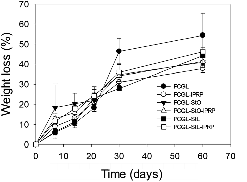 | ||
| Fig. 3 Degradation profiles of the scaffolds after incubation during 60 days in PBS at 37 °C. Error bars denote standard deviation (n = 3). | ||
Once immersed in aqueous medium, PCGL, PCGL-StL and PCGL-StO scaffolds without lPRP increased their weight by 50.9 (3.9), 55.0 (3.8) and 65.3 (0.7)% after six hours. The same scaffolds containing lPRP sorbed significantly larger amounts of water, increasing the weight 108.2 (0.9), 126.5 (1.5), and 117.3 (1.9)%, respectively. The weight loss observed in the scaffolds during the first 30 days (Fig. 3) can be attributed to low molecular weight PLGA that degrades faster than PCL.42 At the end of four weeks, the degradation rate was attenuated. At day 60, all the scaffolds were significantly degraded and showed weight losses in the 37–55% range. Individually, the PCGL scaffolds were degraded extensively losing up to 55% of their weight after 60 days in PBS. Scaffolds containing starch (StO and StL) showed lower degradation rates with weight losses of ca. 40%. After two months, the topography of the scaffolds was significantly altered as observed in SEM images (Fig. S2‡). For the scaffolds containing lPRP, the presence of starch had no effect on the degradation of the matrix.
Regarding mechanical properties, freshly prepared scaffold slabs (7 mm thickness) showed at 37 °C storage (G′) and loss moduli (G′′) above 108 and 107 Pa, respectively (Fig. S3‡). Bone implants need to be compatible with the mechanical properties of the surrounding tissue. In the case of human cortical bone, the storage and loss moduli are in the GPa scale.43,44 The viscoelastic behaviour and damping capability values of the PCGL scaffolds are in good agreement with previously reported data for PCL-starch-lPRP scaffolds.11 Scaffolds containing lPRP were less fragile and showed constant values of G′ and G′′ regardless of the applied angular frequency. Conversely, the PCGL-StL scaffolds lost the physical consistency when exposed at 37 °C to angular frequencies above 10 rad s−1. The incorporation of growth factors also increased the thermal stability of the scaffolds, as demonstrated by the evolution of the tanδ values (=G′′/G′) (Fig. S4‡). Scaffolds without lPRP showed a drop in G′ modulus (and thus an increase in tanδ) at temperatures above 39 °C, due to the glass transition of PLGA. In the case of lPRP-loaded scaffolds, tanδ remained practically constant up to 41 °C.
Protein release
Protein release from the scaffolds was significantly influenced by the scaffold formulation (Fig. 4). In the first six hours, a rapid release of the growth factor was observed in all the cases presumably due to the presence of lPRP on the surface and the pores walls of the scaffolds, which favoured water uptake. After 24 hours, the release rate slowed down since entrapped growth factors can leave the scaffold only after the hydrolysis of the polymer.5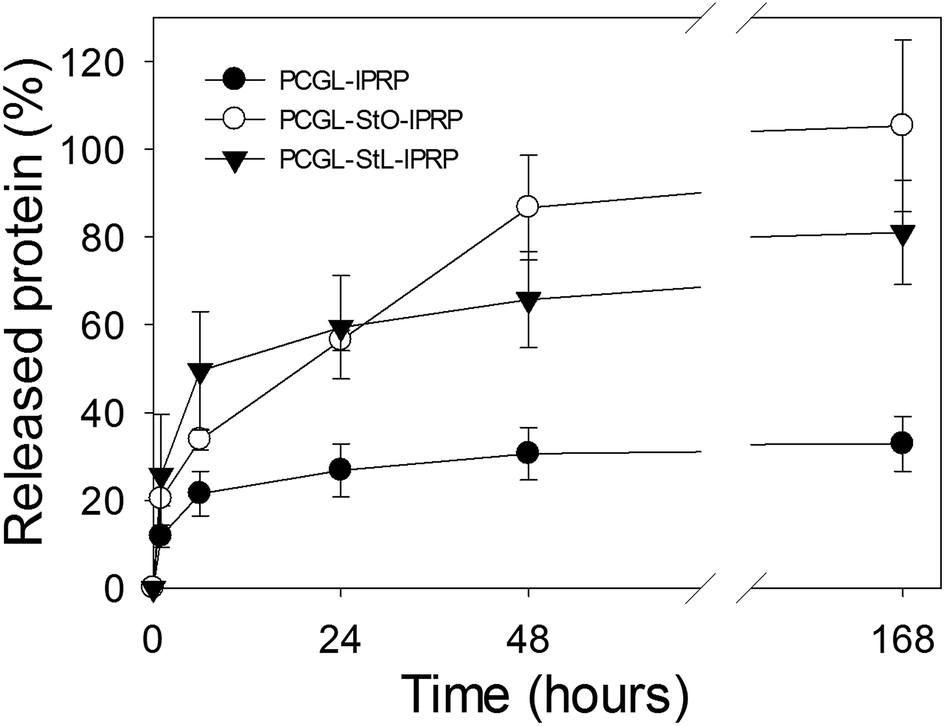 | ||
| Fig. 4 Cumulative release of lPRP from PCGL-lPRP, PCGL-StO-lPRP and PCGL-StL-lPRP scaffolds after one week in PBS at 37 °C. Error bars denote standard deviation (n = 3). | ||
Starch played a major role in lPRP release since it reduced the interaction between lPRP and PCGL as already ascertained from thermal studies (DSC). Accordingly, after one week, the PCGL-StL-lPRP scaffold released over 70% of the payload, and PCGL-StO-lPRP released almost 100% of its payload. In scaffolds containing pre-gelified starch, the release of lPRP is likely to be driven by two mechanisms: (i) the rapid dissolution (burst) of growth factors present on the surface of the scaffold and on the outer pores, and (ii) their sustained diffusion through the hydrogel layer formed by starch.45 Scaffolds containing starch (StO and StL) were more hydrophilic than scaffolds with only PCGL resulting in an increase in the volume of the bulk structure for the former, due to a greater penetration of water into the matrix. This also results in the release of the growth factors from the interior of the scaffolds at a higher rate than from PCGL-only scaffolds. The method used for the drying of starch also influences the water uptake and the release of the active agents from the scaffolds. Starch processed by freeze-drying has lower ability to form gel layer with respect to oven-dried starch.37 Thus, the release was initially faster from PCGL-StL-lPRP scaffold (Fig. 4).
Cell attachment and proliferation
The proliferation of MSC seeded on the polymeric scaffolds was evaluated by DNA quantification using QuantiFluor dsDNA assay (Promega; Madison, WI, USA) (Fig. 5). Enzymatic assays, such as MTT or Alamar Blue, were not suitable because the coloured products stained the scaffold altering the results. | ||
| Fig. 5 DNA content of PCGL scaffolds after 1, 3 and 7 days in culture. Error bars represent standard deviation (n = 3). Intraday-results were statistically compared (p < 0.01 at 1 and 3 days and p < 0.05 at day 7). Equal letter means statistically homogeneous groups. | ||
After 1, 3 and 7 days, more cells were observed on the scaffolds containing lPRP compared to the counterparts without lPRP. It has been previously reported that the incorporation of lPRP in porous scaffolds may enhance cell attachment and proliferation due to the presence of fibronectin and vitronectin.46–48 Although lPRP from different sources may have a different content of growth factor, it has been shown that lPRP increases the adhesion and proliferation of MSCs and other cell lines and promotes the synthesis of extracellular matrix.49–51
After 1 day, there were notable differences in the cell content between the PCGL-StL and the PCGL-only scaffolds. The increased cell attachment in the formulations with pre-treated starch can be attributed to an increase in the hydrophilicity of the scaffolds.52 Nevertheless, the initial enhancement effect of StL on cell proliferation was attenuated and a similar number of cells were found on all the three scaffolds without lPRP after 3 and 7 days.
Scaffolds cytotoxicity
The cytotoxicity of the scaffolds was tested using Live–Dead analysis (Fig. 6). Cell viability was demonstrated by the presence of a large number of green-stained cells on the scaffolds. The few red-stained cells that were observed could be associated to the acidic environment resulting from PLGA degradation. Further investigations are necessary to evaluate the role of the acidic by-products of PLGA degradation on cell growth on a long term. Nevertheless, it is expected that the greater exchange of fluids in the implant site in vivo as compared to the in vitro conditions, would lead to a decrease in the concentration of these acidic by-products of PLGA degradation in the local environment. This phenomenon would also suppress the autocatalytic process resulting in a lower degradation rate of the scaffolds.53 | ||
| Fig. 6 Live–Dead staining of MSC seeded on the scaffolds cultured for 3 days ((A) PCGL, (B) PCGL-lPRP, (C) PCGL-StO, (D) PCGL-StO-lPRP, (E) PCGL-StL (F) PCGL-StL-lPRP). Live cells are in green (calcein) and dead cells in red (ethidium homodimer). Scale bars: 200 μm. | ||
Experimental
Materials
Poly(ε-caprolactone) (PCL, Mw 50 kDa) was purchased from Polysciences (Warrington, PA, USA), PLGA (PDLG 5002A, L/G ratio 50:50, Mw 15 kDa, inherent viscosity 0.16–0.24 dL g−1) from Purac (Gorinchem, The Netherlands) and starch from Roquette (Amylo N-460, 52.6% amylose content; Lestrem, France). CO2 was supplied by Praxair, Inc. (Danbury, CT, USA). αMEM medium, fetal bovine serum (FBS) and penicillin/streptomycin were obtained from Gibco (Life Technologies, Bleiswijk, The Netherlands). Fluorescein isothiocyanate (FITC) and lysozyme from chicken egg were from Sigma-Aldrich (St Louis, MO, USA). Human adipose derived mesenchymal stem cells (MSCs; ATCC PCS-500-011) were obtained from the American Type Culture Collection (LGC Standards SLU; Barcelona, Spain). Water was purified using reverse osmosis (resistivity > 18 MΩ cm; MilliQ, Millipore®, Spain).
lPRP preparation
Human buffy coat was obtained from healthy donors at the Centro de Transfusión de Galicia (Santiago de Compostela, Spain) and centrifuged for 15 min at 400g. The study was approved by the Committee of Ethics Research of the Xunta de Galicia. All donors provided informed consent before blood extraction, and all procedures were in accordance with the Helsinki Declaration. The upper fraction containing a high platelet concentration (PRP) was collected. Platelets were activated by four freeze–thaw cycles (−80 °C for 24 h, room temperature for 1 h) to allow the release of growth factors from alpha and dense granules. PRP was centrifuged at 14000g for 10 min at 4 °C to separate the growth factors from platelet debris. The concentration of VEGF was determined by means of an ELISA assay (RayBiotech, USA). The supernatant was frozen at −80 °C and lyophilized, and the obtained dry lPRP powder was stored at −80 °C until use.
Starch preparation
An aqueous dispersion of starch (10 wt%) was heated at 90 °C for 20 min until gelation and placed at 4 °C for 48 h for retrogradation. Oven heating (80 °C, one day) or freeze-drying (LyoQuest Plus −85 °C/ECO, Telstar; Terrassa, Spain) were used for drying the starch gel leading to starch powders denoted as StO and StL, respectively. The starch powder was ground in a ball mill mixer Mix MM 400 (Retsch Inc., Newton, PA, USA) to obtain a white powder with particle sizes lower than 20 μm.Scaffolds preparation
Scaffolds were prepared by using high pressure equipment (Thar Technologies, Pittsburgh, PA, USA) with compressed CO2 as the foaming agent. Briefly, powdered mixtures (Table 1) were homogenized in a mortar and mixed in a Turbula mixer (WAB AG Maschinenfabrik, T2C, Switzerland) for 10 min. The mixtures were preconditioned to prepare tablets in the form of rectangular parallelepipeds (14 × 10 × 2.65 mm, 400 mg) using a Korsch EKOW 66 eccentric tablet press machine (Korsch AG, Frankfurt am Main, Germany). The tablets were placed in a 100 mL stainless steel autoclave and processed under near-critical conditions (60 bar, 27 °C) for 30 min while rotating at 700 rpm. The autoclave was depressurized at the rate of 5 bar min−1 with three intermediate additions of 10–15 g of liquid CO2 (60 bar, 1 °C). Finally, the outer non-porous layer of the scaffolds was removed and the scaffolds were cut with a scalpel into cubes (5 mm side) for further use.Scaffolds characterization
Porosity of the scaffolds including the pore size distribution, total pore volume (Vp,MIP), specific surface area (AMIP), mean pore diameter (dp,MIP) and open porosity (εMIP) were determined by mercury-intrusion porosimetry using a Micromeritics 9305 pore sizer (Micromeritics Instrument Corp; Norcross, GA, USA). Working pressures were from 0.07 to 1723 bar. Nitrogen adsorption–desorption tests were also performed to characterize the porosity of the scaffolds. Specific surface areas (ABET) were determined using the Brunauer–Emmett–Teller method (BET). Pore volume (Vp,BJH) and mean pore diameter (dp,BJH) were estimated using the Barrett–Joyner–Halenda method (BJH). Scaffolds were degassed at 25 °C and 10−3 mbar overnight before porosity measurement. Samples were exposed to N2 gas at −196 °C and 0.01–0.98 relative pressure using an ASAP 2000 physisorption analyzer (Micromeritics Instrument Corporation; Norcross, GA, USA).The skeletal density (ρskel) of the scaffolds was determined from five replicates by gas displacement measurements using a helium-pycnometer (Quantachrome; Boynton Beach, FL, USA) at the operating conditions of 25 °C and 1.03 bar. The apparent density (ρapp) of the scaffolds was determined by measuring the dimensions and weight of the samples after processing. Overall porosity (ε) was calculated according to eqn (1)
 | (1) |
Foam expansion of the scaffolds after compressed CO2 processing was obtained using eqn (2)
 | (2) |
The scaffolds were immersed in liquid nitrogen for freezing, fractured into cubes with a scalpel and observed using a high-resolution field emission SEM (JSM-6460LV, JEOL, Japan).
The location of proteins in the scaffolds was carried out after replacing lPRP by a fluorescent labelled lysozyme (lys-FITC). Briefly, 100 mg of the lysozyme and 0.5 mg of FITC were dissolved in 5 mL of 0.25 M carbonate–bicarbonate buffer (pH 9) and stirred for 2 h at 4 °C. Next, the solution was dialysed (dialysis membrane, MWCO 2500 Da) against deionised water for 48 h to remove un-reacted FITC and freeze-dried. Scaffolds with lys-FITC instead of lPRP were processed using a similar procedure. The scaffolds were cut at the sides with a scalpel and the surface was observed by laser confocal fluorescence microscopy (LCS, Leica Microsystems, Germany) with excitation and emission wavelengths of 495 and 519 nm, respectively.
DSC scans of polymers and scaffolds were recorded in a DSC Q-100 apparatus (TA Instruments, New Castle, DE, USA) fitted with a refrigerated cooling system. The samples were heated from room temperature to 200 °C, cooled to 0 °C and heated again up to 200 °C at 10 °C min−1 under N2 atmosphere.
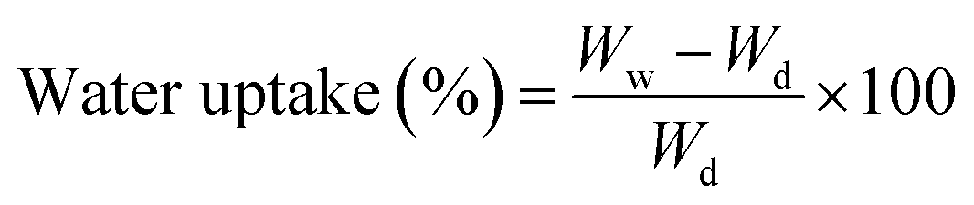
Water uptake of scaffold pieces (30–40 mg) was monitored by recording the weight at various times after immersion in water. The uptake was referred to the dry weight of the scaffolds, as follows
 | (3) |
For the degradation tests, scaffold pieces (25 mg) were immersed in 1 mL of PBS (pH 7.4, 37 °C, 30 rpm) and the degradation rate was determined by monitoring the weight loss up to 12 weeks; the medium was changed once a week. Before sampling, the scaffolds were rinsed with water, frozen, freeze-dried and weighed. Several scaffold sample pieces were used for each measurement. The weight loss was calculated as follows
 | (4) |
The storage (G′) and loss (G′′) moduli of the scaffold pieces (16 × 13 × 7 mm) were recorded using a Rheolyst AR 1000 N rheometer (TA Instruments, New Castle, DE, USA) equipped with a data analyser (AR2500), an environmental test chamber and a solid torsion kit. The samples were fixed between two clamps with a gap of 8 mm and analysed in duplicate at 37 °C, applying an angular frequency sweep between 5 and 100 rad s−1 at 0.5% strain. The variation of G′ and G′′ as a function of temperature was evaluated in the 25–45 °C range at 0.5% strain and 5 rad s−1 angular frequency.
Protein release
Cubic scaffold pieces (5 mm side; in triplicate) were placed in Eppendorf LoBind tubes (low protein retention tubes, Eppendorf, Germany) containing PBS (1 mL) and incubated at 37 °C under stirring (30 rpm). At pre-established times, 0.5 mL of the medium was collected and the tubes were refilled with 0.5 mL of fresh PBS. Aliquots were kept frozen at −80 °C until analysis. BCA assay (Pierce ThermoSci, Rockford, IL, USA) was used to quantify the total protein release from the scaffolds. The calibration curve was obtained from BSA solutions with concentrations up to 2 mg mL−1.Cell seeding
MSCs were seeded in a 175 cm3 flask and cultured using MesenPro RS (96%), MesenPro growth supplement (2%), glutamine (1%), and antibiotics (penicillin–streptomycin; 10000 U mL−1 and 10000 μg mL−1, respectively) (1%) at 37 °C (95% relative humidity and 5% CO2). Cells were cultured in an incubator and the medium was changed every third day. For scaffold seeding, the cells were detached from the flask by trypsinization (trypsin–EDTA solution 0.25%, Sigma-Aldrich, St Louis, MO, USA). CO2 used upon foaming also acted as sterilizing agent for the scaffolds.11 Moreover, cell culture and seeding were carried out in a proliferation culture medium containing broad-spectrum antibiotics (penicillin–streptomycin, 1%) as a preventive complementary measure to ensure microbial inactivation. Scaffold cubes (5 mm side) were soaked in the culture medium, after which they were placed in syringes that were filled with a cell suspension (2 × 10⁵ cells per mL, 1 mL, 3 scaffolds per mL) with the luer taper (upwards) fitted with a 0.22 μm filter and incubated at 37 °C under slow rotation for 3 h.
Cell attachment and proliferation
MSCs-seeded scaffolds were placed in non-adherent 24-well plates and cultured as in the previous paragraph. After 1, 3 and 7 days, DNA was extracted from MSCs by cell lysis. Briefly, the scaffolds were washed twice with PBS and transferred to tubes containing 1 mL of ultrapure water, vortexed and stored at −80 °C until analysis. Subsequently, the scaffolds were submitted to three cycles of freezing (−80 °C) and thawing (25 °C) followed by sonication. A QuantiFluor dsDNA System commercial kit (Promega, Madison, WI, USA) was used by following the protocol supplied by the manufacturer. Briefly, 100 μL of DNA samples were incubated with 100 μL of the working solution and allowed to react for 5 min in darkness. The DNA content was read using a fluorescence microplate reader (λexc = 485 nm, λem = 530 nm, BioTek Instruments, Abcoude, The Netherlands). A DNA standard curve was used to quantify the amount of DNA in the scaffolds.Cytotoxicity
MSC-seeded scaffolds were cultured for three days (as explained above), rinsed with PBS and stained using the LIVE/DEAD® assay kit (Molecular Probes, Eugene, OR, USA) following the instructions of the supplier. Briefly, scaffolds were washed with PBS followed by the addition of 150 μL of the LIVE/DEAD® assay reagents (2 mM calcein-AM and 4 mM ethidium homodimer in PBS). The scaffolds were incubated in darkness for 20 min. Micrographs were acquired using a Leica DFC7000T camera mounted on a Leica MZ 16 F stereomicroscope (Leica Microsystems, Wetzlar, Germany).Statistical analysis
All results were expressed as mean ± standard deviation. Statistical analyses were performed using one-way analysis of variance (ANOVA) followed by Duncan's multiple range test (Statgraphics Centurion XVI 1.15, StatPoint Technologies Inc.; Warrenton, VA, USA).Conclusions
A procedure using compressed fluid technology was designed and developed to obtain foam scaffolds containing growth factors for application in regenerative medicine. Compressed CO2 foaming of formulations with low inherent viscosity polymers-followed by a customized depressurization process and accompanied by periodic additions of liquid CO2 resulted in light porous scaffolds with mechanical integrity. The modified foaming approach proposed here overcomes the processing limitations for polymers of low inherent viscosity at the same time uses a green (use of CO2 as the foaming agent without the use of organic solvents), simple (without the need for downstream processes) and reproducible (easy control of processing parameters such as, pressure, temperature and time) process involving compressed CO2 foaming. The activity of lPRP was preserved during the process due to the mild operating temperatures (27 °C). The combination of PLGA and PCL in the scaffolds led to biphasic degradation profiles. Pre-gelified starch on PCGL scaffolds altered the chemical interaction in the scaffold matrix and promoted the release of growth factors within a one week-period. The presence of lPRP significantly improved the attachment of MSCs within the scaffold. Specifically targeted towards regenerative medicine, biological tests with MSCs confirmed that the proposed foaming technique succeeded in preparing the scaffolds as a suitable environment for tissue repair.Acknowledgements
This work is funded by MINECO (SAF2014-52632-R) and FEDER. L. Diaz-Gomez acknowledges MINECO for a FPI fellowship (BES-2012-051889) and for the travel grant (EE-I-14-07904). C. A. García-González acknowledges MICINN for financial support through the Juan de la Cierva Fellowship Programme (JCI-2012-12705). The authors thank L. Pereiro (USC), M. Kersten and M. Martens (RadboudUMC) for their valuable technical support.Notes and references
- S. Browne and A. Pandit, J. Mater. Chem. B, 2014, 4, 6692–6707 RSC.
- C. A. García-González, A. Concheiro and C. Alvarez-Lorenzo, Bioconjugate Chem., 2015, 26, 1159–1171 CrossRef PubMed.
- L. S. Nair and C. T. Laurencin, Prog. Polym. Sci., 2007, 32, 762–798 CrossRef CAS.
- J. M. Anderson and M. S. Shive, Adv. Drug Delivery Rev., 1997, 28, 5–24 CrossRef CAS.
- H. K. Makadia and S. J. Siegel, Polymers, 2011, 3, 1377–1397 CrossRef CAS PubMed.
- L. Lu, S. J. Peter, M. D. Lyman, H.-L. Lai, S. M. Leite, J. A. Tamada, S. Uyama, J. P. Vacanti, L. Robert and A. G. Mikos, Biomaterials, 2000, 21, 1837–1845 CrossRef CAS PubMed.
- R. A. Graves, S. Pamujula, R. Moiseyev, T. Freeman, L. A. Bostanian and T. K. Mandal, Int. J. Pharm., 2004, 270, 251–262 CrossRef CAS PubMed.
- M. H. Sheridan, L. D. Shea, M. C. Peters and D. J. Mooney, J. Controlled Release, 2000, 64, 91–102 CrossRef CAS PubMed.
- R. De Ponti, E. Lardini, A. Martini and C. Torricelli, WO1991009079 A1 Patent, 1991.
- C. A. García-González, L. A. Díaz-Gómez, A. Concheiro and C. Alvarez-Lorenzo, Recent Pat. Nanomed., 2015, 5, 48–58 CrossRef.
- L. Diaz-Gomez, A. Concheiro, C. Alvarez-Lorenzo and C. A. García-González, Carbohydr. Polym., 2016, 142, 282–292 CrossRef CAS PubMed.
- J. M. Kanczler, P. J. Ginty, L. White, N. M. P. Clarke, S. M. Howdle, K. M. Shakesheff and R. O. C. Oreffo, Biomaterials, 2010, 31, 1242–1250 CrossRef CAS PubMed.
- M. Singh, B. Sandhu, A. Scurto, C. Berkland and M. S. Detamore, Acta Biomater., 2010, 6, 137–143 CrossRef CAS PubMed.
- A. A. Zadpoor, Biomater. Sci., 2015, 3, 231–245 RSC.
- J.-H. Shim, J.-Y. Won, S.-J. Sung, D.-H. Lim, W.-S. Yun, Y.-C. Jeon and J.-B. Huh, Polymers, 2015, 7, 1500 CrossRef.
- E. R. Edelman, E. Mathiowitz, R. Langer and M. Klagsbrun, Biomaterials, 1991, 12, 619–626 CrossRef CAS PubMed.
- C. A. García-González and I. Smirnova, J. Supercrit. Fluids, 2013, 79, 152–158 CrossRef.
- C. A. García-González, M. Jin, J. Gerth, C. Alvarez-Lorenzo and I. Smirnova, Carbohydr. Polym., 2015, 117, 797–806 CrossRef PubMed.
- T. Uchino, Y. Tozuka, T. Oguchi and K. Yamamoto, J. Inclusion Phenom. Macrocyclic Chem., 2002, 43, 31–36 CrossRef CAS.
- M. E. Gomes, V. I. Sikavitsas, E. Behravesh, R. L. Reis and A. G. Mikos, J. Biomed. Mater. Res., Part A, 2003, 67, 87–95 CrossRef PubMed.
- R. Mani and M. Bhattacharya, Eur. Polym. J., 2001, 37, 515–526 CrossRef CAS.
- N. Wang, J. Yu, P. R. Chang and X. Ma, Carbohydr. Polym., 2008, 71, 109–118 CrossRef CAS.
- T. Mekonnen, P. Mussone, H. Khalil and D. Bressler, J. Mater. Chem. A, 2013, 1, 13379–13398 CAS.
- G. L. Reed, Semin. Thromb. Hemostasis, 2004, 30, 441–450 CrossRef CAS PubMed.
- J. Alsousou, M. Thompson, P. Hulley, A. Noble and K. Willett, J. Bone Jt. Surg., Br. Vol., 2009, 91, 987–996 CrossRef CAS PubMed.
- J. Ramos-Torrecillas, E. De Luna-Bertos, O. García-Martínez and C. Ruiz, Wounds, 2014, 26, 207–213 Search PubMed.
- E. R. Balmayor, K. Tuzlakoglu, H. S. Azevedo and R. L. Reis, Acta Biomater., 2009, 5, 1035–1045 CrossRef CAS PubMed.
- A. Rodrigues and M. Emeje, Carbohydr. Polym., 2012, 87, 987–994 CrossRef CAS.
- H.-S. Yoon, D.-K. Kweon and S.-T. Lim, J. Appl. Polym. Sci., 2007, 105, 1908–1913 CrossRef CAS.
- D. J. Mooney, D. F. Baldwin, N. P. Suh, J. P. Vacanti and R. Langer, Biomaterials, 1996, 17, 1417–1422 CrossRef CAS PubMed.
- R. A. Quirk, R. M. France, K. M. Shakesheff and S. M. Howdle, Curr. Opin. Solid State Mater. Sci., 2004, 8, 313–321 CrossRef CAS.
- L. J. White, V. Hutter, H. Tai, S. M. Howdle and K. M. Shakesheff, Acta Biomater., 2012, 8, 61–71 CrossRef CAS PubMed.
- J. Reignier, R. Gendron and M. F. Champagne, J. Cell. Plast., 2007, 43, 459–489 CrossRef CAS.
- S. G. Kazarian, Polym. Sci., Ser. C, 2000, 42, 78–101 Search PubMed.
- L. Y. Lee, C. H. Wang and K. A. Smith, Micro-porous Paclitaxel-loaded PLGA foams-a new implant material for controlled release of chemotherapeutic agent, 2007, accessed 14/12/2015, http://dspace.mit.edu/handle/1721.1/35874 Search PubMed.
- A. Salerno and C. D. Pascual, RSC Adv., 2013, 3, 17355–17363 RSC.
- J. Cai, Z. Xiong, M. Zhou, J. Tan, F. Zeng, M. Ma, S. Lin and H. Xiong, Carbohydr. Polym., 2014, 102, 746–754 CrossRef CAS PubMed.
- B. Zhang, K. Wang, J. Hasjim, E. Li, B. M. Flanagan, M. J. Gidley and S. Dhital, J. Agric. Food Chem., 2014, 62, 1482–1491 CrossRef CAS PubMed.
- J. E. Babensee, J. M. Anderson, L. V. McIntire and A. G. Mikos, Adv. Drug Delivery Rev., 1998, 33, 111–139 CrossRef CAS.
- C. X. Lam, D. W. Hutmacher, J. T. Schantz, M. A. Woodruff and S. H. Teoh, J. Biomed. Mater. Res., Part A, 2009, 90, 906–919 CrossRef PubMed.
- A. M. Martins, J. D. Kretlow, A. R. Costa-Pinto, P. B. Malafaya, E. M. Fernandes, N. M. Neves, C. M. Alves, A. G. Mikos, F. K. Kasper and R. L. Reis, J. Biomed. Mater. Res., Part A, 2012, 100, 599–612 CrossRef PubMed.
- S. C. Woodward, P. S. Brewer, F. Moatamed, A. Schindler and C. G. Pitt, J. Biomed. Mater. Res., 1985, 19, 437–444 CrossRef CAS PubMed.
- H. Isaksson, M. Malkiewicz, R. Nowak, H. J. Helminen and J. S. Jurvelin, Bone, 2010, 47, 1030–1038 CrossRef PubMed.
- J. A. Motherway, P. Verschueren, G. Van der Perre, J. Vander Sloten and M. D. Gilchrist, J. Biomech. Eng., 2009, 42, 2129–2135 CrossRef PubMed.
- D. J. Hines and D. L. Kaplan, Crit. Rev. Ther. Drug Carrier Syst., 2013, 30, 257–276 CrossRef CAS PubMed.
- L. Díaz-Gómez, F. M. Ballarin, G. A. Abraham, A. Concheiro and C. Alvarez-Lorenzo, J. Appl. Polym. Sci., 2015, 132, 41372 CrossRef.
- V. E. Santo, M. E. Gomes, J. F. Mano and R. L. Reis, Tissue Eng., Part B, 2013, 19, 327–352 CrossRef CAS PubMed.
- M. Cáceres, R. Hidalgo, A. Sanz, J. Martínez, P. Riera and P. C. Smith, J. Periodontol., 2008, 79, 714–720 CrossRef PubMed.
- A. Mishra, P. Tummala, A. King, B. Lee, M. Kraus, V. Tse and C. R. Jacobs, Tissue Eng., Part C, 2009, 15, 431–435 CrossRef CAS PubMed.
- E. Rubio-Azpeitia and I. Andia, Muscles Ligaments Tendons J., 2014, 4, 52–62 Search PubMed.
- P. C. Kreuz, J. P. Krüger, S. Metzlaff, U. Freymann, M. Endres, A. Pruss, W. Petersen and C. Kaps, Arthroscopy, 2015, 31, 1951–1961 CrossRef PubMed.
- G. A. Silva, O. P. Coutinho, P. Ducheyne, I. M. Shapiro and R. L. Reis, Biomaterials, 2007, 28, 326–334 CrossRef CAS PubMed.
- W. Yang, S. K. Both, Y. Zuo, Z. T. Birgani, P. Habibovic, Y. Li, J. A. Jansen and F. Yang, J. Biomed. Mater. Res., Part A, 2015, 103, 2251–2259 CrossRef CAS PubMed.
Footnotes |
| † The work described in this paper is the subject of patent number ES2,546,566(A1) filed by Universidade de Santiago de Compostela. |
| ‡ Electronic supplementary information (ESI) available: Confocal microscopy images, SEM micrographs, and storage and loss moduli of scaffolds. See DOI: 10.1039/c6ra09369h |
| This journal is © The Royal Society of Chemistry 2016 |