Tomasz Klemensa,
Anna Świtlicka-Olszewskaa,
Barbara Machura*a,
Marzena Grucelab,
Henryk Janeczekb,
Ewa Schab-Balcerzak*bc,
Agata Szlapad,
Slawomir Kulad,
Stanisław Krompiecd,
Karolina Smolareke,
Dorota Kowalskae,
Sebastian Mackowskie,
Karol Erfurtf and
Piotr Lodowskig
aDepartment of Crystallography, Institute of Chemistry, University of Silesia, 9th Szkolna St., 40-006 Katowice, Poland. E-mail: bmachura@poczta.onet.pl
bCentre of Polymer and Carbon Materials, Polish Academy of Sciences, 34M. Curie-Sklodowska Str., 41-819 Zabrze, Poland
cDeparment of Polymer Chemistry, University of Silesia, 9th Szkolna St., 40-006 Katowice, Poland. E-mail: ewa.schab-balcerzak@us.edu.pl
dDepartment of Inorganic, Organometallic Chemistry and Catalysis, Institute of Chemistry, University of Silesia, 9th Szkolna St., 40-006 Katowice, Poland
eInstitute of Physics, Faculty of Physics, Astronomy and Informatics, Nicolaus Copernicus University, 5 Grudziadzka Str., 87-100 Torun, Poland
fDepartment of Chemical Organic Technology and Petrochemistry, Silesian University of Technology, Krzywoustego 4, 44-100 Gliwice, Poland
gDepartment of Theoretical Chemistry, Institute of Chemistry, University of Silesia, 9th Szkolna St., 40-006 Katowice, Poland
First published on 3rd June 2016
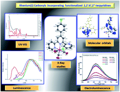
Several new rhenium(I) complexes [ReCl(CO)3(4′-R-terpy-κ2N)] incorporating 2,2′:6′,2′′-terpyridine-based ligands were successfully synthetized and characterized by IR, NMR (1H and 13C), UV-vis spectroscopy and single crystal X-ray analysis. The luminescent properties of [ReCl(CO)3(4′-R-terpy-κ2N)] were studied in solution and solid state, at 298 and 77 K. To better understand the photophysical properties of [ReCl(CO)3(4′-R-terpy-κ2N)], density functional theory (DFT) and time-dependent DFT (TD-DFT) calculations were performed. Preliminary studies towards application of these complexes in organic light emitting diodes (OLEDs) were carried out, including testing the possibility of electroluminescence intensity increase by including metallic nanowires in the structure design.
Herein, we present the synthesis, characterization and photophysical properties of six new Re(I) complexes incorporating 2,2′:6′,2′′-terpyridine ligand framework (Scheme 1). In particular, we aim to elucidate the possibility to tune the emission performance of Re(I)-terpyridine carbonyls by structural modifications of terpy ligand. 2,2′:6′,2′′-Terpyridine derivatives are noticeable ligands in coordination chemistry, but investigations of Re(I)-terpyridine carbonyls are scarce and the structure–property relationship remains unexplored.11 The paucity of data on Re(I)-terpyridine carbonyls can be attributed to the fact that [Re(CO)3(terpy)Cl], synthesized in 1988 by Juris and co-workers,12 was found to be nonluminescent in solution at room temperature. Recent studies, however, revealed the possibility of improving the emission performance of [ReCl(CO)3(4′-R-terpy-κ2N)] by structural modifications of terpy ligand and proved that Re(I) complexes incorporating 2,2′:6′,2′′-terpyridine ligand framework are suitable candidates for OLED materials.11c,13
The luminescent properties of [ReCl(CO)3(4′-R-terpy-κ2N)] were studied in solution and solid state, at 298 and 77 K. To get detailed insight into their electronic structure and spectroscopic properties, the density functional theory (DFT) and time-dependent DFT (TD-DFT) calculations were performed.
Silver nanowires (AgNWs) were synthesized using the polyol process, in which ethylene glycol (EG) served as the reducing and solvent reagent.15 The product was purified by centrifugation process and the mixture was diluted with isopropyl alcohol and centrifuged. The supernatant containing silver particles and unreacted substrates was removed. Finally the product was redispersed in 2 mL of pure water. Scanning electron microscopy yields diameters of the nanowires in the range from 50 to 150 nm, while their lengths range from 4 to even 30 microns.16 The samples for investigating the influence of silver nanowires on the electroluminescence properties of the devices were fabricated by placing the nanowires into PEDOT:PSS layer. The morphology of the samples were not substantially affected by the presence of the metallic nanoparticles.
1 | 3 | 4 | 6 | |
---|---|---|---|---|
Empirical formula | C30H19ClN3O3Re | C24H14Cl2N3O3Re | C24H14BrClN3O3Re | C26H20ClN4O3Re |
Formula weight | 691.13 | 649.48 | 693.94 | 658.11 |
Temperature [K] | 298.0(2) | 298.0(2) | 298.0(2) | 298.0(2) |
Wavelength [Å] | 0.71073 | 0.71073 | 0.71073 | 0.71073 |
Crystal system | Monoclinic | Monoclinic | Monoclinic | Triclinic |
Space group | P21/c | P21/c | P21/c | P |
Unit cell dimensions [Å, °] | a = 14.7833(3) | a = 9.4121(6) | a = 9.4203(6) | a = 7.2934(3) |
b = 11.8128(3) | b = 20.5407(9) | b = 20.6584(8) | b = 11.1958(6) | |
c = 30.1691(8) | c = 11.8912(7) | c = 11.8992(7) | c = 15.1296(6) | |
α = 91.434(4) | ||||
β = 100.552(2) | β = 104.084(6) | β = 104.218(6) | β = 92.141(3) | |
γ = 107.978(4) | ||||
Volume [Å3] | 5179.4(2) | 2229.8(2) | 2244.7(2) | 1173.40(9) |
Z | 8 | 4 | 4 | 2 |
Density (calculated) [Mg m−3] | 1.773 | 1.935 | 2.053 | 1.863 |
Absorption coefficient [mm−1] | 4.833 | 5.722 | 7.345 | 5.329 |
F(000) | 2688 | 1248 | 1320 | 640 |
Crystal size [mm] | 0.15 × 0.09 × 0.06 | 0.26 × 0.07 × 0.03 | 0.14 × 0.09 × 0.04 | 0.16 × 0.15 × 0.04 |
θ range for data collection [°] | 3.30 to 25.05 | 3.31 to 25.05 | 3.44 to 25.05 | 3.66 to 25.05 |
Index ranges | −17 ≤ h ≤ 17 | −11 ≤ h ≤ 11 | −8 ≤ h ≤ 11 | −8 ≤ h ≤ 8 |
−12 ≤ k ≤ 14 | −19 ≤ k ≤ 24 | −24 ≤ k ≤ 18 | −13 ≤ k ≤ 12 | |
−35 ≤ l ≤ 32 | −12 ≤ l ≤ 14 | −14 ≤ l ≤ 14 | −18 ≤ l ≤ 15 | |
Reflections collected | 30073 | 9767 | 9568 | 9547 |
Independent reflections | 9158 (Rint = 0.033) | 3933 (Rint = 0.040) | 3965 (Rint = 0.051) | 4145 (Rint = 0.0484) |
Completeness to 2θ = 50° [%] | 99.8 | 99.8 | 99.7 | 99.7 |
Max. and min. transmission | 1.000 and 0.630 | 1.000 and 0.455 | 1.000 and 0.085 | 1.000 and 0.582 |
Data/restraints/parameters | 9158/0/685 | 3933/0/298 | 3965/0/298 | 4145/0/318 |
Goodness-of-fit on F2 | 1.040 | 1.106 | 1.085 | 1.143 |
Final R indices [I > 2σ(I)] | R1 = 0.0266 | R1 = 0.0387 | R1 = 0.0451 | R1 = 0.0309 |
wR2 = 0.0512 | wR2 = 0.0677 | wR2 = 0.0971 | wR2 = 0.0646 | |
R indices (all data) | R1 = 0.0385 | R1 = 0.0540 | R1 = 0.0581 | R1 = 0.0409 |
wR2 = 0.0544 | wR2 = 0.0716 | wR2 = 0.1036 | wR2 = 0.0863 | |
Largest diff. peak and hole [eÅ−3] | 0.601 and −0.596 | 0.769 and −0.671 | 1.732 and −2.151 | 1.055 and −0.948 |
CCDC number | 1471443 | 1471444 | 1471445 | 1471446 |
Electrospray ionization mass spectrometry (ESI-MS) was performed on a Varian 500-MS IT Mass Spectrometer ion trap apparatus. The instrument was operating in the negative ion mode with a capillary voltage of 50 V, needle voltage of 5 kV and a spray shield voltage of 600 V. Drying gas (N2) temperature was 150 °C. High resolution mass spectrometry analyses were performed on a Waters Xevo G2 Q-TOF mass spectrometer (Waters Corporation) equipped with an ESI source operating in positive-ion modes. Full-scan MS data were collected from 100 to 1000 Da in positive ion mode with scan time of 0.1 s. To ensure accurate mass measurements, data were collected in centroid mode and mass was corrected during acquisition using leucine enkephalin solution as an external reference (Lock-Spray™), which generated reference ion at m/z 556.2771 Da ([M + H]+) in positive ESI mode. The accurate mass and composition for the molecular ion adducts were calculated using the MassLynx software (Waters) incorporated with the instrument.
Steady-state luminescence spectra of solid state and solution samples were measured with FLS-980 fluorescence spectrophotometer equipped with a 450 W Xe lamp and high-gain photomultiplier PMT + 500 nm (Hamamatsu, R928P) detector. The PL lifetime measurement was performed with a time correlated single photon counting (TCSPC) or multi-channel scaling (MCS) method. Excitation wavelength (375 nm or 470 nm) for TCSPC was obtained using the TCSPC diode with various pulse periods as light source. For MCS excitation wavelength was obtained using 60 W microsecond Xe flash lamp.
Photoluminescence spectra in solid state as film deposited on glass substrate and as blends with poly(N-vinylcarbazole) (PVK) on glass substrate were registered using Hitachi F-2500 spectrometer. In order to collect electroluminescence (EL) spectra the voltage was applied using a precise voltage supply (Gw Instek PSP-405) and the sample was fixed to an XYZ stage. Light from the OLED device was collected through a 30 mm lens, focused on the entrance slit (50 μm) of a monochromator (Shamrock SR-303i) and detected using a CCD detector (Andor iDus 12305). Typical acquisition times were equal to 10 seconds. The pre-alignment of the setup was done using a 405 nm laser. Differential Scanning Calorimetry (DSC) was performed with a TA-DSC 2010 apparatus, under nitrogen atmosphere using sealed aluminum pans with heating rate 20 °C min−1. Electrochemical measurements were carried out using ATLAS 0531 Electrochemical Unit & Impedance Analyzer potentiostat. Cyclic voltammetry experiments were conducted in acetonitrile (Aldrich, HPLC grade) and 0.2 M tetrabutylammonium hexafluorophosphate (Bu4NPF6 Aldrich, 99%) was used as the supporting electrolyte. Pt electrode, platinum coil and a quasi-Ag/AgCl electrode served as working, auxiliary and reference electrode, respectively. Potentials were referenced with respect to ferrocene (Fc), which was used as the internal standard. The HOMO and LUMO levels were calculated by assuming the absolute energy level of Fc/Fc+ as −5.1 eV to vacuum. Active layers thickness was measured by atomic force microscopy (AFM) Topometrix Explorer TMX 2000.
The presence of three intense ν(CO) bands in the region 2023–1873 cm−1 is consistent with a facial arrangement of the carbonyl groups and indicates bidentate chelate coordination of 4′-R-terpy ligand in 1–6. Medium intensity absorptions associated with the stretching modes ν(CN), ν(CC) modes of the 4′-R-terpy ligand occur in the range 1617–1512 cm−1.22
The unsymmetrical bidentate coordination mode of 4′-R-terpy in the examined complexes is also evidenced by NMR data as the resonances attributed to the terminal pyridine protons are clearly differentiated in both 1H and 13C NMR spectra.
Fig. 1 A perspective views showing the asymmetric units of 1, 3, 4 and 6 together with the atom numbering. Displacement ellipsoids are drawn at 50% probability. |
In [ReCl(CO)3(4′-R-terpy-κ2N)] complexes, the Re(I) is six-coordinated in a distorted octahedral geometry defined by three facially arranged carbonyl ligands, two nitrogen atoms from two pyridine rings of the 4′-R-terpy ligand and chlorine atom. The major angular distortion from the idealized octahedral geometry is attributed to geometrical constraints issued from the occurrence of five-member chelate ring of the bidentate 4′-R-terpy ligand, resulting in N(2)–Re(1)–N(1) angle of 77.61(11)° for 1, 74.97(19)° for 3, 75.0(2)° for 4 and 74.03(19)° for 6 (Table S1†). The bidentate 4′-R-terpy ligand as a whole is far from planarity. The dihedral angle between the mean planes of two coordinated pyridine rings is 10.75(1)° in molecule A and 12.80(4)° in molecule B of 1, 5.42(7)° in 3, 6.30(6)° in 4 and 15.91(5)° in 6, whereas the uncoordinated pyridyl ring and R substituent in the 4′-terpy position are inclined to the central pyridine at 53.42(1) and 22.63(6)° in molecule A and 67.09(6)° and 15.40(5)° in molecule B of 1, 61.84(8)° and 19.89(1)° in 3, 60.88(2)° and 18.94(1)° in 4, 50.02(8)° and 19.46(8) in 6, respectively.
The Re–C bond distances of 1, 3, 4, and 6 compare well to the values reported for complexes [Re(CO)3La(N–N)]n+ with facially arranged carbonyl ligands.11a–f The Re(1)–N(2) bond length is significantly longer than Re(1)–N(1), which seems to be a feature typical for structures involving bidentate terpy ligands.11c–f In contrast, in the complexes incorporating tridentate-coordinated terpy ligand [ReCl(CO)2(4′-R-terpy-κ3N)], the metal-nitrogen distance to the central ring is shorter than the corresponding distances to the outer pyridyl rings.11a,b The elongation of the Re(1)–N(2) distance in [ReCl(CO)3(4′-R-terpy-κ2N)] is attributed to the steric bulk of the uncoordinated pyridyl ring. The steric hindrance induced by uncoordinated pyridyl ring is also responsible for the enlargement of the C(1)–Re(1)–N(2) angle (101.97(14)–103.2(2)°), which is the largest one between any two cis-located ligands (Table S1†).
Compound | Medium | λ/nm (103 × ε/dm3 mol−1 cm−1) |
---|---|---|
1 | CHCl3 | 389.8 (6.1), 317.1 (30.4), 285.2 (24.9) |
MeCN | 383.9 (8.7), 315.0 (37.9), 278.6 (28.4), 191.49 (126.9) | |
Film | 393, 320 sh | |
Blend | 344, 330 | |
2 | CHCl3 | 383.9 (9), 306.1 (23.4), 240.9 (39.3) |
MeCN | 374.0 (42.3), 306.0 (90.7), 230.7 (184), 206.35 (235.1) | |
Film | 398, 315 sh | |
Blend | 389, 345, 330 | |
3 | CHCl3 | 398.6 (4.0), 303.0 (25.1), 267.6 (23.4) |
MeCN | 385.4 (3.3), 284.9 (19.6), 264.0 (18.2), 196.6 (178.2) | |
Blend | 345, 330 | |
4 | CHCl3 | 401.2 (4.8), 304.2 (30.2), 267.9 (27.1) |
MeCN | 385.4 (5.4), 294.5 (32.5), 264.7 (30.8), 194.5 (71.8) | |
Blend | 344, 330 | |
5 | CHCl3 | 399.2 (6.5), 299.9 (35.3), 261.4 (43.3) |
MeCN | 383.2 (9.5), 300.5 (46.5), 260.1 (60.9), 197.4 (125.8) | |
Blend | 345, 330 | |
6 | CHCl3 | 429.8 (14.4), 380.2 (8.2) sh, 312.6 (14.7), 247.2 (17.1) |
MeCN | 419.2 (16.5), 354.1 (9.3), 308.7 (14.2), 246.2 (17.7), 192.2 (178.2) |
The electronic absorption spectra of 1–6 in acetonitrile (10−5 M), plotted as a function of molar extinction coefficient versus wavelength, are shown in Fig. 2. The dominant absorption bands of 1–6 with molar extinction coefficients on the order of 1.42–23.51 × 10⁴ M−1 cm−1 in the range 200–330 nm can be assigned to the spin allowed intraligand (IL) π → π* transitions of the diimine moiety. These bands are accompanied by the lower-energy absorptions, which are tentatively attributed to the metal-to-ligand transitions (1MLCT). Lower molar extinction coefficients (0.33–4.23 × 10⁴ M−1 cm−1) and wide breadth of these bands are consistent with this assignment. Furthermore, as expected for 1MLCT bands, the longest wavelength absorption band of [ReCl(CO)3(4′-R-terpy-κ2N)] in chloroform is red-shifted by 5.9 nm for 1, 9.9 nm for 2, 13.2 nm for 3, 15.8 nm for 4, 16 nm for 5 and 10.6 nm for 6 with reference to more polar acetonitrile solution. From Table 2 and Fig. 2, it can also be noted that the absorption spectra of [ReCl(CO)3(4′-R-terpy-κ2N)] are clearly affected by the strong electron-donating substituents R introduced into 4′-position of the terpy ring. For complex 2, the substituent 4-methoxynaphthalen-1-yl draws electron density from the 2,2′:6′,2′′-terpyridine, facilitating the photoinduced metal-to-ligand charge transfer. It manifests itself in significant increase of the intensity of the longest wavelength absorption band of 2 compared to other studied complexes. In turn, introduction of strong electron-donating dimethylamine group in 6 results in both intensity increase and clear red-shift of the absorption in acetonitrile compared to 3, 4 and 5, while the energy of the low-energy band of [ReCl(CO)3(4′-R-terpy-κ2N)] containing chloro, bromo and fluoro substituents R remains nearly unchanged. For compounds 2 and 6, the lower-energy absorption is probably attributed to intraligand charge transfer transitions (ILCT) occurring from electron-donating substituent R to terpy moiety.25
In the UV-vis spectra of the investigated compounds in solid state, that is, as thin film on glass substrate two absorption band are seen in the similar range as were observed in chloroform solution. In the case of blend with poly(9-vinylcarbazole) (PVK) (15 wt% of compound in PVK) absorption typical for matrix is dominated. The absorption band in the lowest energy region is not clearly pronounced, except of 2.
In order to get more insight into the nature of the electronic transitions involved in the absorption processes, computational studies at DFT/B3LYP/DEF2-TZVPD/6-31+G* level were undertaken. As shown in Table S1,† the predicted bond lengths and angles of 1, 3, 4 and 6 are in good agreement with the values based upon the X-ray crystal structure data, as well as the general trends observed in the experimental data are well reproduced in the calculations, providing confidence on the reliability of the chosen method to reproduce the geometries of the studied complexes.
Schematic representation of molecular orbital (MO) energy levels is presented in Fig. 3, whereas the contours of the frontier molecular orbitals of 1–6 are depicted in Fig. 4. The percentage contributions of Re, CO, terpy ring, R substituent and Cl fragments into the selected molecular orbitals of 1–6 are summarized in Tables S3–S8 (ESI† Materials).
As can be seen in Fig. 3, the HOMO level of 2 and 6 is clearly destabilized in comparison with other studied complexes, whereas the substituents R1, R3, R4 and R5 introduced into terpy ring seem to have almost the same impact on the energy of the highest molecular orbital of [ReCl(CO)3(4′-R-terpy-κ2N)]. The LUMO energy of 1–6 is only marginally influenced by the substituents attached to 2,2′:6′,2′′-terpyridine. As a result, the HOMO–LUMO gap is significantly lower in 2 (3.21 eV) and 6 (2.90 eV) compared to the other studied complexes. Notably, the HOMO–LUMO gap of 1, 3, 4 and 5 was found to lie in a narrow range of 3.57 eV to 3.59 eV. In case of complex 1, the HOMO–LUMO difference energy remains comparable to the energy gap in the complexes 3, 4 and 5, although HOMO orbitals is considerably localized on R substituent and it has to a large extend πR character.
As can be seen from Tables S3–S8,† the LUMOs of 1–6 have similar distribution and they are predominantly composed of π* orbitals localized on the terpyridine moiety with percentage participation of 74.63% for 1, 73.95% for 2, 74.74% for 3, 74.66% for 4, 74.01% for 5 and 76.12% for 6. These orbitals also are contributed by 5d(Re) and π* orbitals of the R substituent, but to a much smaller extent.
For complexes 3, 4 and 5, the HOMO and HOMO−1 orbitals are constituted by 5dyz and 5dxz rhenium orbitals (∼45%) in bonding relation to the carbonyl π* orbitals (∼27%) and antibonding arrangement to chlorine p orbitals (∼22%). The HOMO−2 of these compounds is composed of 5dxy rhenium orbital (∼55%) and carbonyl π* orbitals (∼32%).
Attached to the terpy ring, biphenyl-4-yl (R1), 4-methoxynaphthalen-1-yl (R2) and 4-dimethylaminophenyl (R6) substituents raise the energy of 4′-R-terpy-localized orbitals. Consequently, the HOMOs of 1, 2 and 6 are essentially π orbitals on the 4′-R-terpy ligand and they are predominately localized on the R substituent – 57.11% for 1, 84.97% for 2 and 81.84% for 6. The orbitals 5dπ(Re), π*(CO) and 2pπ(Cl) mainly contribute to HOMO−1 and HOMO−2, while and HOMO−3 has d(Re)/π*(CO) character. For complex 1, 5dπ(Re) and π*(CO) orbitals also participate in the HOMOs of 1 – 16.17% (5dπ(Re)) and 9.46% (π*(CO)).
For complexes 3, 4, 5, π orbital of 4′-R-terpy lies below MOs with the large participation of d orbitals of rhenium. Differences in the energy order of the π orbital and d based orbitals is clearly visible amongst the value of the energy gap between the HOMO and LUMO orbitals for respective complexes (Fig. 3).
The influence of the basis sets on the energetics of MOs was tested with using larger basis sets TZVP, def2-TZVPD, TZ2P in calculations for complexes 2, 3 and 6. The most essential results obtained from this part of calculations are collected in the Tables S9 and S10† and shown in the Fig. S3 in ESI† materials. In the Fig. S3,† the energy diagram of frontier MOs of 2, 3 and 6 species, calculated using four different bases, is presented. Comparison of MOs energy indicates that the tested basis sets have very little effect on energy order and the nature of highest occupied and lowest unoccupied molecular orbitals. In the calculations with TZVP and def2-TZVPD basis sets, energy gap for the complexes 2 and 6 are slightly higher compared to the calculations with the def2-TZVPD/6-31+G* basis. For these two larger basis sets, energy gap increases by approximately 0.09 eV and 0.04 eV for 2 and 6, respectively. For complex 3, this gap reduces by about 0.16 eV compared to the results of calculation in the def2-TZVPD/6-31+G* basis set. Composition of the frontier molecular orbitals for complexes 2, 3 and 6 obtained from the calculations in TZVP and def2-TZVPD basis sets is also very similar to the results of calculations in the def2-TZVPD/6-31+G* basis (Table S9 in ESI† materials). Also in the calculation with the TZ2P basis set and the ZORA relativistic approximation, no significant changes in the properties of HOMOs and LUMOs orbitals were observed compared to remaining bases (Table S10†).
In aromatic species chemistry, split degenerated π orbitals of aromatic ring under the influence of substituent with the electronegative atom is known. Such a split increases the energy of one HOMO π orbitals as a result of the formation the antibonding combination between π orbital of aromatic system and the p orbital of electronegative atom in a substituent. Degree of such a split can be approximately correlated with the electro-donating properties of the substituent, for example the split is smaller in case of chlorine, bromine and larger in case of such substituents like –OH, –NH2 or –N(CH3)2. In relation to the presented computational results, one could suggest that a similar effect is visible in the case of π orbitals of the 4′-R-terpy ligand with the substituents R2 and R6. In these two complexes (2 and 6), HOMO orbital is characterized by a predominating contribution coming from the πR orbital. On the other hand, it cannot be excluded that the energy of this HOMO orbital is an overestimate. Perhaps its energy should be lower and be within the range of d based MOs energy.
The experimental and calculated electronic absorption spectra of 1–6 are compared in Fig. 5. The excited states calculated for 1–6 (Tables S11–S16†) demonstrated that excited-state electronic structures are best described in terms of multiconfigurations, wherein a linear combination of several occupied-to-virtual MO excitations comprises a given optical absorption band. The lowest energy absorption band of 1–6 is generally attributed to a few allowed electronic transitions corresponding one-electron excitations H → L and H−2 → L for 1, H → L, H → L+1 for 2 and 6, H−3 → L, H−1 → L for 3, H−3 → L, H−1 → L and H−1 → L+1 for 4, H−1 → L for 5.
Fig. 5 Experimental (black) and calculated (red) electronic absorption spectra of 1–6 in MeCN solution. |
Interestingly, the low-wavelength range of theoretical absorption spectrum of 2 and 6 is dominated by intense transitions, mainly of ILCT (πR/terpy → ) character. Especially for complex 6, the S1 excited state corresponds to the very intensive electronic transition between π orbitals of the ligand 4′-R6-terpy. For complexes 1, 3, 4 and 5 lowest excited state has basically d → character and is of MLCT type. In regard of differences in the description of the electronic structure of investigated complexes, the influence of the functionals and the basis sets on the calculation results were taken into account. For complex 6, additional test calculations were performed with the use of different functionals, i.e. hybrid-GGA, pure GGA, and long range corrected (Table S17 in ESI†). For all tested functionals, the lowest electronic transitions S1 are of ILCT character, and calculated oscillator strengths of these transitions are significantly larger (0.18–0.94 a.u.) compared to oscillator strengths of S2 transitions being basically of MLCT type (0.007–0.448 a.u.). Among applied functionals, the smallest difference of the energy between the lowest experimental band and the calculated S1 transitions, is obtained in calculations with B3LYP functional (0.42 eV) providing confidence on the reliability of the chosen method to reproduce the spectral features of the studied complexes.
Inspection of the orbital percentage composition, oscillator strengths and major contributions of transitions assigned to the low-energy absorption band of 1, 3, 4 and 5 (Fig. 4 and Tables S3–S8†) demonstrates that these absorption bands have a mixed character 1MLCT/1LLCT/1ILCT/1IL, but the balance between 1MLCT/1LLCT and 1ILCT/1IL is clearly shifted toward the former.
Compound (R) | Medium | λex [nm] | λem [nm] | Stokes shift [cm−1] | ϕ [%] | τ, ns (weight) | χ2 |
---|---|---|---|---|---|---|---|
a (4:1 v/v). | |||||||
CHCl3 | 392 | 664 | 10450 | 0.52 | 3.67 (93.89%), 32.77 (6.11%) | 1.137 | |
MeCN | 366 | 442, 671 | 4698, 12194 | 0.47 | 4.46 (52.20%), 1.57 (47.80%) for λem = 442 nm; 2.94 (60.41%), 1.75 (39.59%) for λem = 671 nm | 1.208; 1.124 | |
Solid | 462 | 592 | 4753 | 12.46 | 494.42 | 1.049 | |
EtOH–MeOHa (77 K) | 263, 306, 363 | 516, 550 | 8168 | 88506.6 (66.94%), 12857.7 (33.06%) | 1.039 | ||
Film | 330 | 395, 587 | |||||
390 | 440, 584 | ||||||
Blend | 330 | 380, 580 | |||||
390 | 440 | ||||||
CHCl3 | 384 | 658 | 10844 | 0.35 | 4.38 | 1.088 | |
MeCN | 375 | 650 | 11282 | 0.53 | 4.77 (83.09%), 0.66 (16.91%) | 1.047 | |
Solid | 471 | 574 | 3810 | 1.18 | 9539.0 (87.12%), 2402.9 (12.88%) | 1.072 | |
EtOH–MeOHa (77 K) | 264, 316, 389 | 536, 568 | 7050 | 465271.6 (77.26%), 144424.4 (22.74%) | 1.109 | ||
Film | 330 | 375, 409, 580 | |||||
390 | 438, 467, 585 | ||||||
Blend | 330 | 377, 570 | |||||
390 | 442, 467 | ||||||
CHCl3 | 397 | 669 | 10241 | 0.13 | 3.03 (91.19%), 17.99 (8.81%) | 1.063 | |
MeCN | 376 | 664 | 11536 | 0.09 | 2.12 (86.66%), 5.61 (13.34%) | 1.120 | |
Solid | 475 | 591 | 4132 | 21.00 | 493.10 | 1.060 | |
EtOH–MeOHa (77 K) | 264, 305, 335, 365 | 542 | 8947 | 5520 (66.83%), 1903 (33.17%) | 1.047 | ||
Blend | 330 | 375, 577 | |||||
390 | 414, 538 | ||||||
CHCl3 | 396 | 665 | 10215 | 0.44 | 2.94 (63.71%), 71.60 (36.29%) | 1.134 | |
MeCN | 376 | 664 | 11536 | 0.15 | 2.21 (87.33%), 12.91 (12.67%) | 1.158 | |
Solid | 479 | 592 | 3985 | 16.93 | 425.34 | 1.077 | |
EtOH–MeOHa (77 K) | 267, 304, 333, 365 | 551 | 9248 | 5110 (75.16%), 1805 (24.84%) | 1.035 | ||
Blend | 330 | 375, 579 | |||||
390 | 411, 436, 568 | ||||||
CHCl3 | 397 | 676 | 10396 | 0.40 | 2.72 | 1.092 | |
MeCN | 380 | 516, 666 | 6936, 11301 | 0.27 | 3.22 for λem = 516 nm; 2.36 for λem = 666 nm | 1.109; 0.983 | |
Solid | 489 | 640 | 4825 | 0.96 | 13.43 (82.87%), 57.35 (17.13%) | 1.066 | |
EtOH–MeOHa (77 K) | 268, 298, 331, 370 | 549 | 8812 | 3906.3 | 1.006 | ||
Blend | 330 | 377, 576 | |||||
390 | 438, 465 | ||||||
CHCl3 | 421 | 636 | 8030 | 1.13 | 22.54 (84.36%), 7.11 (15.64%) | 1.100 | |
MeCN | 452 | 687 | 7568 | 1.91 | 0.18 (96.30%), 2.48 (3.70%) | 1.037 | |
Solid | 494 | 636 | 4520 | 0.67 | 281.68 (61.85%), 3081.25 (38.15%) | 1.192 | |
EtOH–MeOHa (77 K) | 312, 325, 368, 444 | 580 | 5281 | 263293.5 (77.92%), 103380.6 (22.08%) | 1.056 |
In solution, the complexes [ReCl(CO)3(4′-R-terpy-κ2N)] are weakly emissive. The average lifetimes and quantum yields ϕ fall in the regions 0.26–27.86 ns and 0.09–1.91%, respectively. Excitation of [ReCl(CO)3(4′-R-terpy-κ2N)] at the HOMO → LUMO absorption band gave rise to well-separated dual emission, with maxima at 442 and 671 nm for 1 in MeCN, 516 and 666 nm for 5 in MeCN, or broad structure-less emission band in the range 636–687 nm for other studied complexes. With reference to the photophysical studies of related tricarbonylrhenium(I) polypyridine systems, the emission in the range 636–687 nm seems to be consistent with the metal-ligand-to-ligand charge transfer phosphorescence (3MLLCT), while the higher energy emission peaks (442 and 516 nm) may be tentatively assigned to the 3LC (π → π*) exited state.9e,11b,12,26 The free ligands display fluorescence at 359 nm for 4′-R1-terpy and 437 nm for 4′-R5-terpy, ruling out the possibility that any of the emissions originate from ligand impurities.
As can be seen from Table 3, the emission of 6 was found to be significantly red-shifted with increasing solvent polarity. It appeared at ∼50 nm longer in wavelength as the polarity of the solvent increased from chloroform to acetonitrile. Such a behaviour is consistent with 4′-R-terpy-centred excited state with significant contributing CT character.27 In contrast, the emission maxima of the other studied complexes are influenced only marginally by changes in solvent polarity. A slight negative solvatochromic effect, reflected in blue-shifted emission with increasing solvent polarity, can be noticed for 2 and 3.
In low-temperature 77 K EtOH–MeOH (4:1 v/v) glassy medium, the emission bands of the complexes occurred at higher energy (516–580 nm) owing to the rigidochromic effect, which is responsible for raising the energy of the emissive 3MLLCT due to the lack of solvent reorganization following excitation.1,11c,28 Upon cooling to low temperature (77 K), the complexes 3, 4, and 5 exhibit broad and unstructured emission, which is a characteristic feature of MLCT emission. The microsecond excited state lifetimes support the phosphorescence assignment. The emissive bands of 1, 2 and 6 show the appearance of partial vibronic coupling features, indicating some degree of mixing between 3MLLCT and 3LC states.
All the examined complexes are also emissive in solid state. In similarity with frozen matrix, the emissions of 1–6 appear at lower energy relative to that reported for solution, consistent with the rigidochromic effect. Most notably, the introduction of biphenyl-4-yl (R1), 4-chlorophenyl (R3) and 4-bromophenyl (R4) substituents into the terpy ring leads to a significant increase in quantum yield ϕ: 12.46% for 1, 21.00% for 3 and 16.93% for 4. The stronger emission in solid than that in solution may be attributed the aggregation of the complexes due to intermolecular π–π interactions between the adjacent molecules in the crystal lattice. As a result, the triplet energy level of the charge transfer state from Re(I) to the interacting ligands is reduced and the ligands participate in the excited state in the solid state. In addition, the rotation of the free pyridine and substituent rings were also limited.
Triplet excited states of [ReCl(CO)3(4′-R-terpy-κ2N)] were also investigated computationally at DFT/UB3LYP/def2-TZVPD/6-31+G* level. The energies of phosphorescence emissions for [ReCl(CO)3(4′-R-terpy-κ2N)] were calculated from the energy difference between the ground singlet and the triplet state ΔET1−S0 as well as they were computed using TD-DFT. The calculated values of phosphorescence emission energy together with a description of character of the triplet states and experimental data are gathered in Table 4. Isosurfaces of the difference between α and β spin densities for [ReCl(CO)3(4′-R-terpy-κ2N)] at its T1 state are presented in Fig. 7 as well as the HSOMO and LSOMO involved in TD-DFT triplet excitations are available in ESI (Fig. S5†). Taken into consideration that calculated emission energies are in reasonably good agreement with the experimental emission band maxima of 1–6, it is possible to conclude that luminescence has character of the phosphorescence and occurs from the low-lying triplet state (T1). Theoretical calculations predicted mixing between 3MLCT, 3LLCT, 3ILCT and 3IL excitations in the lowest excited states of 1–6. The complexity of the triplet state character results from the complicated electron structure of excited states of such complexes, in which electron excitations involve both d orbitals of metal and the π orbitals of ligand 4′-R-terpy. For complexes 1, 2 and 6, however, the lowest triplet state seems to be mainly of 3ILCT type, while 3MLCT character dominates in T1 for remaining complexes.
Compound | DFT | TD-DFT | λexp [nm eV−1] | ||||
---|---|---|---|---|---|---|---|
ΔET1−S0 (eV)/(nm) | Character | Major contribution (CI coefficient) | E [eV] | λcal [nm] | Character | ||
a ΔET1−S0-energy difference between the ground singlet and triplet states. | |||||||
1 | 2.08/596.4 | 3ILCT/3IL/3MLCT/3LLCT | H → L (0.6414) | 1.89 | 656.30 | 3ILCT/3IL/3MLCT | 671/1.85 |
2 | 1.93/642.0 | 3ILCT/3IL/3LLCT/3MLCT | H → L (0.6094) | 1.76 | 706.21 | 3ILCT/3IL | 650/1.91 |
3 | 1.81/685.7 | 3MLCT/3LLCT/3ILCT/3IL | H → L (−0.6790) | 1.82 | 679.89 | 3MLCT/3LLCT/3IL | 664/1.87 |
4 | 1.77/700.2 | 3MLCT/3LLCT/3ILCT/3IL | H → L (−0.6790) | 1.82 | 682.11 | 3MLCT/3LLCT/3IL | 664/1.87 |
5 | 1.74/711.3 | 3MLCT/3LLCT/3ILCT/3IL | H → L (0.6883) | 1.83 | 678.56 | 3MLCT/3LLCT/3IL | 666/1.86 |
6 | 1.87/662.6 | 3ILCT/3IL/3LLCT/3MLCT | H → L (0.6769) | 1.81 | 684.99 | 3ILCT/3IL | 687/1.80 |
Fig. 7 Isodensity surface electron spin density for the complexes 1–6 at their T1 state geometry. Blue and green colours show regions of positive and negative spin density values, respectively. |
The emission ability of the compounds in the form of film and blend was examined under two excitation wavelengths, in the maximum of the absorption band, that is, 330 and 390 nm. The exemplary emission spectra of 5 in the film and blend are presented in Fig. 8. In the PL spectra of the compounds in thin film on glass two emission bands are seen under both applied λex (330 and 390 nm). In the case of compounds molecularly dispersed in a PVK matrix the lack of emission at lower energetic region under λex = 390 nm was observed. Additionally, taking onto account the fact that the emission spectrum of the host significantly overlaps with the guest's UV-vis spectrum (cf. Fig. 8a) it can be supposed that Förster Resonance Energy Transfer (FRET) takes place. Similar behavior was found in the case of the Re(I) complex reported in our former article.13b Thus, PVK matrix served both as a hole transport material and as an energy donor.
Fig. 8 (a) UV-vis absorption spectra of compound 1, compound 1 in blend with PVK and PL spectrum of PVK; (b) PL spectra of 1 in film and blend with PVK. |
Code | Eox1 [V] | Eox2 [V] | Epc − Epa [V] | Eox,onset [V] | Ered1 [V] | Epc − Epa [V] | Ered2 [V] | Ered,onset [V] | HOMO [eV] | LUMO [eV] | Eg [eV] |
---|---|---|---|---|---|---|---|---|---|---|---|
a HOMO = −5.1 − Eox,onset, LUMO = −5.1 − Ered,onset, Eg = Eox,onset − Ered,onset = HOMO − LUMO. | |||||||||||
1 | 0.76 | — | — | 0.60 | −1.76 | 0.07 | — | −1.63 | −5.70 | −3.47 | 2.23 |
2 | 0.72 | — | — | 0.59 | −1.83 | 0.09 | — | −1.70 | −5.69 | −3.40 | 2.29 |
3 | 0.75 | 1.12 | 0.14 | 0.59 | −1.75 | 0.08 | −2.23 | −1.63 | −5.69 | −3.47 | 2.22 |
4 | 0.77 | 1.31 | — | 0.66 | −1.70 | 0.06 | — | −1.50 | −5.76 | −3.60 | 2.16 |
5 | 0.77 | 1.21 | 0.16 | 0.60 | −1.78 | 0.09 | −2.35 | −1.65 | −5.70 | −3.45 | 2.25 |
Fig. 9 Cyclic voltammograms of compound 2 and 3 (scan rate 10 mV s−1, electrolyte 0.2 M Bu4NPF6 in acetonitrile). |
The appropriate alignment of the energy levels between the host matrix and the guest molecules is fulfilled for obtained compounds. Comparing the HOMO and LUMO energy of the compounds (HOMO ca. −5.7 eV, LUMO ca. 3.5 eV) and PVK (HOMO −5.8 eV and LUMO 2.2 eV) it is evident that the guest possess HOMO and LUMO energy higher and lower, respectively, than the energy levels of a matrix. OLEDs with configuration ITO/PEDOT:PSS/PVK:compound/Al were fabricated. Additionally, devices in which compounds 2 and 3 formed an emitting single layer were obtained (ITO/PEDOT:PSS/compound 2 or 3/Al). The morphology of the active layer, as another key factor for the OLEDs functioning, was investigated by atomic force microscopy (AFM) and the exemplary AFM images for PVK doped with compound 3 are shown in Fig. S6.† The AFM images of blends show uniform and flat surfaces, indicating good film-forming properties. The surface root-mean-square roughness (RMS) of these layers were in the range of 22.8–0.7 nm. The current density–voltage (J–V) characteristics of the prepared devices were registered and the exemplary J–V plot is depicted in Fig. 10a, whereas the obtained data for all devices are summarized in Table 6. The turn-on voltage (Von) of all devices was about 3.5 V, except for the one based on compound 2 applied as single emitting layer. However, the OLEDs differ in value of current density (J). The significant increase in the reached J was found after utilization of PVK doped with the compounds in comparison with a neat film of 1 and 2. The lowest value of J exhibited device containing complex 3. For the devices containing compounds dispersed in matrix the electroluminescence (EL) spectra were registered and the exemplary spectra are presented in Fig. 10b together with intensity dependencies on the applied external voltage (Fig. 10c). EL spectrum becomes fully dominated by the dye emission. The EL spectra measured for all compounds match the photoluminescence spectra rather well, and we observe some variation regarding both the energetic position of the EL bands as well as their shapes. The maximum of the EL bands shifts towards longer wavelengths. In all of the compounds the emergence of EL signal was observed between 15 V and 26 V. In the case of ITO/PEDOT:PSS/PVK:2/Al (Fig. 10c) and ITO/PEDOT:PSS/PVK:3/Al the experiment was carried out in such a way that the external voltage was first ramped up and then decreased. It should be noted that in this article OLEDs with the simplest structure are presented. It is well known that the device performance can be improved by introducing additional charge transporting layers such as carrier injection and charge transporting layers. However, in our investigations another possibility of EL emission enhancement was applied by incorporating silver nanowires (AgNWs) into PEDOT:PSS layer. Thus, the devices with the following structure ITO/PEDOT:PSS:AgNWs/PVK:5/Al were prepared. The comparison between J–V characteristics and EL spectra measured for the compound 5 with and without the nanowires incorporated to the PEDOT:PSS layer is displayed in Fig. 11. There are two remarkable observations that can be ascribed to the effects caused by silver nanowires. First of all, the emergence of the EL spectrum occurs significantly faster in the case of plasmonic structure: the spectrum appears at external voltage of 13–15 V as compared to around 19 V for the device devoid of silver nanowires. It indicates that the efficiency of carrier generation and injection is considerably higher when silver nanowires are incorporated into the structure. Furthermore, the observed intensities differ considerably between the two structures, and the difference is approximately an order of magnitude of comparable external voltages. This result indicates that it is possible not only to increase absorption with metallic nanoparticles,32 but also influence the EL response of the actual device.
Code | Active layer | J [mA cm−2] | Von [V] | λEL [nm] | Active layer thickness [nm] | RMS [nm] |
---|---|---|---|---|---|---|
1 | Film | 0.05 | 3.5 | — | — | — |
Blend | 29 | 3.5 | 630 | 135 | 11.6 | |
2 | Film | 0.77 | 2.4 | — | — | — |
Blend | 44 | 3.5 | 615 | 130 | 22.8 | |
3 | Blend | 5.3 | 3.2 | 635 | 150 | 0.70 |
4 | Blend | 20 | 3 | 625 | 140 | 7.70 |
5 | Blend | 20 | 3.5 | 630 | 158 | 1.83 |
Footnote |
† Electronic supplementary information (ESI) available: Short intra- and intermolecular contacts, MO composition of selected compounds, calculated absorption and emission data, excitation and emission spectra with PL lifetime curves, DSC thermograms of 2 and AFM images of the blend PVK with 3. CCDC 1471443–1471446. For ESI and crystallographic data in CIF or other electronic format see DOI: 10.1039/c6ra08981j |
This journal is © The Royal Society of Chemistry 2016 |