DOI:
10.1039/C6RA08903H
(Paper)
RSC Adv., 2016,
6, 58764-58770
Facile preparation of N,S-doped hierarchical porous carbons based on 3-aminophenol-3-mercaptophenol co-resins for supercapacitor applications†
Received
7th April 2016
, Accepted 28th May 2016
First published on 1st June 2016
Abstract
Hierarchical porosity and heteroatom-doping have been proved to be desirable for carbon electrode materials in advanced supercapacitors. In this study, dual N,S-doped hierarchical carbon materials were facilely prepared via a simple carbonization of the potassium salts of 3-aminophenol-3-mercaptophenol co-resin. The morphology, structure and surface properties of the carbon materials were investigated using scanning electron microscopy (SEM), transmission electron microscopy (TEM), N2 adsorption, X-ray photoelectron spectroscopy (XPS), and energy dispersive spectroscopy (EDS). It is proposed that the fast nucleophilic addition between the phenols and formaldehyde produces nano-sized gel particles, followed by carbonization into carbon particles, finally packing to the mesopores. The in situ activation of potassium ions creates abundant ultra-microporosity. Due to the synergistic effects of the tailored porosity and N,S,O-doping, the prepared carbons show a high specific capacitance (252 F g−1 for NSHPC-700), good capacitance retention (63.3% for NSHPC-900) in the range of 0.2–20 A g−1 and very low relaxation time constant of 0.16 s in a KOH electrolyte.
Introduction
The rapidly growing markets of renewable energy sources and commercial electrical devices evoke a great demand for novel energy storage systems that can provide higher energy and power than traditional systems. Carbon-based supercapacitors, generally called electrochemical double layer (EDL) capacitors, have received tremendous interest and attention as promising systems for power-based applications.1 Among various carbon materials, porous carbon materials have been widely used due to their low cost, large surface area, tuneable pore structure, uniform and adjustable pore size, chemically inert nature, mechanical stability, and good conductivity.2–6
The porosity characteristics of porous carbon materials, mainly the specific surface area, pore size and its distributions, determine their EDL capacitor performance (specific capacitance, power and energy density).7 Clearly, the meso/macropores are desirable for high power performance because the electrolyte ions can diffuse rapidly in these pores. According to the equation of C = εA/d,8 the energy stored in supercapacitor is linearly proportional to the specific surface area of the porous carbons (A) and is inversely proportional to the space between pore wall and the ion (d). It is clear that for high capacitance (or high energy density), the micropores of the carbon electrodes are optimal due to their high specific surface area and minimal space. Many experimental results have pointed out the importance of microporosity, especially the ultra-micropores of carbon electrode materials in advanced supercapacitors.7,9–14 In this sense, hierarchical porous carbon materials have been proved to possess distinctive potential for high performance supercapacitor applications because their well-defined hierarchical porosity can effectively concert each pore level during the charge/discharge process.15–21 In general, a two-step method is usually adopted to construct hierarchical porosity. For mesoporosity, some templates with a special nanostructure (e.g. porous silica oxide or metal oxide)5,19,22,23 or molecular structure (e.g. triblock copolymer F127)18,24 are needed. For microporosity, a post-activation process is usually conducted.18,19 Yuan and co-workers prepared hierarchical porous carbon materials via a one-step method based on a soft template method in which the microporosity resulted from the removal of polyethylene oxide (PEO) segments of triblock copolymer embedded into the resins.25 Hierarchical mesoporous carbon materials with large microporosity can also be directly prepared via tri-constituent co-assembly with the use of resols as the carbon precursor, tetraethyl orthosilicate as the inorganic precursor and triblock copolymer F127 as the soft template.26 The templates are usually prepared via a complicated and time-consuming process and some have not been put into mass production. These deficiencies strongly limit their potential in commercial applications. Therefore, a one-step and template-free synthesis of hierarchical porous carbon materials is very attractive.
In addition to tuning the porosity, appropriate heteroatom-containing groups on the carbon surface also helps to improve the performance of porous carbon materials. Recently, such O/N/S-containing groups have been found to effectively increase the specific capacitance of porous carbon materials.27–34 Possible mechanisms for the capacitance improvement are the faradaic redox reactions of the heteroatom-containing functional groups and the improved wettability of the pore walls with the hydrophilic electrolyte. Keeping the abovementioned factor in consideration, if one carbon possesses tailored hierarchical pore texture and heteroatom-doping adapted to the electrolyte, it can provide excellent performance.
In this study, we adapt a one-step strategy of simply carbonizing potassium salts of 3-amionphenol-3-mercaptophenol co-resin to prepare dual N,S-doped hierarchical porous carbons. We found that the polymerization between the phenols and formaldehyde produced resin gels composed of nano-sized polymer particles, which were sintered into carbon particles. The packing of carbon particles, along with the activating effect of potassium ions (K+), results in hierarchical porosity. The prepared carbons show excellent capacitive performance in a KOH electrolyte due to the synergistic effects of tailored porosity and N,S-doping.
Experimental
Preparation of dual N,S-doped carbons
3-Mercaptophenol (5.0 mmol), 3-aminophenol (5.0 mmol) and KOH (10.0 mmol) were dissolved into 10 mL of H2O/EtOH (1![[thin space (1/6-em)]](https://www.rsc.org/images/entities/char_2009.gif) :1) to form a pale yellow solution. Subsequently, 1.65 g of formalin (37 wt%, 20 mmol of formaldehyde) was quickly added to the abovementioned solution. The color of the reaction solution became darker and the reaction mixture was stirred at 30 °C for 10 min. The homogeneous solution was then sealed and transferred to an oven at 80 °C. It gelled and solidified within 60 min. This gel was cured for an additional 24 h. The gel was dried at 100 °C overnight, followed by carbonization at a certain temperature for 2 h with a heating ramp of 3 °C min−1 under an nitrogen atmosphere. The carbon materials were liberated by washing with diluted HCl and deionized water to neutrality and were further washed with acetone to remove the possible elemental sulfur. For convenience, the as-prepared carbons were denoted as NSHPC-600, NSHPC-700, NSHPC-800 and NSHPC-900, wherein the NSHPC means N,S-doped hierarchical porous carbon and 600, 700, 800 and 900 are the carbonization temperature used.
:1) to form a pale yellow solution. Subsequently, 1.65 g of formalin (37 wt%, 20 mmol of formaldehyde) was quickly added to the abovementioned solution. The color of the reaction solution became darker and the reaction mixture was stirred at 30 °C for 10 min. The homogeneous solution was then sealed and transferred to an oven at 80 °C. It gelled and solidified within 60 min. This gel was cured for an additional 24 h. The gel was dried at 100 °C overnight, followed by carbonization at a certain temperature for 2 h with a heating ramp of 3 °C min−1 under an nitrogen atmosphere. The carbon materials were liberated by washing with diluted HCl and deionized water to neutrality and were further washed with acetone to remove the possible elemental sulfur. For convenience, the as-prepared carbons were denoted as NSHPC-600, NSHPC-700, NSHPC-800 and NSHPC-900, wherein the NSHPC means N,S-doped hierarchical porous carbon and 600, 700, 800 and 900 are the carbonization temperature used.
Materials characterization
The microscopic morphology was observed with a scanning electron microscope (SEM, Sirion 200 FEI Netherlands) and a transmission electron microscope (TEM, JEM2100, JEOL, Japan). The surface chemical properties were determined by energy dispersive spectroscopy (EDS, INCA Energy spectrometer) and X-ray photoelectron spectroscopy (XPS, Escalab 250, USA). N2 adsorption–desorption isotherms were measured at liquid nitrogen temperature (−196 °C) using a surface area and porosity analyzer (ASAP2020M, Micromeritics, USA). The carbon samples were degassed at 350 °C for 6 h under turbomolecular vacuum before the sorption measurements were carried out. The BET (Brunauer–Emmett–Teller) surface area was calculated using the N2 adsorption isotherm data within the relative pressure ranging from 0.05 to 0.25. The total pore volume was obtained at a relative pressure of 0.995. The micropore surface area and micropore volume were calculated using the t-plot method. For advanced porosity analysis, the pore size distributions were determined using the non-linear density functional theory (NLDFT) method considering sorption of nitrogen at −196 °C in carbon as a model adsorbent and slit-like pores as a pore model.
Fabrication of electrodes and electrochemical measurements
The working electrodes were prepared by mixing 95 wt% NSHPC materials and 5 wt% PTFE binders, pressing the mixture onto nickel foam at 15 MPa and then drying at 120 °C for 10 h. The mass of the active materials was 5.0 mg for each electrode. The electrochemical measurements, including cyclic voltammetry (CV), galvanostatic charge/discharge test and electrochemical impedance spectroscopy (EIS) were carried on a CHI660D electrochemical testing station (Chenhua Instruments Co. Ltd., Shanghai).
Results and discussion
N2 sorption measurements were used to determine the specific surface area, pore size and its distribution in the NSHPC materials (Fig. 1). As shown in Fig. 1a, similar N2 sorption isotherms were obtained for the prepared carbons. At a very low relative pressure (p/p0 < 0.02), a high sorption capacity was achieved and a narrow knee formed; this indicates that the as-prepared carbons possess highly developed microporosity. At a high relative pressure (p/p0 > 0.85), a sharp increase in the sorption capacity and a hysteresis loop were observed, indicating the existence of large mesopores. In this sense, a hierarchical porosity could be determined. This fact was further confirmed by the pore size distributions derived from NLDFT theory. As shown in Fig. 1b, all the three carbons have a typical hierarchical porosity composed of lots of ultra-micropores (<1 nm), a few super-micropores (1–2 nm) and large mesopores (10–30 nm). The porosity parameters of the NSHPC materials are also listed in Table 1. Upon increasing the carbonization temperature, the specific surface area and micropore volume increased at first and then decreased with NSHPC-700 showing the highest specific surface area, micropore surface area and pore volume among the prepared carbons. This may be due to the effect of carbonization temperature. The activation strength of K+ increases as the carbonization temperature increases to develop more porosity. On the other hand, the higher carbonization temperature results in a large shrinkage of the carbon framework. At a medium temperature of 700 °C, those opposite trends are balanced; therefore, NSHPC-700 shows the most developed porosity.
 |
| | Fig. 1 (a) Nitrogen sorption isotherms and (b) the plot of pore size distributions. | |
Table 1 The parameters of porosity and elemental composition
| Sample |
Parameter of porosity |
| SBET/m2 g−1 |
Smicro/m2 g−1 |
Smeso/m2 g−1 |
Vtotal/cm3 g−1 |
Vmeso/cm3 g−1 |
Vmicro/cm3 g−1 |
| NSHPC-600 |
773 |
748 |
25 |
0.73 |
0.34 |
0.39 |
| NSHPC-700 |
1168 |
1010 |
158 |
1.01 |
0.49 |
0.51 |
| NSHPC-800 |
911 |
811 |
99 |
0.77 |
0.36 |
0.42 |
| NSHPC-900 |
906 |
808 |
98 |
0.85 |
0.44 |
0.41 |
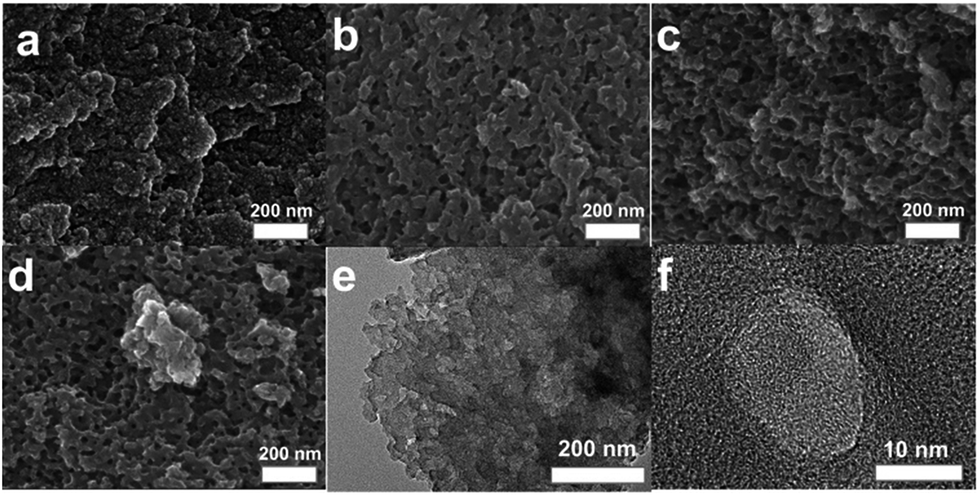
The microscopic morphology and packing texture of the NSHPC materials and their parent resins were further observed by scanning electron microscopy (SEM) and transmission electron microscopy (TEM) techniques (Fig. 2). As shown in Fig. 2a, it is obvious that the parent phenolic resins are composed of a large amount of small-sized polymer nanoparticles. Due to the high surface energy, these nanoparticles in the gels significantly aggregate together. As shown in Fig. 2b–d, the NSHPC samples exhibit a porous architecture and the pore size is about tens of nanometres. This porous texture seems to be formed by the packing of many carbon particles. Clearly, the size of the carbon particles (about 50–150 nm as-observed from the SEM images) is much larger than that of their parent gels. This fact indicates that the adjacent gel particles maybe sinter after the high temperature carbonization treatments. High resolution TEM images (Fig. 2e and f) clearly present highly interconnected and worm-like microporosity with short pore length. The micropores are a result of the homogeneous “in situ activation” of K+ ions mono-dispersed as a form of –OK group. Thus, the SEM and TEM observations, along with N2 sorption data, revealed a hierarchical pore texture for the NSHPC samples.
 |
| | Fig. 2 The SEM images of (a) the parent resin gel, (b) NSHPC-700, (c) NSHPC-800, and (d) NSHPC-900. (e and f) The TEM images of NSHPC-700. | |
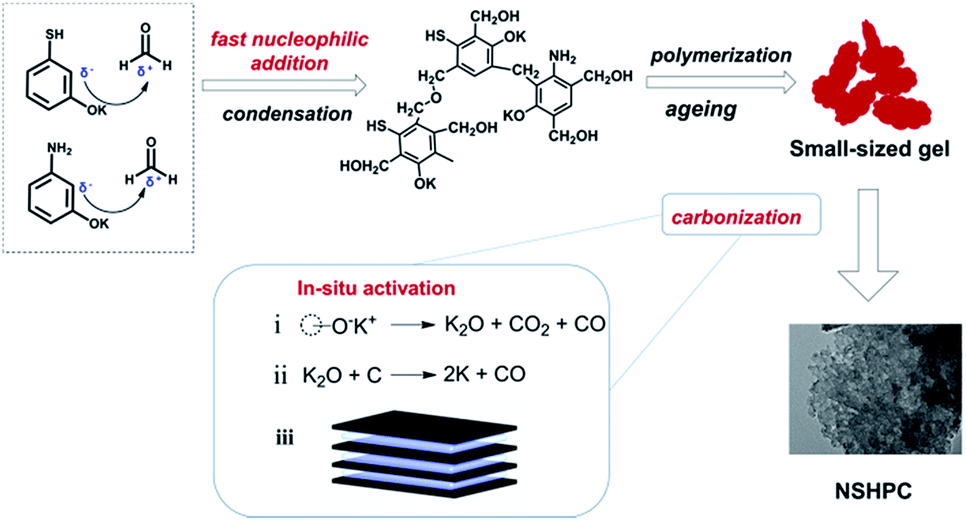
Fig. 3 illustrates the formation of hierarchical porosity. In a typical synthesis, 3-aminophenol, 3-mercaptophenol, KOH and formaldehyde were dissolved into EtOH/H2O to form a pale yellow solution. Potassium phenoxides were produced by a neutral reaction between KOH and the phenolic hydroxyl groups. After a continuous process, including nucleophilic condensation, polymerization and ageing reaction, potassium salts of the phenolic resin, were obtained in the form of dark red hydrogels. The nucleophilic addition reaction between 3-aminophenols, 3-mercaptophenol and formaldehyde leads to the formation of hydroxymethyl derivatives that subsequently undergo an intermolecular condensation reaction to yield methylene and methylene ether bridges. The addition reaction is very fast under the basic conditions used herein (pH ∼ 10), this results in a large number of primary polymer particles and thus form small-sized gel particles after the polymerization and ageing process.35,36 Furthermore, the adjacent gel particles sintered into larger-sized carbon particles during the high temperature carbonization process, thus forming the mesoporosity. In the case of microporosity, it is clearly that K+ plays a critical role. The K+ ions are mono-dispersed in the bulk of resins as a group of –OK. The pore creating process in this study can be roughly divided into three steps. First, the –OK groups decompose into K2O, CO, and CO2. Second, the carbon frameworks were etched by the redox reactions and proceeds as K2O + C → 2K + CO.37 Gibbs free energies (ΔG), calculated by the Van't Hoff equation, are −8.35, −26.05, −54.52 and −83 kJ mol−1 at 600, 700, 800 and 900 °C, respectively. It revealed the reduction process to be thermodynamically feasible. Third, the metallic K intercalates into the carbon lattices of the carbon matrix responsible for both stabilization and widening of the spaces between the carbon atomic layers, thus developing ultra-microporosity.38 Due to its mono-dispersion, the K+ ions deliver a homogeneous “in situ activation”, thus creating the developed microporosity with high uniformity, connectivity and short pore length.
 |
| | Fig. 3 Illustration of formation of hierarchical porosity. | |
The surface elemental compositions of the as-prepared carbons were determined by EDS and XPS measurements (Fig. 4 and 5). As shown in Fig. 4, heteroatoms, including N, O and S atoms, were observed. These heteroatoms were homogeneously distributed on the carbon surface as confirmed by EDS mapping (Fig. 4a). The elemental compositions determined by XPS are shown in Table S1.† Apparently, the heteroatom (N, O, and S) content of the prepared carbons roughly decreased as the carbonization temperature was increased. High resolution XPS was further used to investigate the atom binding states of the prepared carbons (Fig. 5 and S1†). In the case of C-species, the peaks at 284.7, 285.4 and 286.4 eV were assigned to the groups of C![[double bond, length as m-dash]](https://www.rsc.org/images/entities/char_e001.gif) C, C–N/C–O/C–S and CO/CN, respectively (Fig. S1a–c†). In the case of the N-species, pyridinic (N-6) and pyrrolic (N-5) groups were found due to the peaks at about 398.2 and 400.4 eV, respectively (Fig. 5a–c).39 In the case of the S-species, thiophenic groups (C–S–C) and oxidized sulfur groups were determined by the peaks at about 164.7 and 168.5 eV.40,41 In the case of the O-species, three types of O-containing groups can be verified on the surface of the prepared carbons, including CO, O–C–O, and OC–O, corresponding to the peaks at 531.2, 532.3 and 533.5 eV, respectively (Fig. S1d–f†).42
C, C–N/C–O/C–S and CO/CN, respectively (Fig. S1a–c†). In the case of the N-species, pyridinic (N-6) and pyrrolic (N-5) groups were found due to the peaks at about 398.2 and 400.4 eV, respectively (Fig. 5a–c).39 In the case of the S-species, thiophenic groups (C–S–C) and oxidized sulfur groups were determined by the peaks at about 164.7 and 168.5 eV.40,41 In the case of the O-species, three types of O-containing groups can be verified on the surface of the prepared carbons, including CO, O–C–O, and OC–O, corresponding to the peaks at 531.2, 532.3 and 533.5 eV, respectively (Fig. S1d–f†).42
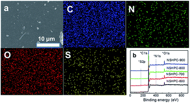 |
| | Fig. 4 (a) EDS mapping of SNC-3:1 and (b) the XPS spectra of SNC. | |
 |
| | Fig. 5 High resolution XPS spectra of: N1s (a) NSHPC-600, (b) NSHPC-700, (c) NSHPC-800, and (d) NSHPC-900; S2p (e) NSHPC-600, (f) NSHPC-700, (g) NSHPC-800 and (h) NSHPC-900. | |
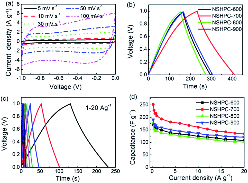
The prepared carbon materials were employed as electrode materials in supercapacitors. Fig. 6 shows the capacitive performance in a KOH electrolyte. Rough rectangular-shaped CV curves are displayed by the investigated carbons, indicating the main nature of EDL capacitance for the prepared carbons. In addition, current enlargement over a wide potential range of −0.6–0 V was observed, indicating the existence of pseudo-capacitance in addition to the EDL capacitance. The pseudo-capacitance derived from the redox reactions of the N,O,S-containing groups. The proposed redox mechanisms of N,O,S-containing groups in the KOH electrolyte could be expressed by eqn (1)–(5).30,43,44
| |
 | (1) |
| |
 | (2) |
| | |
–CxO + e− + K+ ⇌ –CxO–K
| (3) |
| | |
–SO2− + 2e− + H2O ⇌ –SO− + 2OH−
| (4) |
| | |
–SO− + e− + H2O ⇌ –S(OH)− + OH+
| (5) |
where –C
xOK represents phenol-/hydroquinone-type groups and –SO
2 and –SO
− are the oxidized sulfur groups. Due to the overlap of these complex pseudo-capacitive redox reactions, non-typical redox peaks but distortions from the linear shape on the CV curves were observed (
Fig. 6a). The increase in distortion from the linear shape could be assigned to the contribution of pseudo-capacitance. It can be observed that the pseudo-capacitance only contributes a small part to the total capacitance.
 |
| | Fig. 6 Capacitive performance in KOH electrolyte: (a) CV curves for NSHPC-700 in a two-electrode system, (b) galvanostatic charge/discharge curves at 0.6 A g−1, (c) galvanostatic charge/discharge curves for NSHPC-700, and (d) the specific capacitance at different current densities. | |
At a high scan rate of 100 mV s−1, the NSHPC-700 still maintains the appearance of roughly rectangular-like shapes, indicating that this carbon has good power capability. Galvanostatic charge/discharge experiments were further carried out over a large range of current density from 0.2 to 20 A g−1. Isosceles triangle-like charge/discharge curves can be observed in Fig. 6b. The specific capacitance was calculated using the following equation:18
| |
 | (6) |
where
Cm (F g
−1) is the gravimetric specific capacitance of the carbon samples,
I (A) is the discharge current,
t (s) is the discharge time, Δ
V (V) is the potential window of the cell, and
m (g) is the total mass of active materials in the cell. At 0.2 A g
−1, the value of
Cm are determined to 170, 252, 177 and 191 F g
−1 for NSHPC-600, NSHPC-700, NSHPC-800 and NSHPC-900, respectively. At 20 A g
−1, NSHPC-700 still obtains a high specific capacitance of 134 F g
−1. The retention ratios of the prepared carbons were calculated to be 62.8%, 53.2%, 57.5% and 63.3% in the range of 0.2–20 A g
−1. The good capacitance retention performance reflects that the ions of electrolyte could transfer rapidly and smoothly in the pores of this carbon, which is partially due to the tailored hierarchical porosity with well-connectivity and short length of ultra-micropores. Surprisingly, NSHPC-900 shows better capacitive performance than NSHPC-800, although these two carbons possess almost the same porosity. The possible reasons for this may be: (a) the lower micropore size for NSHPC-900 than NSHPC-800 due to the larger shrinkage of the carbon framework at high carbonization temperature resulting in a lower
d value
7 and (b) the higher conductivity of NSHPC-900 due to the higher carbonization degree.
Nyquist plots of the prepared carbons in a frequency range from 10 mHz to 100 kHz were measured. As shown in Fig. 7a, arranging the frequency from low to high order, the obtained Nyquist plots are divided into four distinct parts. Those are a horizontal axis-intercept, an uncompleted semicircle part, a short incline (about 45°) and a nearly vertical line. The Nyquist plots were further simulated by ZView software (Fig. 7b). The real impedance corresponding to the horizontal axis-intercept is the sum of ohmic resistances (Rs) derived from the electrolyte and the contact between the electrode and the current collector. The uncompleted semicircle loop observed in the range of medium–high frequencies stand for charge transfer resistance (Rct) at the interface between the electrolyte and electrode, which is generally proportional to the pseudo-capacitance. Clearly, Rs decreased from NSHPC-600 to NSHPC-900 (Table 2). Upon increasing the carbonization temperature, the carbonization degree increases, thus resulting in a large increase in the conductivity (i.e. a sharp decrease in Rs).14 The situation for Rct is complicated (Table 2). The carbonization temperature should respond to this result because this factor is the only difference in the preparation of the NSHPC samples. Most of electrochemical active N,S,O-containing groups are removed at higher temperature, resulting in a lower contribution from the pseudo-capacitance, thus exhibiting a lower Rct. At the same time, the removal of polar heteroatom species will decrease the wettability between the carbon surface and aqueous electrolyte resulting in an increase in the charge transfer resistance. Furthermore, the high heteroatom-doping, especially S-doping, can introduce more defect sites in the carbon materials along with the decrease of graphitization degree, which are also bad for charge transfer between the electrolyte and electrode, leading to the higher Rct value for NSHPC-700. Those are also why the NSHPC-700 material obtained the lowest capacitance retention ratio at higher discharge current densities. The 45° slope regions in the middle frequencies was ascribed to the Warburg impedance (W) in response to the frequency dependence of ion diffusion/transport from electrolyte to the micropore surface of carbon electrode. The short lengths of these slopes for NSHPC-800 and NSHPC-900 indicate that the electrolyte ions diffuse rapidly in this carbon framework (Fig. 7a inset). The nearly vertical line at low frequencies represents the main nature of the EDL capacitive behaviors.
 |
| | Fig. 7 Electrochemical impedance spectra of the NSHPC samples (a) Nyquist plots, (b) Nyquist plot simulation of NSHPC-700, (c) normalized real capacitance and (d) Bode plots. | |
Table 2 The specific capacitance at 0.2 A g−1, retention ratio at 20 A g−1, retention ratio at 1 Hz and resistance of the activated carbons
| Samples |
Cm (F g−1) |
Retention at 20 A g−1 |
Retention at 1 Hz |
Rs (Ω) |
Rct (Ω) |
τ0 (s) |
| NSHPC-600 |
170 |
62.8% |
28% |
0.15 |
0.50 |
0.34 |
| NSHPC-700 |
252 |
53.2% |
15% |
0.15 |
0.92 |
0.76 |
| NSHPC-800 |
177 |
57.5% |
27% |
0.06 |
0.54 |
0.34 |
| NSHPC-900 |
191 |
63.3% |
50% |
0.04 |
0.22 |
0.16 |
The Nyquist plots are further analysed using the following equations:45
| |
 | (7) |
| |
 | (8) |
| |
 | (9) |
where
Z(
ω) is the complex impedance,
Z′(
ω) is the real impedance,
Z′′(
ω) is the imaginary impedance,
C′(
ω) is the real capacitance,
C′′(
ω) is the imaginary capacitance,
f0 is a frequency corresponding to peak value of
C′′(
ω), and
τ0 is the time relaxation constant. The plots of normalized
C′(
ω) and
C′′(
ω) dependence on frequency are illustrated in
Fig. 7c and d, respectively. The real capacitance values remain almost constant when the frequencies are smaller than 0.1 Hz and obviously decrease over 0.1 Hz. At low frequencies, the electrolyte ions have enough time to diffuse deep inside the pores of the NSHPC samples, resulting in high capacitance. Upon increasing the frequency, the electrolyte ions have access to less and less pore surface, leading to a sharp decrease in the capacitance. It should be noted that the NSHPC-900 carbon still have 50% of the saturated capacitance at a frequency of 1.0 Hz. The plots of normalized
C′′(
ω) dependence on frequency obtain the time constant of the cells, which signifies the minimum time needed to discharge all the energy from the device with an efficiency of >50%. According to
eqn (9), the time constant were determined to be 0.34, 0.76, 0.34 and 0.16 s for NSHPC-600, NSHPC-700, NSHPC-800 and NSHPC-900, respectively. The good retention ratio of real capacitance and the very low relaxation time constant of NSHPC-900 suggest that this carbon is promising for alternating current applications and high power applications. This good performance benefits from the hierarchical porosity and high conductivity, which is conducive to the diffusion of electrolyte ions and electrode transfer, respectively.
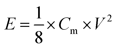
The energy density (E) and powder density (P) can be calculated from the galvanostatic charge/discharge test using the following equations:18
| |
 | (10) |
| |
 | (11) |
where
Cm,
V and
t are the gravimetric specific capacitance of the carbon materials, discharge voltage decrease and discharge time, respectively. It can be observed that all the Ragone plots gradually slope down as the power density increases, which means that less energy can be released at a higher power output. A remarkable energy density of 8.75 W h kg
−1 was delivered by NHPC-700. The long-term cyclic stability of NHPC-700 was measured using galvanostatic charge/discharge tests up to 5000 cycles at 4 A g
−1 (
Fig. 8b). Prior to the fabrication of a button supercapacitor, the KOH electrolyte was continuously bubbled with N
2 for at least 0.5 h to remove the dissolved O
2. The capacitance of NSHPC-700 gradually decreases during the cyclic test, which may be due to a partial loss of pseudo-capacitance as a result of the decomposition of some unstable electro-active groups (
e.g. carbonate acid or oxidized sulfur groups) during long time charge/discharge cycles. This carbon shows an excellent characteristic of recycling charge/discharge performance with relatively high capacitance value of 190 F g
−1 after 5000 cycles and about 97% of the discharge capacitance in the initial cycle.
 |
| | Fig. 8 (a) Ragone plots of the NSHPC samples, (b) specific capacitance and its retention ratio (inset) of NSHPC-700. | |
Conclusions
By simply carbonizing potassium salts of 3-amionphenol-3-mercaptophenol co-resin, we prepared hierarchical N,S-doped porous carbons. The key to fabricate the hierarchical porosity is the pre-introduction of potassium ions. The fast nucleophilic addition between the phenols and formaldehyde produced nano-sized gel particles, followed by carbonization into carbon particles, finally resulting in mesoporosity. The activating effect of the potassium ions delivered abundant ultra-microporosity. Due to the synergistic effects of the tailored porosity and N,S,O-doping, the prepared carbons show a high specific capacitance (252 F g−1 for NSHPC-700), good capacitance retention in the range of 0.2–20 A g−1 and very low relaxation time constant of 0.16 s in a KOH electrolyte.
Acknowledgements
We are grateful for the financial support given by the Natural Science Foundation of China (NSFC51302156, 21576158, 21576159 and 21476132).
Notes and references
- P. Simon, Y. Gogotsi and B. Dunn, Science, 2014, 343, 1210–1211 CrossRef CAS PubMed.
- F. Beguin, V. Presser, A. Balducci and E. Frackowiak, Adv. Mater., 2014, 26, 2219–2251 CrossRef CAS PubMed.
- A. Ghosh and Y. H. Lee, ChemSusChem, 2012, 5, 480–499 CrossRef CAS PubMed.
- S. L. Candelaria, Y. Shao, W. Zhou, X. Li, J. Xiao, J.-G. Zhang, Y. Wang, J. Liu, J. Li and G. Cao, Nano Energy, 2012, 1, 195–220 CrossRef CAS.
- Q. Wang, J. Yan, Y. Wang, T. Wei, M. Zhang, X. Jing and Z. Fan, Carbon, 2014, 67, 119–127 CrossRef CAS.
- L.-F. Chen, X.-D. Zhang, H.-W. Liang, M. Kong, Q.-F. Guan, P. Chen, Z.-Y. Wu and S.-H. Yu, ACS Nano, 2012, 6, 7092–7102 CrossRef CAS PubMed.
- L. Borchardt, M. Oschatz and S. Kaskel, Mater. Horiz., 2014, 1, 157–168 RSC.
- C. Largeot, C. Portet, J. Chmiola, P.-L. Taberna, Y. Gogotsi and P. Simon, J. Am. Chem. Soc., 2008, 130, 2730–2731 CrossRef CAS PubMed.
- J. Chmiola, G. Yushin, Y. Gogotsi, C. Portet, P. Simon and P. L. Taberna, Science, 2006, 313, 1760–1763 CrossRef CAS PubMed.
- B. Xu, S. Hou, H. Duan, G. Cao, M. Chu and Y. Yang, J. Power Sources, 2013, 228, 193–197 CrossRef CAS.
- Y. Zhao, M. Liu, L. Gan, X. Ma, D. Zhu, Z. Xu and L. Chen, Energy Fuels, 2014, 28, 1561–1568 CrossRef CAS.
- Y. Zhao, M. Liu, X. Deng, L. Miao, P. K. Tripathi, X. Ma, D. Zhu, Z. Xu, Z. Hao and L. Gan, Electrochim. Acta, 2015, 153, 448–455 CrossRef CAS.
- T. Thomberg, T. Tooming, T. Romann, R. Palm, A. Jänes and E. Lust, J. Electrochem. Soc., 2013, 160, A1834–A1841 CrossRef CAS.
- E. Raymundo-Piñero, K. Kierzek, J. Machnikowski and F. Béguin, Carbon, 2006, 44, 2498–2507 CrossRef.
- D.-W. Wang, F. Li, M. Liu, G. Lu and H.-M. Cheng, Angew. Chem., Int. Ed., 2008, 47, 373–376 CrossRef CAS PubMed.
- C. H. Huang, Q. Zhang, T. C. Chou, C. M. Chen, D. S. Su and R. A. Doong, ChemSusChem, 2012, 5, 563–571 CrossRef CAS PubMed.
- W. Huang, H. Zhang, Y. Huang, W. Wang and S. Wei, Carbon, 2011, 49, 838–843 CrossRef CAS.
- W. Xing, C. C. Huang, S. P. Zhuo, X. Yuan, G. Q. Wang, D. Hulicova-Jurcakova, Z. F. Yan and G. Q. Lu, Carbon, 2009, 47, 1715–1722 CrossRef CAS.
- K. Xia, Q. Gao, J. Jiang and J. Hu, Carbon, 2008, 46, 1718–1726 CrossRef CAS.
- Z. Zheng and Q. Gao, J. Power Sources, 2011, 196, 1615–1619 CrossRef CAS.
- F. Ruo-wen, L. Zheng-hui, L. Ye-ru, L. Feng, X. Fei and W. Ding-cai, New Res. Carbon Mater., 2011, 26, 171–179 CrossRef.
- X. Wang, K. N. Bozhilov and P. Feng, Chem. Mater., 2006, 18, 6373–6381 CrossRef CAS.
- J. Wang, M. Oschatz, T. Biemelt, L. Borchardt, I. Senkovska, M. R. Lohe and S. Kaskel, J. Mater. Chem., 2012, 22, 23893–23899 RSC.
- Y. Lv, F. Zhang, Y. Dou, Y. Zhai, J. Wang, H. Liu, Y. Xia, B. Tu and D. Zhao, J. Mater. Chem., 2012, 22, 93 RSC.
- T.-Z. Ren, L. Liu, Y. Zhang and Z.-Y. Yuan, J. Solid State Electrochem., 2013, 17, 2223–2233 CrossRef CAS.
- T.-Z. Ren, L. Liu, Y. Zhang and Z.-Y. Yuan, J. Solid State Electrochem., 2013, 17, 927–935 CrossRef CAS.
- L. Zhao, L. Z. Fan, M. Q. Zhou, H. Guan, S. Qiao, M. Antonietti and M. M. Titirici, Adv. Mater., 2010, 22, 5202–5206 CrossRef CAS PubMed.
- D. W. Wang, F. Li, L. C. Yin, X. Lu, Z. G. Chen, I. R. Gentle, G. Q. M. Lu and H. M. Cheng, Chem.–Eur. J., 2012, 18, 5345–5351 CrossRef CAS PubMed.
- W. Si, J. Zhou, S. Zhang, S. Li, W. Xing and S. Zhuo, Electrochim. Acta, 2013, 107, 397–405 CrossRef CAS.
- X. Zhao, Q. Zhang, C.-M. Chen, B. Zhang, S. Reiche, A. Wang, T. Zhang, R. Schlögl and D. S. Su, Nano Energy, 2012, 1, 624–630 CrossRef CAS.
- B. You, L. Wang, L. Yao and J. Yang, Chem. Commun., 2013, 49, 5016–5018 RSC.
- D. W. Wang, F. Li, L. C. Yin, X. Lu, Z. G. Chen, I. R. Gentle, G. Q. M. Lu and H. M. Cheng, Chem.–Eur. J., 2012, 18, 5345–5351 CrossRef CAS PubMed.
- J. Wei, D. Zhou, Z. Sun, Y. Deng, Y. Xia and D. Zhao, Adv. Funct. Mater., 2013, 23, 2322–2328 CrossRef CAS.
- H. M. Jeong, J. W. Lee, W. H. Shin, Y. J. Choi, H. J. Shin, J. K. Kang and J. W. Choi, Nano Lett., 2011, 11, 2472–2477 CrossRef CAS PubMed.
- L. Zubizarreta, A. Arenillas, A. Domínguez, J. Menéndez and J. Pis, J. Non-Cryst. Solids, 2008, 354, 817–825 CrossRef CAS.
- G. Zhou, H. Tian, H. Sun, S. Wang and C. E. Buckley, Chem. Eng. J., 2011, 171, 1399–1405 CrossRef CAS.
- J. Dıaz-Terán, D. Nevskaia, J. Fierro, A. Lopez-Peinado and A. Jerez, Microporous Mesoporous Mater., 2003, 60, 173–181 CrossRef.
- J. Romanos, M. Beckner, T. Rash, L. Firlej, B. Kuchta, P. Yu, G. Suppes, C. Wexler and P. Pfeifer, Nanotechnology, 2012, 23, 015401 CrossRef CAS PubMed.
- J. W. F. To, J. He, J. Mei, R. Haghpanah, Z. Chen, T. Kurosawa, S. Chen, W.-G. Bae, L. Pan, J. B. H. Tok, J. Wilcox and Z. Bao, J. Am. Chem. Soc., 2016, 138, 1001–1009 CrossRef CAS PubMed.
- S. Chandra, P. Patra, S. H. Pathan, S. Roy, S. Mitra, A. Layek, R. Bhar, P. Pramanik and A. Goswami, J. Mater. Chem. B, 2013, 1, 2375–2382 RSC.
- X. Zhao, Q. Zhang, C. Chen, B. Zhang, S. Reiche, A. Wang, T. Zhang, R. Schlogl and D. Su, Aromatic sulfide, sulfoxide, and sulfone mediated mesoporous carbon monolith for use in supercapacitor, 2012 Search PubMed.
- J. Figueiredo, M. Pereira, M. Freitas and J. Orfao, Carbon, 1999, 37, 1379–1389 CrossRef CAS.
- H. Liu, H. Song, X. Chen, S. Zhang, J. Zhou and Z. Ma, J. Power Sources, 2015, 285, 303–309 CrossRef CAS.
- G. Sun, D. Long, X. Liu, W. Qiao, L. Zhan, X. Liang and L. Ling, J. Electroanal. Chem., 2011, 659, 161–167 CrossRef CAS.
- P. L. Taberna, P. Simon and J. F. Fauvarque, J. Electrochem. Soc., 2003, 150, A292 CrossRef CAS.
Footnote |
| † Electronic supplementary information (ESI) available: High resolution XPS patterns of C1s and O1s. See DOI: 10.1039/c6ra08903h |
|
| This journal is © The Royal Society of Chemistry 2016 |
Click here to see how this site uses Cookies. View our privacy policy here.