An in situ confinement strategy to porous poly(3,4-ethylenedioxythiophene)/sulfur composites for lithium–sulfur batteries

Bing Ding, Zhi Chang, Jie Wang, Hui Dou* and Xiaogang Zhang
Jiangsu Key Laboratory of Materials and Technology for Energy Conversion, College of Material Science and Engineering, Nanjing University of Aeronautics and Astronautics, Nanjing, 210016, P. R. China. E-mail: azhangxg@nuaa.edu.cn

Received 29th March 2016 , Accepted 28th April 2016

First published on 29th April 2016


Abstract

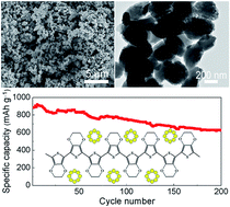
Lithium–sulfur (Li–S) batteries are receiving intense interest because of their high theoretical energy density and low cost. However, the rapid capacity fading is a significant problem facing the application of Li–S batteries. Herein, we describe an in situ confinement strategy for preparing a porous poly(3,4-ethylenedioxythiophene)/sulfur (pPEDOT/S) composite for Li–S batteries. The as-prepared pPEDOT/S composite exhibits a monodispersed nanostructure with sizes in the range of 400–600 nm. The pPEDOT/S composite electrode exhibits excellent cycling stability and high specific capacity. At a current rate of 0.5C, the pPEDOT/S electrode exhibits a high specific capacity of 883 mA h g−1 and a capacity retention of 71% after 200 cycles. During the charge/discharge process, the porous nanostructure could facilitate rapid electrolyte diffusion and accommodate the volumetric expansion. The chemical interaction between the PEDOT and polysulfides and discharged products could efficiently avoid the dissolution of polysulfides and the irreversible deposition of discharged products. The unique nanostructure plus the excellent electrochemical performances of the composites described in the current study allow for new opportunities to design high-performance electrodes for Li–S batteries.

Introduction

The development of the electric vehicle and storage of renewable energy pose significant challenges to rechargeable battery technologies. Therefore, alternative rechargeable batteries, with energy density beyond presently available lithium ion batteries (LIBs), have been extensively pursued.1 Lithium–sulfur (Li–S) batteries have risen to be a prospective candidate, as they possess a significantly higher theoretical energy density.1,2 A typical Li–S battery uses a sulfur cathode and a metal lithium anode. Assuming sulfur is completely converted to Li2S, it is expected to deliver a theoretical specific capacity of 1675 mA h g−1 and an energy density of 2600 W h kg−1, which are much higher than those of LIBs.3,4 Moreover, sulfur has the additional advantages of being low price, environmentally friendly and widely available around the globe. Despite these promising advantages, there exist multiple fundamental challenges that prevent the widespread practical realization of Li–S batteries. The major obstacle is the rapid capacity fading of the sulfur cathode, which is caused by several reasons: (i) the insulating nature of sulfur and the discharged products (Li2S2/Li2S); (ii) large volumetric expansion of sulfur during the discharge process; and (iii) high dissolution and shuttling of intermediate lithium polysulfides during the charge/discharge process.5–7

To solve these problems, much effort has been devoted to designing novel nanostructured sulfur electrodes by encapsulating elemental sulfur into a porous and conductive framework such as mesoporous carbon,8–10 microporous carbon,11,12 hierarchically porous carbon13–16 and graphene.17,18 These porous carbon materials effectively enhance the conductivity of the electrode and could trap polysulfides to some extent. However, recent research showed that porous carbon may not be an ideal matrix for confining sulfur. First, over long-term charge/discharge cycling, the hydrophilic lithium polysulfides will diffuse from the hydrophobic pores of porous carbon materials.19–22 Moreover, the low binding energy between the nonpolar carbon and polar Li2S2/Li2S will cause detachment of Li2S2/Li2S from the carbon surface, resulting in loss of electrical contact and decay of capacity.23 Conductive polymers have been explored as promising candidates for sulfur encapsulation due to their high electrical conductivity and easily-controllable morphology.23–26 Notable examples include the study of Liu et al., who reported a three-dimensional, cross-linked sulfur-polyaniline polymer as a backbone for encapsulating sulfur.25 This polymer framework provides strong physical and chemical confinement to sulfur and the resident polysulfide. However, in previous reports, the polymer backbones needed to be pre-prepared and then encapsulated with elemental sulfur into the frameworks through melt-diffusion. This type of approach increases the problem that ex situ confinement of sulfur is highly limited by the host structure and surface chemistry. In addition, these conductive polymers suffer from much lower specific surface areas and electrical conductivity than porous carbon materials. As a result, in many cases, sulfur precipitation on the outer surface of the host matrix could not be avoided.24,27 To realize better confinement, a bottom-up synthesis method was also employed to fabricate a core–shell or yolk–shell nanostructured sulfur electrode.28–31 For example, a core–shell sulfur/polythiophene composite was synthesized through in situ chemical oxidative polymerization of polythiophene on the surface of sulfur nanoparticles.30 Cui et al. reported monodispersed polyvinylpyrrolidone-encapsulated hollow sulfur nanospheres composite.31 Modification of the sulfur nanosphere surface with conductive poly(3,4-ethylenedioxythiophene) (PEDOT) allows the electrode to achieve excellent high-rate capability and cycling performance. These shell coatings could restrict the dissolution of sulfur in the electrolyte and improve the cycling performances of the sulfur electrode. However, these nanostructures with conducting polymer coating shells were all achieved through a multi-step chemical oxidative polymerization. Moreover, sulfur nanoparticles or nanostructures need to be pre-prepared. Therefore, developing a facile and in situ confinement strategy to a porous sulfur electrode remains a challenge.

Herein, we are motivated to develop an in situ confinement strategy to prepare a porous PEDOT/S (pPEDOT/S) composite for Li–S batteries. In the confined and ordered mesopores, the autocatalytic polymerization of dibromized 3,4-ethylenedioxythiophene (DBDEOT) forms a continuous conductive framework. As the conductive framework forms in the liquid sulfur, the sulfur could contact with the conductive framework at molecule level. The as-prepared pPEDOT/S composite exhibits excellent cycling stability with high specific capacity.

2. Experimental section

2.1 Preparation of mp PEDOT/S composite

First, DBEDOT and SBA-15 template were synthesized through the method described in a previous report (see ESI). Porous PEDOT/S composite was prepared through nano-casting followed by in situ self-polymerization. Typically, 60 mg elemental sulfur and 80 mg DBEDOT were dissolved in 50 mL chloroform. Then, 100 mg SBA-15 template was added in the solution and the mixture was stirred for 12 h to ensure the complete loading of DBEDOT and elemental sulfur in the SBA-15. The solvent was evaporated under 100 Pa at room temperature. The dry powder was ground and maintained at 160 °C for 5 h. Finally, the SBA-15 template was removed by stirring with 5% HF and then porous PEDOT/S (pPEDOT/S) was obtained after washing with de-ionized water and drying at 50 °C. For comparison, PEDOT/S composite were also prepared without the SBA-15 template. Typically, 60 mg DBEDOT and 40 mg elemental sulfur were well mixed and then heated at 160 °C for 5 h. The composite was also washed with de-ionized water to remove the residual bromine. PEDOT was prepared by the heating of DBEDOT at 160 °C for 5 h and washing with de-ionized water.

2.2 Structural characterization

Fourier transform infrared (FT-IR) spectra were obtained with a model 360 Nicolet AVATARFT-IR spectrophotometer. X-ray diffraction (XRD) patterns were obtained on a Bruker-AXS D8 DISCOVER. Cu Kα line was used as a radiation source with λ = 0.15406 nm. Scanning electron microscopy (SEM) and energy dispersive spectroscopy (EDS) were carried out with HitachiS-4800. Transmission electron microscopy (TEM) was carried out with FEI TECNAI-20. Thermal gravimetric analysis (TGA) was conducted on a NETZSCH STA 409 PC under nitrogen protection at a heating rate of 10 °C min−1 from 30 to 500 °C.STEM. Electrical conductivity measurements were carried out at room temperature using the four-point method.

2.3 Electrochemical test

Electrochemical characterization was carried out by galvanostatic cycling in a CR2016-type coin cell. The working electrodes were prepared by a slurry coating procedure. The slurry consisted of 70 wt% active material, 20 wt% acetylene black and 10 wt% polyvinylidene fluoride (PVDF) dissolved in N-methyl pyrrolidinone (NMP), and was uniformly spread on an aluminium foil current collector. Finally, the electrode was transferred to oven and dried at 60 °C overnight. The active material loading on each electrode was about 1 mg cm−2. Test cells were assembled in an argon-filled glove box using Li foil as the counter electrode and polypropylene film as the separator. The electrolyte was 1 M lithium bis(trifluoromethanesulfone)imide (LiTFSI) and 0.1 M LiNO3 in a mixed solvent of 1,3-dioxolane (DOL) and 1,2-dimethoxyethane (DME) with a volume ratio of 1[thin space (1/6-em)]:[thin space (1/6-em)]1. The coin cells were galvanostatically charged/discharged between 1.5 and 3.0 V (vs. Li/Li+) using a CT2001A cell test instrument (LAND Electronic Co.). The cyclic voltammetry (CV) and electrochemical impedance spectroscopy (EIS) measurement was conducted with a Zive SP2 electrochemical workstation (WonATech Co. Ltd, Korea).

3. Results and discussion

The porous PEDOT/S composite was prepared through in situ autocatalytic polymerization in the confined meso-space of the SBA-15 template. As illustrated in Fig. 1a, first, elemental sulfur and DBEDOT monomer were encapsulated into the ordered mesoporous channel of SBA-15 through the nano-casting method. Then, the PEDOT conductive framework could in situ form via the autocatalytic polymerization of DBEDOT at 180 °C (Fig. 1b), wherein elemental sulfur melted. The liquid sulfur is imbedded into the framework, whereupon it solidifies and maintains intimate contact with the PEDOT framework. After removing the SBA-15 template, pPEDOT/S composite was obtained. Compared with chemical oxidative polymerization, the PEDOT framework was in situ formed in the presence of liquid sulfur. Therefore, elemental sulfur could make close contact with the conductive framework at the molecule-level (Fig. 1c).
image file: c6ra08104e-f1.tif
Fig. 1 Illustration of (a) fabrication route of pPEDOT/S composite, (b) self-polymerization of DBEDOT through autocatalytic polymerization and (c) structure of pPEDOT/S composite.

To realize better encapsulation of PEDOT and elemental sulfur, SBA-15 with short pore length was prepared as the template. As shown in the SEM image, the as-prepared SBA-15 shows a nanostructure of monodispersed nanoparticles with sizes of about 400–600 nm (Fig. S1a). The reflections in the small angle XRD pattern (Fig. S1b) of SBA-15 could be assigned to (100), (110), and (200) reflections of the 2-D hexagonal p6mm space group, indicating an ordered nanostructure.32 The as-prepared pPEDOT/S replica shows similar morphology and size as the SBA-15 template (Fig. 2). As shown in the SEM images, we observe that the pPEDOT/S composite exhibits a monodispersed nanostructure and the surface becomes much rougher (Fig. 2a and b). Moreover, large particles or aggregations are not found in the composite, which indicates that the conducting polymer and elemental sulfur are completely encapsulated in the pores during the autocatalytic polymerization process. Energy dispersive spectroscopic (EDS) mapping of elemental C, O and S show uniform dispersion, which suggests uniform dispersion of PEDOT and elemental sulfur in the pPEDOT/S composite. Fig. 2c and d describe the TEM images of the pPEDOT/S composite. In the TEM images, we did not observe an ordered mesoporous channel. However, disordered pores were obvious in the nanoparticles. This is probably due to the soft backbone of the polymer collapsing during self-polymerization or the template etching process.


image file: c6ra08104e-f2.tif
Fig. 2 (a and b) SEM images and (c and d) TEM images of pPEDOT/S composite.

We also investigated the effect of the SBA-15 template on the morphology of the composite. As shown in Fig. S3a and b, the PEDOT/S composite prepared without SBA-15 template exhibits an irregular morphology with a size of up to several micrometers. TEM images indicate that the PEDOT interconnect with each other and elemental sulfur was loaded in the framework. To probe the PEDOT framework in the composite, elemental sulfur was dissolved by chloroform and the morphology of residual PEDOT was investigated. As shown in Fig. S4, the residual PEDOT shows the morphology of a nanoparticle and the size is much smaller than that of the PEDOT/S composite. This suggests that the PEDOT framework in situ forms in the melt sulfur, producing intimate contact between sulfur and PEDOT.

To confirm the polymerization of DBEDOT, FT-IR spectra of the PEDOT and PEDOT/S composite were conducted. As shown in Fig. 3a, the FT-IR spectra of the PEDOT and PEDOT/S composites show characteristic peaks originating from PEDOT. The peaks at 1552 and 1473 cm−1 are assigned to the conjugated C[double bond, length as m-dash]C asymmetric and symmetric stretching vibration in the thiophene ring, respectively. The peak at 1355 cm−1 corresponds to the C–C stretching in the thiophene ring. The C–O antisymmetric stretching at 1074 cm−1 arises from the ethylenedioxy group.33 Moreover, the electric conductivity of the PEDOT is up to 1.2 S cm−1, which is even higher than ordered mesoporous carbon prepared through high-temperature carbonization of sucrose.8 The high electric conductivity of PEDOT could be contributed to the doping with Br3 during autocatalytic polymerization.33,34 All these results support the formation of the conductive PEDOT framework through simple autocatalytic polymerization of DBEDOT. To investigate the state of sulfur in the composites, PEDOT/S composites were measured by XRD patterns. Fig. 3b shows the XRD patterns of PEDOT, PEDOT/S and pPEDOT/S composites. The XRD pattern of PEDOT show a broad peak centered at 2θ = 26°, which is attributed to the periodicity parallel and perpendicular to the PEDOT chains.35 The XRD pattern of the PEDOT/S and pPEDOT/S composite exhibits characteristic diffraction peaks of sulfur, indicating a well-defined crystal structure of sulfur in the composites. However, compared with the PEDOT/S composite, the pPEDOT/S composite shows obviously weakened diffraction peaks, which reveal that elemental sulfur is incorporated in the polymer and forms particles with smaller sizes. The sulfur content in the pPEDOT/S composite was analyzed by TGA under a nitrogen atmosphere. As shown in Fig. S4, the TGA curve shows one weight loss stage at ca. 180–310 °C, reflecting the evaporation of sulfur. The corresponding weight loss is approximately 61 wt%.


image file: c6ra08104e-f3.tif
Fig. 3 (a) FT-IR spectra of PEDOT and PEDOT/S composites. (b) XRD patterns of PEDOT, PEDOT/S and pPEDOT/S composites.

Electrochemical measurements were carried out to evaluate the electrochemical performance of the pPEDOT/S composite. Fig. 4a shows the CV of the pPEDOT/S electrode at 0.2 mV s−1. The curves show typical characteristics of the electrochemical reaction of a sulfur electrode. During the cathodic scan, two discrete reduction peaks positioned around 2.3 and 2.0 V were observed, indicating a two-step reduction of elemental sulfur. The first reductive peak at ∼2.3 V corresponds to the transformation of S8 to long-chain soluble lithium polysulfides (Li2Sn, 4 ≤ n ≤ 8). The second peak at ∼2.0 V is attributed to the decomposition of the polysulfides to form insoluble short-chain lithium sulfides (Li2S2/Li2S). In the subsequent anodic scan, only one intense oxidation peak was found at ∼2.6 V because of the slow oxidation kinetics of lithium sulfide to lithium polysulfides.13,36 After the first cycle, the redox peak currents and potentials show no obvious change in the following scanning, which indicates good reactive reversibility and cycling stability of the PEDOT/S composite electrode. Fig. 4b shows the galvanostatic discharge/charge profiles of the PEDOT/S composite electrode at a current rate of 0.5C (1C = 1675 mA g−1). The pPEDOT/S electrode shows two apparent discharge plateaus and one charge plateau, which agree well with the current peaks in the CV plots (Fig. 4a). As shown in the galvanostatic discharge/charge profiles, the electrode shows relatively low initial discharge capacities and larger over potential. After the 1st charge/discharge cycle, the electrodes showed a gradual increase in discharge capacity. This behavior indicates that the PEDOT/S composite electrode requires an activation step.37 The possible reason for the activation process is that the surface area and contact surface area of the as-prepared pPEDOT/S composite is low and active sulfur is confined in the conductive polymer. Therefore, it takes some time for the electrolyte to diffuse into the internal surfaces of the active material.25,37 Fig. 4c compares the cycling performances of the PEDOT/S and pPEDOT/S electrodes. At a current rate of 0.5C, the two electrodes exhibit initial discharge capacities of 883 and 850 mA h g−1 (the specific capacity values were calculated based on the mass of sulfur loading on the electrode). The high specific capacity of the composite electrodes should be attributed to the high electrical conductivity of the PEDOT host, thus improving the electrochemical utilization of sulfur. For the pPEDOT/S electrode, the capacity increases gradually during the first ten cycles and reaches a maximum capacity of 904 mA h g−1. After cycling for 200 cycles, the capacity still remains 626 mA h g−1 and capacity retention is up to 71%. In contrast, the PEDOT/S electrode shows much poorer cycling performance. The specific capacity rapidly decreases to 379 mA h g−1 after 200 cycles. Even at a high rate of 1C, the pPEDOT/S electrode also exhibits superior cycling performance (Fig. 4d). After 200 cycles, the capacity is 475 mA h g−1 and capacity retention is 79%, which is much better than previously reported conducting polymer/sulfur electrodes.27,38–40


image file: c6ra08104e-f4.tif
Fig. 4 Electrochemical performances of pPEDOT/S composite electrode: (a) CV curves at 0.2 mV s−1 and (b) galvanostatic charge/discharge profiles of the PEDOT/S composite electrode at 0.5C. (c) Comparison of cycling performances of PEDOT/S and pPEDOT/S electrodes at 0.5C. (d) Cycling performance of pPEDOT/S electrode at 1C.

For a sulfur electrode, the inescapable aggregation of insulated discharged product (Li2S2/Li2S) on the electrode surface during cycling has a negative impact on the electrochemical performance.41–43 To obtain further insights into the electrochemical reaction process, EIS of the PEDOT/S and pPEDOT/S electrodes after cycling were measured and are collected in Fig. 5. Both of the EIS spectra are composed of a depressed semicircle in the high-frequency region and a sloping straight line in the low-frequency region, which correspond to the charge-transfer process and the Warburg diffusion process, respectively. As shown in the equivalent circuit (Fig. S6), Re is the resistance of the electrolyte, Rct/CPE2 is the charge transfer resistance and its relative capacitance, R1/CPE1 is the resistance of Li2S2/Li2S film and its relative capacitance.37,41,44 Obviously, the Rct of the pPEDOT/S electrode is much smaller than that of the PEDOT/S electrode. This indicates that the irreversible deposition and aggregation of insoluble reduction products on the surface of the pPEDOT/S electrode was not serious for the fully charged state. As discussed in previous study, the heteroatoms (O and S) in the PEDOT framework strongly bind with the lithium atom in Li2S, which may suppress the irreversible deposition of Li2S on the surface of the electrode, thus improving the cycling stability.23 As discussed above, the excellent electrochemical performances of the pPEDOT/S electrode should be ascribed to the in situ confinement, porous nanostructure and the chemical interaction between the sulfur species and the PEDOT framework. First, unlike other ex situ infusion of sulfur into a pre-prepared host (such as porous carbon, conducting polymers), PEDOT was in situ formed in the confined meso-space through autocatalytic polymerization. This in situ confinement of sulfur could promise better electric contact between elemental sulfur and the conductive framework. The in situ confinement could better prevent dissolution and shuttling of lithium polysulfide during charge/discharge cycling. Furthermore, the chemical interaction between the heteroatoms in the PEDOT framework and the polysulfides could mitigate the dissolution of lithium polysulfides. Second, the porous nanostructure could accommodate the large volumetric expansion of sulfur during the discharge process. Therefore, mechanical stress arising from the volumetric expansion is effectively alleviated.


image file: c6ra08104e-f5.tif
Fig. 5 EIS spectra of PEDOT/S and pPEDOT/S electrodes after cycling.

4. Conclusions

In conclusion, we describe an in situ confinement strategy for preparing a porous PEDOT/S composite. The as-prepared porous PEDOT/S composite exhibits high specific capacity and excellent cycling performances. After 200 cycles at 0.5C, the porous PEDOT/S electrode remains at a specific capacity of 626 mA h g−1 with a capacity retention of 71%. The molecule-level electrical contact and chemical interaction between the heteroatoms in the PEDOT framework and polysulfides could efficiently mitigate the dissolution and shuttle lithium polysulfides in the electrolyte. During the charge/discharge process, the porous nanostructure could facilitate rapid electrolyte diffusion and accommodate the volumetric expansion. The in situ confinement plus the excellent electrochemical performances provide a new opportunity to design and fabricate superior nanostructured electrodes for energy storage devices.

Acknowledgements

The study was funded by the Natural Science Foundation of Jiangsu Province (No. BK20151468), Fundamental Research Funds for the Central Universities of NUAA (NJ20160104) and Priority Academic Program Development of Jiangsu Higher Education Institutions (PAPD). B. Ding is grateful to Funding of Jiangsu Innovation Program for Graduate Education (CXZZ13_0158) and Outstanding Doctoral Dissertation in NUAA (BCXJ13-13).

Notes and references

  1. P. G. Bruce, S. A. Freunberger, L. J. Hardwick and J. M. Tarascon, Nat. Mater., 2012, 11, 19 CrossRef CAS PubMed.
  2. Y. Yang, G. Y. Zhwng and Y. Cui, Chem. Soc. Rev., 2013, 42, 3018 RSC.
  3. N.-S. Choi, Z. Chen, S. A. Freunberger, X. Ji, Y.-K. Sun, K. Amine, G. Yushin, L. F. Nazar, J. Cho and P. G. Bruce, Angew. Chem., Int. Ed., 2012, 51, 9994 CrossRef CAS PubMed.
  4. A. Manthiram, Y. Z. Fu and Y. S. Su, Acc. Chem. Res., 2013, 46, 1125 CrossRef CAS PubMed.
  5. J. Hassoun and B. Scrosati, Adv. Mater., 2010, 22, 5198 CrossRef CAS PubMed.
  6. L. M. Suo, Y. S. Hu, H. Li, M. Armand and L. Q. Chen, Nat. Commun., 2013, 4, 1481 CrossRef PubMed.
  7. J. C. Guo, Z. C. Yang, Y. C. Yu, H. D. Abruna and L. A. Archer, J. Am. Chem. Soc., 2013, 135, 763 CrossRef CAS PubMed.
  8. X. L. Ji, K. T. Lee and L. F. Nazar, Nat. Mater., 2009, 8, 500 CrossRef CAS PubMed.
  9. X. L. Li, Y. L. Cao, W. Qi, L. V. Saraf, J. Xiao, Z. M. Nie, J. Mietek, J. G. Zhang, B. Schwenzer and J. Liu, J. Mater. Chem., 2011, 21, 16603 RSC.
  10. J. X. Song, T. Xu, M. L. Gordin, P. Y. Zhu, D. P. Lv, Y.-B. Jiang, Y. S. Chen, Y. S. Duan and D. H. Wang, Adv. Funct. Mater., 2014, 24, 1243 CrossRef CAS.
  11. S. Xin, L. Gu, N. H. Zhao, Y. X. Yin, L. J. Zhou, Y. G. Guo and L. J. Wan, J. Am. Chem. Soc., 2012, 134, 18510 CrossRef CAS PubMed.
  12. H. B. Wu, S. Wei, L. Zhang, R. Xu, H. H. Hng and X. W. Lou, Chem.–Eur. J., 2013, 19, 10804 CrossRef CAS PubMed.
  13. C. F. Zhang, H. B. Wu, C. Z. Yuan, Z. P. Guo and X. W. Lou, Angew. Chem., Int. Ed., 2012, 51, 9592 CrossRef CAS PubMed.
  14. B. Ding, C. Z. Yuan, L. F. Shen, G. Y. Xu, P. Nie and X. G. Zhang, Chem.–Eur. J., 2013, 19, 1013 CrossRef CAS PubMed.
  15. J. T. Lee, Y. Zhao, S. Thieme, H. Kim, M. Oschatz, L. Borchardt, A. Magasinski, W.-I. Cho, S. Kaskel and G. Yushin, Adv. Mater., 2013, 25, 4573 CrossRef CAS PubMed.
  16. Z. Li, Y. Jiang, L. X. Yuan, Z. Q. Yi, C. Wu, Y. Liu, P. Strasser and Y. H. Huang, ACS Nano, 2014, 8, 9295 CrossRef CAS PubMed.
  17. L. Ji, M. Rao, H. Zheng, L. Zhang, Y. Li, W. Duan, J. Guo, E. J. Cairns and Y. Zhang, J. Am. Chem. Soc., 2011, 133, 18522 CrossRef CAS PubMed.
  18. G. Zhou, L.-C. Yin, D.-W. Wang, L. Li, S. Pei, I. R. Gentle, F. Li and H.-M. Cheng, ACS Nano, 2013, 7, 5367 CrossRef CAS PubMed.
  19. Q. Pang, D. Kundu, M. Cuisinier and L. F. Nazar, Nat. Commun., 2015, 5, 4759 CrossRef PubMed.
  20. H. Yao, G. Zheng, P.-C. Hsu, D. Kong, J. J. Cha, W. Li, Z. W. Seh, M. T. McDowell, K. Yan, Z. Liang, V. K. Narasimhan and Y. Cui, Nat. Commun., 2014, 5, 3943 CAS.
  21. S. Zheng, F. Yi, Z. Li, Y. Zhu, Y. Xu, C. Luo, J. Yang and C. Wang, Adv. Funct. Mater., 2014, 24, 4156 CrossRef CAS.
  22. J.-J. Chen, R.-M. Yuan, J.-M. Feng, Q. Zhang, J.-X. Huang, G. Fu, M.-S. Zheng, B. Ren and Q.-F. Dong, Chem. Mater., 2015, 27, 2048 CrossRef CAS.
  23. W. Y. Li, Q. F. Zhang, G. Y. Zheng, Z. W. Seh, H. B. Yao and Y. Cui, Nano Lett., 2013, 13, 5534 CrossRef CAS PubMed.
  24. M. M. Sun, S. C. Zhang, T. Jiang, L. Zhang and J. H. Yu, Electrochem. Commun., 2008, 10, 1819 CrossRef CAS.
  25. L. Xiao, Y. Cao, J. Xiao, B. Schwenzer, M. H. Engelhard, L. V. Saraf, Z. Nie, G. J. Exarhos and J. Liu, Adv. Mater., 2012, 24, 1176 CrossRef CAS PubMed.
  26. Y. Fu and A. Manthiram, Chem. Mater., 2012, 24, 3081 CrossRef CAS.
  27. Y. G. Zhang, Z. Bakenov, Y. Zhao, A. Konarov, N. L. D. The, M. Malik, T. Paron and P. Chen, J. Power Sources, 2012, 208, 1 CrossRef CAS.
  28. H. Chen, W. Dong, J. Ge, C. Wang, X. Wu, W. Lu and L. Chen, Sci. Rep., 2013, 3, 1910 Search PubMed.
  29. Y. Fu and A. Manthiram, J. Phys. Chem. C, 2012, 116, 8910 CAS.
  30. F. Wu, J. Z. Chen, R. J. Chen, S. X. Wu, L. Li, S. Chen and T. Zhao, J. Phys. Chem. C, 2011, 115, 6057 CAS.
  31. W. Y. Li, G. Y. Zheng, Y. Yang, Z. W. Seh, N. Liu and Y. Cui, Proc. Natl. Acad. Sci. U. S. A., 2013, 110, 7148 CrossRef CAS PubMed.
  32. S. Jun, S. H. Joo, R. Ryoo, M. Kruk, M. Jaroniec, Z. Liu, T. Ohsuna and O. Terasaki, J. Am. Chem. Soc., 2000, 122, 10712 CrossRef CAS.
  33. J. K. Koh, J. Kim, B. Kim, J. H. Kim and E. Kim, Adv. Mater., 2011, 23, 1641 CrossRef CAS PubMed.
  34. H. Meng, D. F. Perepichka and F. Wudl, Angew. Chem., Int. Ed., 2003, 42, 658 CrossRef CAS PubMed.
  35. H. Meng, D. F. Perepichka, M. Bendikov, F. Wudl, G. Z. Pan, W. J. Yu, W. J. Dong and S. Brown, J. Am. Chem. Soc., 2003, 125, 15151 CrossRef CAS PubMed.
  36. B. Ding, C. Z. Yuan, L. F. Shen, G. Y. Xu, P. Nie, Q. X. Lai and X. G. Zhang, J. Mater. Chem. A, 2012, 1, 1096 RSC.
  37. Y. H. Cui, J. Chen, K. Huang, C. Q. Du, J. W. Wu, A. P. Baker and X. H. Zhang, RSC Adv., 2016, 6, 9117 RSC.
  38. L. L. Qiu, S. C. Zhang, L. Zhang, M. M. Sun and W. K. Wang, Electrochim. Acta, 2010, 55, 4632 CrossRef CAS.
  39. J. Wang, J. Chen, K. Konstantinov, L. Zhao, S. H. Ng, G. Wang, Z. Guo and H. K. Liu, Electrochim. Acta, 2006, 51, 4634 CrossRef CAS.
  40. Y. Z. Fu and A. Manthiram, RSC Adv., 2012, 2, 5927 RSC.
  41. B. Zhang, X. Qin, G. R. Li and X. P. Gao, Energy Environ. Sci., 2010, 3, 1531 CAS.
  42. B. Wang, K. F. Li, D. W. Su, H. J. Ahn and G. X. Wang, Chem.–Asian J., 2012, 7, 1637 CrossRef CAS PubMed.
  43. Z. F. Deng, Z. A. Zhang, Y. Q. Lai, J. Liu, J. Li and Y. X. Liu, J. Electrochem. Soc., 2013, 160, A553 CrossRef CAS.
  44. L. X. Yuan, X. P. Qiu, L. Q. Chen and W. T. Zhu, J. Power Sources, 2009, 189, 127 CrossRef CAS.

Footnote

Electronic supplementary information (ESI) available: Experimental section and more characterizations. See DOI: 10.1039/c6ra08104e

This journal is © The Royal Society of Chemistry 2016
Click here to see how this site uses Cookies. View our privacy policy here.