
N-doped zeolite-templated carbon as a metal-free electrocatalyst for oxygen reduction†
Yonghyun Kwonab,
Kyoungsoo Kimb and
Ryong Ryoo*ab
aDepartment of Chemistry, Korea Advanced Institute of Science and Technology (KAIST), Daejeon 34141, Republic of Korea. E-mail: rryoo@kaist.ac.kr
bCenter for Nanomaterials and Chemical Reactions, Institute for Basic Science (IBS), Daejeon 34141, Republic of Korea
First published on 27th April 2016
Abstract
Nitrogen-doped, zeolite-templated carbon was synthesized using aqueous acetonitrile as a nitrogen-containing carbon source, and beta zeolite as a template. The carbon had a three-dimensionally ordered microporous structure with a large surface area, which consisted of sp2-carbon. The nitrogen content was approximately 4 wt%. In the electrocatalytic oxygen reduction reaction, the nitrogen-doped zeolite-templated carbon showed a notably high current density and a positive onset potential as compared to nitrogen-doped reduced graphene oxide. The surface of this carbon also had a lower work function than that of planar graphene. The high catalytic performance with the low work function of this carbon seems to come from a curved graphene-like framework structure containing nitrogen.
Introduction
The oxygen reduction reaction (ORR) is an important process occurring at the cathode of fuel cells, which can have a significant effect on the performance of electrochemical devices. In alkaline conditions, the ORR proceeds via four-electron or two-electron transfer.1 Four-electron transfer involves reactions between oxygen, water and electrons to produce hydroxide ions. The alternative two-electron pathway is a less efficient process that involves a peroxide ion intermediate. Because of the irreversibility of the oxygen reduction, electrode materials with the lowest possible electrochemical threshold are needed to achieve a high degree of ORR efficiency. In recent years, numerous catalytic materials have been investigated with this goal in mind.Platinum (Pt) is the most representative of the ORR catalysts that effectively promotes the four-electron transfer pathway.2–5 However, the high cost and poor durability of Pt catalysts are major obstacles to their practical application in fuel cells. Pt can often agglomerate during use,3 and has been reported to lose its activity due to trace amounts of carbon monoxide impurity in H2 fuel.4,5 Many researchers have tried to alleviate these problems by alloying the Pt with early transition metals or using an effective support material to stabilize the Pt, but these approaches still have the intrinsic limitation that they require expensive Pt.6,7 In response to the need for more economical ORR catalyst, recent research efforts in fuel-cell technology have focused on developing Pt-free catalysts. An emerging approach in this field is to use nitrogen-doped (N-doped) carbons as ORR catalysts. This approach is based on the concept that nitrogen atoms incorporated into a carbon framework induce uneven charge density distribution and thereby create catalytic active sites for the ORR.8–11 Gong et al. first demonstrated a Pt-free ORR catalyst using vertically aligned N-doped carbon nanotubes (CNTs).12 Since this work, many carbon nanomaterials containing nitrogen, such as graphitic carbon nitride (g-C3N4), N-doped graphene and N-doped mesoporous carbons, have been reported as potential alternatives to Pt-based catalysts.13–23 These cost-effective Pt-free catalysts exhibit ORR activity comparable to that of Pt-based catalysts, and significantly enhanced durability.
In recent years, zeolite-templated carbon (ZTC) has attracted much attention owing to its uniform and ordered microporous structure with high specific surface area.24–27 Its sp2-hybridized carbon structure has been confirmed by 13C nuclear magnetic resonance (NMR) spectroscopy, suggesting that the carbon framework could have a curved graphene-like nature.24 To synthesize the carbon, hydrocarbons, such as methane, acetylene and ethylene, are often used as a carbon precursor. The carbonization of the precursor is performed through pyrocondensation at high temperature, which occurs inside the micropores of the zeolite.24–26 The carbon product is then released from the zeolite template, using an HF/HCl solution that dissolves the aluminosilicate framework. This process is not yet suitable for obtaining large quantities of ZTC, due to competing carbon deposition outside the zeolite template. But, nevertheless, small quantities suitable for scientific investigation of their physicochemical properties can be prepared by this method. N-doped ZTC (N-ZTC) is also available using a nitrogen-containing carbon precursor such as acetonitrile or acrylonitrile.29,30 The N-ZTC, obtained in this manner, shows outstanding performance in gas adsorption and supercapacitor applications owing to the synergetic combination of the nitrogen functionality and the structural advantages of ZTC. In this context, N-ZTC is an interesting candidate for an ORR catalyst.
Herein, we synthesized N-ZTC using a mixture of acetonitrile and water vapors as a nitrogen-containing carbon source, and beta zeolite as the template. We tested it as an electrocatalyst for the ORR. X-ray diffraction (XRD), transmission electron microscopy (TEM), argon sorption and solid-state 13C NMR analysis showed that the resultant carbon has a three-dimensionally ordered microporous structure composed of sp2-hybridized carbon bonds and a large surface area. Nitrogen atoms are incorporated in the carbon framework at approximately 4 wt%. The N-ZTC exhibits excellent activity in the ORR, even superior to that of N-doped reduced graphene oxide (N-RGO). The electrocatalytic activities are strongly correlated with the local work function of the carbon catalysts measured by Kelvin probe force microscopy (KPFM).
Experimental
Materials and methods
Beta zeolite in H+ form (Si/Al molar ratio of 12.5) was purchased from ZEOCHEM. In a typical carbon deposition process using acetonitrile (99.8%, Sigma Aldrich) as an organic precursor, 0.3 g of zeolite was placed in a vertical quartz flow reactor equipped with a fritted disk (30 mm in diameter). The reactor temperature was then raised to 1023 K under dry N2 flow and maintained. The N2 flow was switched to an aqueous acetonitrile bubbler to saturate the gas with acetonitrile and water vapor at 313 K. The volume fraction of anhydrous acetonitrile and water in the bubbler was 1 to 1.1. An aqueous acetonitrile/N2 gas mixture (6.7% acetonitrile and 6.7% water vapor in N2, total flow 100 mL min−1) was pumped into the zeolite. The gas flow was continued for 3 h. The amount of carbon deposited was 300 mg g−1 zeolite. After the deposition of acetonitrile, the gas flow was switched to dry N2 and the temperature was raised to 1173 K. After 1 h, the reactor was cooled to room temperature. Subsequently, the carbon was liberated from the zeolite template by repeated treatment of the carbon/template composites with an aqueous HF/HCl solution and drying at 373 K.An N-RGO sample was prepared for comparison of ORR activity by thermal annealing of graphene oxide with melamine (99%, Sigma Aldrich), as previously reported.14 The procedure involved the physical grinding of graphene oxide with melamine at a mass ratio of 1![[thin space (1/6-em)]](https://www.rsc.org/images/entities/char_2009.gif) :5, and subsequent heating to 1073 K for 2 h under N2 flow.
:5, and subsequent heating to 1073 K for 2 h under N2 flow.
Characterization
Powder X-ray diffraction (XRD) patterns were recorded on a Rigaku Multiplex instrument using Cu Kα radiation (30 kV, 40 mA). Scanning electron microscopy (SEM) images were obtained using an FEI Verios 460 with a 13 pA beam current and 0.5 kV landing voltage in beam deceleration mode (4 kV stage bias) after mounting the samples on a carbon tape. Transmission electron microscopy (TEM) images were collected using an FEI Tecnai G2 F30 with a 300 kV acceleration voltage after mounting the sample on a carbon grid (300 mesh) using an ethanol dispersion.Argon adsorption–desorption isotherms were measured at liquid argon temperature (87 K) using a Micromeritics ASAP 2020 after sample degassing for 4 h at 573 K. The Brunauer–Emmett–Teller (BET) surface area was calculated using data points within a relative pressure range of 0.1–0.3. Pore size distribution and pore volume were determined using nonlocal density functional theory (NLDFT), assuming a slit-shaped pore geometry. The micropore and mesopore volumes were determined from the DFT cumulative volume in the pore diameter ranges of d < 2 and 2 < d < 50 nm, respectively. The total pore volumes were estimated at P/P0 = 0.95.
Thermogravimetric (TG) analysis, performed using a TA Instrument TGA Q50, was carried out by increasing the temperature to 1073 K at a 20 K min−1 ramping rate under flowing air (60 mL min−1 flow rate). X-ray photoelectron spectroscopy (XPS) was performed using a Thermo Fischer Scientific Sigma probe with a monochromated Al Kα X-ray source operated with an emission current of 10 mA, pass energy of 30 eV and beam area of 400 μm. The elemental contents were determined using a Thermo Fischer Scientific Flash 2000 series elemental analyzer.
Solid-state 13C NMR measurement was performed on a Bruker Digital Avance HD 400WB spectrometer at 9.4 T and at room temperature. The spectrometer was equipped with a 4 mm magic angle spinning (MAS) probehead. The observed frequency for 13C was 100.613 MHz. The MAS speed was 12 kHz. 13C cross-polarization (CP) MAS NMR spectrum was recorded with a contact time of 2 ms, a relaxation time of 5 s and the π/2 pulse width of 4 μs for 13C. The 13C chemical shift was calibrated indirectly using 13C-labeled glycine as an external reference.
Electrochemical measurement
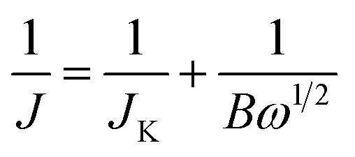
Electrochemical measurements were performed on a Autolab PGSTAT30 electrochemical workstation with a three-electrode system. A glassy carbon (GC) rotating disk electrode (RDE) (3 mm diameter, 0.07065 cm2 geometric area) was used as the working electrode. Pt foil electrode was used as the counter electrode. An Ag/AgCl electrode with saturated KCl solution was used as the reference electrode. The electrolyte was 0.1 M aqueous KOH solution, which was purged with N2 or O2 for 30 min prior to electrochemical testing. For the electrode preparation, N-ZTC was dispersed in a mixture of 5 wt% Nafion 112 solution (Fluka), ethanol, and distilled water (volume ratio of 1:1:8) by sonication. 10 μL of 1 mg mL−1 N-ZTC catalyst suspension was transferred onto a GC RDE and dried at 333 K. The catalyst loading was calculated to be 141 μg cm−2. The N-RGO and Pt/C (20 wt% Pt supported on carbon black, Alfar Aesar) control catalysts were prepared by the same method. Cyclic voltammetry (CV) was measured at a scan rate of 100 mV s−1. Linear scan voltammetry (LSV) at various disk rotating rates was also measured using a RDE at a scan rate of 10 mV s−1. The Koutecky–Levich (K–L) plots were deduced from the obtained RDE curves and analyzed at various electrode potentials. The slopes of their linear-fit lines were used to calculate the number of electrons transferred per oxygen molecule (n) on the basis of the K–L equation:where J denotes the measured current density, JK represents the kinetic-limiting current density, and ω is the electrode rotating rate. B can be determined from the slope of K–L plots based on the K–L equation as follows:
| B = 0.2nFC0(D0)2/3(υ)−1/6 |
485 C mol−1), C0 is the bulk concentration of O2 (1.2 × 10⁻⁶ mol cm−3), D0 is the diffusion coefficient of O2 in 0.1 M KOH (1.9 × 10⁻⁵ cm2 s−1), and υ is the kinetic viscosity (0.01 cm2 s−1). The constant 0.2 is adopted when the rotation rate is expressed in rpm.
KPFM measurement
KPFM is a quantitative method to evaluate changes in the electrostatic field of work functions on the surface of solids. The electrostatic force (Fe) between the tip and the sample can be described by the following equation:where z and C are the distance and capacitance between the tip and the sample, respectively. When a bias AC voltage (Vac) and DC voltage (Vdc) are applied to a conductive tip, a voltage difference (ΔV) is generated due to the contact potential difference (CPD) between the tip and the sample. This causes a shift of the frequency and phase in the oscillation of a cantilever, and this phase shift can be described by the following equation:
Thus, if the Vdc signal is extracted from the atomic force microscopy (AFM) oscillation signal using the lock-in technique and a feedback system is employed to provide a signal to nullify the value, Vcpd can be obtained. In our KPFM experiments, we utilized a Bruker Multimode 8 AFM with a conductive non-contact cantilever coated with Pt/Ir. The nominal resonance frequency which was utilized in topography mapping was 75 kHz. Additionally, a 1 kV sinusoidal signal with a frequency of 10 kHz was applied for the CPD measurement.
Results and discussion
Fig. 1a shows a schematic diagram of the synthesis of N-ZTC. In this synthesis, the beta zeolite template is treated with aqueous acetonitrile vapor (71.5 wt%) at 1023 K. The water vapor is added to the carbon source in an attempt to suppress carbon deposition at the external surfaces of the zeolite template, following previous literature.26,28 After carbon deposition, the sample is subsequently heated at 1173 K under a N2 flow in order to obtain carbon products with highly ordered pores. During the heat treatment, the carbon framework is rigidified by shrinkage of the zeolite structure.25–27 This process gave a carbon yield of 300 mg g−1 zeolite. This yield is consistent with the calculated carbon yield assuming that the carbon is evenly deposited throughout the zeolite micropores, and that the carbon density is 1.5 g cm−3.26 | ||
| Fig. 1 (a) Schematic illustration of the synthesis process, (b) SEM image, (c) TEM image and (d) powder XRD pattern of N-ZTC synthesized with aqueous acetonitrile. | ||
The final N-ZTC, liberated from the beta zeolites, exhibits a crystal morphology that strongly resembles zeolite crystals (Fig. 1b and S1†). The highly ordered microporous structure with lattice fringes of 1.1 nm is shown in the TEM image (Fig. 1c). The SEM and TEM observations indicate that the pore structure of zeolites is successfully replicated by the carbons. The high level of carbon replication is supported by the XRD pattern for N-ZTC, which shows well-resolved peaks at 7° and even at 15° (Fig. 1d). The XRD peak positions are almost the same as the (101) diffraction and its second-order diffraction of the beta zeolites, respectively (Fig. S1†). Furthermore, the carbons do not present thick external carbon layers, as was intended by exploiting the effect of water vapor in the carbon deposition process.26,28 This feature is significant in terms of carbon applications because the external carbons can prevent easy diffusion of molecules in and out of porous carbon particles.
Further structural characterization of N-ZTC was carried out using the argon sorption isotherm (Fig. 2). The carbon shows strong adsorption at a P/P0 under 0.1. This indicates that the carbon product is mainly composed of micropores. The micropore size determined using the NLDFT method shows a very sharp distribution around 0.94 nm. The distribution curve also shows pores larger than 1.2 nm. The generation of such large pores could be attributed to incomplete carbon filling31 due to diffusion limitations, as follows: at the beginning of the carbon infiltration process, carbon can be freely deposited in any zeolite cages. As the carbon loading increased, many of the cages become occupied. At this stage, the carbon precursor can only diffuse into the core of the zeolite particle through the available empty cages. According to such diffusion controlled process, the carbon deposition eventually stops at a certain level of carbon loading, leaving some empty cages unfilled. The unfilled cages lead to the generation of pores larger than 1.2 nm. Despite the presence of such large pores, the N-ZTC still has a large micropore volume of 1.4 cm3 g−1, which is more than 90% of the total pore volume. A BET surface area of 1860 cm2 g−1 is achieved.
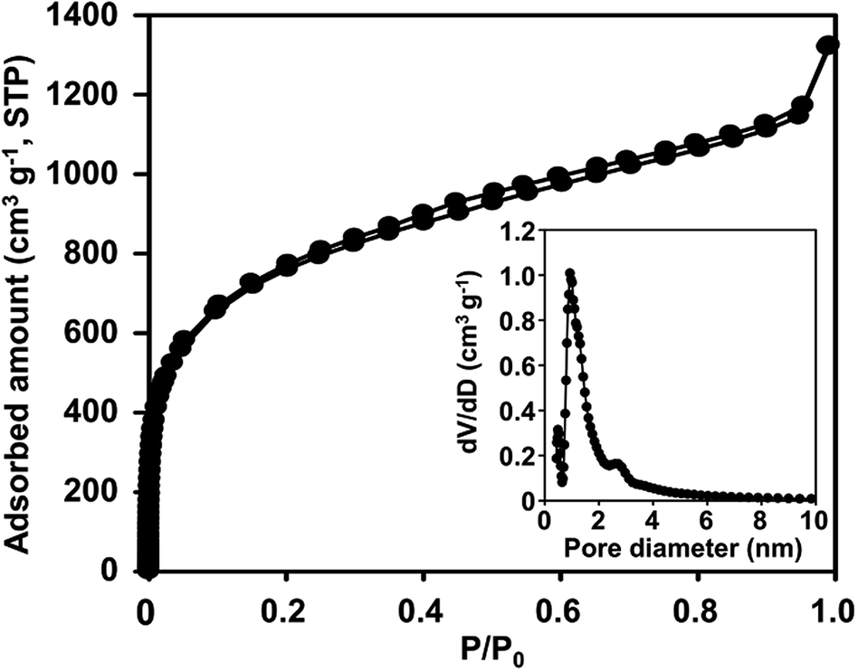 | ||
| Fig. 2 Argon sorption isotherm of N-ZTC synthesized with aqueous acetonitrile at 1023 K (inset: DFT pore size distribution). | ||
We performed XPS analysis of the N-ZTC sample to investigate its chemical composition and nitrogen content. The survey XPS spectrum (Fig. 3a) shows a predominant C1s peak at 284.1 eV together with an O1s peak at 531.8 eV and broad a N1s peak at around 401 eV. The binding energy of the C1s peak corresponds to sp2-hybridized carbon. This is further supported by solid-state 13C CP MAS NMR (Fig. S2†), in which an intense sp2-carbon peak is observed, but no detectable peaks assignable to sp- or sp3-carbons are present. The presence of oxygen atoms might be due to partial oxidation of the carbon framework during the template removal process using aqueous HF/HCl solution.26 As calculated from the XPS spectrum, the nitrogen content is 4.1 wt%. In fact, this value represents the surface nitrogen content as XPS only gives chemical information for particle surfaces. The elemental analysis showed a total nitrogen concentration of 3.8 wt%, which is very close to the surface nitrogen content. These results indicate the homogeneous distribution of nitrogen atoms through the carbon framework. The bonding nature of the nitrogen is revealed by a high-resolution N1s XPS spectrum (Fig. 3b). The complex spectrum can be fitted by four overlapping peaks at 398.5, 400.5, 401.5, and 403.0 eV, which can be assigned to the different states of nitrogen atoms substituted for carbon in the graphene layer, i.e., pyridinic N, pyrrolic N, graphitic N and oxide N, respectively (Fig. 3c).32 The ratio of these four species is 20:15:54:11.
 | ||
| Fig. 3 (a) Survey, (b) N1s XPS spectra of N-ZTC synthesized with aqueous acetonitrile and (c) schematic illustration of N species in graphene structure. | ||
It should be noted that the nitrogen atoms bonded to three carbon atoms (i.e., graphitic N) comprise the major portion (54%) of the total nitrogen. In general, carbon materials with a high level of graphitic N can be only obtained using appropriate carbon precursors with graphitic N functionalities, such as imidazole and azole-based compounds.33,34 For this synthesis, we speculate that the decisive factor increasing the concentration of graphitic N is the presence of water vapor, which acts as a mild oxidant under carbonization conditions. In principle, graphitic N is more stable than other nitrogen functional groups (i.e., pyridinic N, pyrrolic N, and oxide N).35,36 In this regard, pyridinic, pyrrolic, and oxide N are more favorably oxidized than graphitic N by water vapor at high temperature. Hence, formation of the less stable nitrogen species is hindered during carbonization involving water vapor. To clarify the effect of water vapor, N-ZTC was also synthesized using anhydrous acetonitrile as a carbon precursor. XPS analysis of the resultant carbon product (Fig. S3 and Table S1†) shows that 35% of the total N content is graphitic, while 45% is pyridinic. The ratio of the four nitrogen states is markedly different to that in the material synthesized using aqueous acetonitrile. Thus, it was possible to synthesize the N-doped carbons with a high content of graphitic N through carbonization involving water vapor without expensive and hazardous carbon precursors.
The electrocatalytic properties of N-ZTC for the ORR were investigated in a 0.1 M KOH solution using a three-electrode system. First, we quickly surveyed the catalytic activity by CV with a N2- or O2-saturated KOH solution at a scan rate of 100 mV s−1 (Fig. 4a). The CV curve in the O2-saturated electrolyte solution exhibits a distinct cathodic peak at −0.25 V (vs. Ag/AgCl), as opposed to the case with N2 saturation. This quick assessment confirms the electrocatalytic activity for ORR. To further understand the electrocatalytic behavior of N-ZTC in the ORR, RDE voltammetry measurement was performed in an O2-saturated KOH solution at a rotation speed of 1600 rpm and a scan rate of 10 mV s−1. For comparison, we measured the RDE performance of an N-RGO sample and a commercial Pt/C catalyst (20 wt% Pt) under the same conditions. The N-RGO with 4.3 wt% doping concentration was synthesized by thermal treatment of graphene oxide with melamine according to a previous report (Fig. S4 and Table S2†).14 The crystallinity and thickness of the N-RGO sample were consistent with the previous work (Fig. S4†). Fig. 4b shows the resultant polarization curves. The onset potential of N-ZTC (−0.13 V) is even more positive than that of N-RGO (−0.20 V). In terms of diffusion-limited current density, N-ZTC also exhibits higher performance than N-RGO.
 | ||
| Fig. 4 (a) CV curves of N-ZTC modified electrodes in an O2 (or N2)-saturated 0.1 M KOH at a scanning rate of 100 mV s−1, (b) ORR polarization curves of N-ZTC, N-RGO and Pt/C in an O2-saturated 0.1 M KOH with rotating rate of 1600 rpm at a scanning rate of 10 mV s−1, (c) RDE curves of N-ZTC in an O2-saturated 0.1 M KOH with different rotating rates at a scanning rate of 10 mV s−1 (inset: K–L plots deduced from RDE curves of N-ZTC) and (d) the number of electrons transferred as a function of potential from N-ZTC, N-RGO and Pt/C. | ||
Recently, Guo et al. systematically demonstrated that nitrogen atoms doped into pyridinic sites are decisive to create catalytic active site for ORR.37 According to the previous literature, the higher performance of N-ZTC is inconsistent with the fact that the pyridinic N content of N-ZTC is lower than that of N-RGO (Tables S1 and S2†). The discrepancy can be ascribed to the porous structure of N-ZTC. It is apparent that the high current density is due to the high accessibility of the reactants to the catalytic active sites in the porous structure.15 However, the positive shift of the onset potential is difficult to be explained by only the accessibility. Instead, the potential shift could arise from the highly tortuous or curved carbon surfaces with sp2-carbon bonding nature. It is known that a surface curvature in graphene can induce a charge density difference between adjacent carbon atoms.38 Indeed, ZTC sample without N-doping exhibited moderate electrocatalytic ORR activity with the onset potential of −0.15 V (Fig. S5†). As compared to the commercial Pt/C catalyst, the N-ZTC is not yet better in terms of the onset potential but exhibits a comparable diffusion-limited current density.
The detailed kinetic parameters, such as the electron transfer number and kinetic current density (JK), were also studied using K–L plots. The ORR polarization curves were measured at various disk rotation rates ranging from 600 to 3000 rpm (Fig. 4c and S6†). In the K–L plots, obtained from the RDE curves, the diffusion-limited current densities and the rotation speed present a linear correlation (inset of Fig. 4c), which indicates that the reaction is first-order in terms of the concentration of dissolved oxygen molecules.39 The electron transfer number, determined from the slope of the K–L plots, indicates that N-ZTC catalyzes the oxygen reduction via an almost four-electron pathway (Fig. 4d). As compared to N-RGO, notably, the electron transfer number is higher over a wide range of potential. In addition, N-ZTC also exhibits a higher JK value, a reciprocal of the y-intercept in the K–L plots (Fig. 4c and S6†), than N-RGO. These results indicate that higher selectivity toward total oxygen reduction is achieved using the porous carbon structure.
The ORR activity of N-doped carbon is known to be strongly correlated with the work function on the catalyst surface.23 In this respect, we measured the local work functions of the catalysts using KPFM to confirm the ORR activity. KPFM is one of the extended techniques of AFM, where the cantilever scans deviation of voltages between a conductive tip and a sample while bias voltage is applied. The contact potential difference (CPD) image, obtained in this manner, can show a contrast corresponding to the local work function variation of the sample.40–42 In our measurement, the N-ZTC and N-RGO were loaded on an Au (111)-coated silicon wafer using a drop-casting method (Fig. S7†). The Au (111) substrate was used as a reference for the calculation of the work function. In the CPD images, the two samples show a brighter contrast than the Au-coated substrate. This indicates that the work functions of the two samples are lower than that of the Au (111) substrate (4.9 eV).43 As shown in the line profile acquired along the white dashed line in the CPD images, the CPD value of N-ZTC is 60 mV. On the other hand, that of the N-RGO is 35 mV. Both CPD values are well reproduced within the measurement error limit of 5 mV. From the CPD values, the work function values for N-ZTC and N-RGO are calculated to be 4.840 and 4.865 eV, respectively. Here, it is noteworthy that we have a work function value for N-ZTC that is even lower than that of N-RGO sheets. This may be related to a surface curvature in the N-ZTC framework, similar to the case of graphene sheets.44,45
Conclusions
In summary, we synthesized a nitrogen-doped zeolite-templated carbon (N-ZTC) containing 4 wt% N, using acetonitrile and a beta zeolite template. The N-ZTC exhibited zeolite-inherited, highly ordered, microporous texture and a BET surface area of 1860 m2 g−1. This microporous carbon exhibited superior ORR catalytic performance to N-RGO, in terms of both current density and the onset potential. Characterization by KPFM indicated that the N-ZTC had a low work function compared to that of planar graphene nanosheets. We do not yet have direct evidence; however, the high ORR performance seems to be due to nitrogen atoms incorporated into a curved graphene-like framework. Currently, high-quality N-ZTC materials are available only in small quantities in a laboratory scale. A breakthrough in research on ZTC and N-ZTC may follow if this synthesis limitation is resolved.Acknowledgements
This work was supported by IBS-R004-D1.Notes and references
- P. Vanýsek, in CNC Handbook of Chemistry and Physics, ed. D. R. Lide, CRC Press, Boca Raton, Florida, 90th edn, 2009, p. 23, section 8 Search PubMed.
- S. Mukejee, S. Srinivasan, M. P. Soriaga and J. Mcbreen, J. Electrochem. Soc., 1995, 142, 1409 CrossRef.
- K. Kinoshita, J. Electrochem. Soc., 1990, 137, 845 CrossRef CAS.
- B. C. H. Steele and A. Heinzel, Nature, 2001, 414, 345 CrossRef CAS PubMed.
- M. Winter and R. J. Brodd, Chem. Rev., 2004, 104, 4245 CrossRef CAS PubMed.
- U. A. Paulus, A. Wokaun, G. G. Scherer, T. J. Schmidt, V. Stamenkovic, V. Radmilovic, N. M. Markovic and P. N. Ross, J. Phys. Chem. B, 2002, 106, 4181 CrossRef CAS.
- J. Zhang, K. Sasaki, E. Sutter and R. R. Adzic, Science, 2007, 315, 220 CrossRef CAS PubMed.
- S. Maldonado and K. J. Stevenson, J. Phys. Chem. B, 2005, 109, 4707 CrossRef CAS PubMed.
- T. Kondo, S. Casolo, T. Suzuki, T. Shikano, M. Sakurai, Y. Harada, M. Saito, M. Oshima, M. I. Trioni, G. F. Tantardini and J. Nakamura, Phys. Rev. B: Condens. Matter Mater. Phys., 2012, 86, 35436 CrossRef.
- L. Lai, J. R. Potts, D. Zhan, L. Wang, C. K. Poh, C. Tang, H. Gong, Z. Shen, J. Lin and R. S. Ruoff, Energy Environ. Sci., 2012, 5, 7936 CAS.
- J. C. Meyer, S. Kurasch, H. Park, V. Skakalova, D. Künzel, A. Groß, A. Chuvilin, G. Algara-Siller, S. Roth, T. Iwasaki, U. Starke, J. H. Smet and U. Kaiser, Nat. Mater., 2011, 10, 209 CrossRef CAS PubMed.
- K. Gong, F. Du, Z. Xia, M. Durstock and L. Dai, Science, 2009, 323, 760 CrossRef CAS PubMed.
- Y. Wang, X. Wang and M. Antonietti, Angew. Chem., Int. Ed., 2012, 51, 68 CrossRef CAS PubMed.
- Z. H. Sheng, L. Shao, J. J. Chen, W. J. Bao, F. B. Wang and X. H. Xia, ACS Nano, 2011, 5, 4350 CrossRef CAS PubMed.
- R. Liu, D. Wu, X. Feng and K. Müllen, Angew. Chem., 2010, 122, 2619 CrossRef.
- T. Sharifi, G. Hu, X. Jia and T. Wägberg, ACS Nano, 2012, 6, 8904 CrossRef CAS PubMed.
- K. Ghosh, M. Kumar, T. Maruyama and Y. Ando, J. Mater. Chem., 2010, 20, 4128 RSC.
- S. Ni, Z. Li and J. Yang, Nanoscale, 2012, 4, 1184 RSC.
- J. Liang, Y. Jiao, M. Jaroniec and S. Z. Qiao, Angew. Chem., Int. Ed., 2012, 51, 11496 CrossRef CAS PubMed.
- D. Geng, Y. Chen, Y. Chen, Y. Li, R. Li, X. Sun, S. Ye and S. Knights, Energy Environ. Sci., 2011, 4, 760 CAS.
- Y. Li, Y. Zhao, H. Cheng, Y. Hu, G. Shi, L. Dai and L. Qu, J. Am. Chem. Soc., 2012, 134, 15 CrossRef CAS PubMed.
- L. Qu, Y. Liu, J. Baek and L. Dai, ACS Nano, 2010, 4, 1321 CrossRef CAS PubMed.
- J. Y. Cheon, J. H. Kim, J. H. Kim, K. C. Goddeti, J. Y. Park and S. H. Joo, J. Am. Chem. Soc., 2014, 136, 8875 CrossRef CAS PubMed.
- T. kyotani, T. Nagai, S. Inoue and A. Tomita, Chem. Mater., 1997, 9, 609 CrossRef CAS.
- H. Nishihara, P. X. Hou, L. X. Li, M. Ito, M. Uchiyama, T. Kaburagi, A. Ikura, J. Katamura, T. Kawarada, K. Mizuuchi and T. Kyotani, J. Phys. Chem. C, 2009, 113, 3189 CAS.
- K. Kim, M. Choi and R. Ryoo, Carbon, 2013, 60, 175 CrossRef CAS.
- H. Nishihara, Q. H. Yang, P. X. Hou, M. Unno, S. Yamauschi, R. Saito, J. I. Paredes, A. MartÍnez-Alonso, J. M. D. Tascón, Y. Sato, M. Terauchi and T. Kyotani, Carbon, 2009, 40, 1220 CrossRef.
- K. Hata, D. N. Futaba, K. Mizuno, T. Namai, M. Yumura and S. Iijima, Science, 2004, 306, 1362 CrossRef CAS PubMed.
- Z. Yang, Y. Xia and R. Mokaya, J. Am. Chem. Soc., 2007, 129, 1673 CrossRef CAS PubMed.
- C. O. Ania, V. Khomenko, E. Raymundo-Piñero, J. B. Parra and F. Béguin, Adv. Funct. Mater., 2007, 17, 1828 CrossRef CAS.
- Z. Ma, T. Kyotani and A. Tomita, Carbon, 2002, 40, 2367 CrossRef CAS.
- D. Wei, Y. Liu, H. Zhang, L. Huang and G. Yu, Nano Lett., 2009, 9, 1752 CrossRef CAS PubMed.
- P. Bhunia, E. Hwang, Y. Yoon, E. Lee, S. Seo and H. Lee, Chem.–Eur. J., 2012, 18, 12207 CrossRef CAS PubMed.
- K. Fahsi, S. G. Dutremez, A. Vloux and L. Viau, J. Mater. Chem. A, 2013, 1, 4451 CAS.
- C. Chen, J. Zhang, B. Zhang, C. Yu, F. Peng and D. Su, Chem. Commun., 2013, 49, 8151 RSC.
- R. Arrigo, M. Hävecker, R. Schlögl and D. S. Su, Chem. Commun., 2008, 4891 RSC.
- D. Guo, R. Shibuya, C. Akiba, S. Saji, T. Kondo and J. Nakamura, Science, 2016, 351, 361 CrossRef CAS PubMed.
- E. J. Duplock, M. Scheffler and P. J. D. Lindan, Phys. Rev. Lett., 2004, 92, 225502 CrossRef PubMed.
- S. Treimer, A. Tang and D. C. Johnson, Electroanalysis, 2002, 14, 165 CrossRef CAS.
- W. Melitz, J. Shen, A. C. Kummel and S. Lee, Surf. Sci. Rep., 2011, 66, 1 CrossRef CAS.
- W. Lee, U. N. Maiti, J. Lee, J. Lim, T. Han and S. Kim, Chem. Commun., 2014, 50, 6818 RSC.
- H. Hoppe, T. Glatzel, M. Niggermann, A. Hinsch, M. C. Lux-Steiner and N. S. Sariciftci, Nano Lett., 2005, 5, 269 CrossRef CAS PubMed.
- P. Ravirajan, S. A. Haque, J. R. Durrant, D. Poplavskyy, D. D. C. Bradley and J. Nelson, J. Appl. Phys., 2004, 95, 1473 CrossRef CAS.
- X. Sha and B. Jackson, Surf. Sci., 2002, 496, 318 CrossRef CAS.
- P. Ruffieux, O. Gröning, M. Bielmann, P. Mauron, L. Schlapbach and P. Gröning, Phys. Rev. B: Condens. Matter Mater. Phys., 2002, 66, 245416 CrossRef.
Footnote |
| † Electronic supplementary information (ESI) available: SEM and XRD data of beta-zeolite template, 13C CP MAS solid-state NMR spectrum of N-ZTC, N1s XPS information of N-ZTC synthesized with anhydrous acetonitrile, XRD, Raman and N1s XPS information of N-RGO, electrocatalytic ORR data of ZTC and N-RGO and KPFM results of N-ZTC and N-RGO. See DOI: 10.1039/c6ra08085e |
| This journal is © The Royal Society of Chemistry 2016 |