Aerosol-assisted in situ synthesis of iron–carbon composites for the synergistic adsorption and reduction of Cr(VI)

Ling Aia, Jiawei Hea, Yiyan Wanga, Chaoliang Weib and Jingjing Zhan*a
aSchool of Food and Environment, Dalian University of Technology, Panjin, 124221, P. R. China. E-mail: jingjingzhan@dlut.edu.cn; Tel: +86-427-2631789
bSchool of Chemistry, Dalian University of Technology, Dalian, 116024, P. R. China

Received 28th March 2016 , Accepted 6th June 2016

First published on 7th June 2016


Abstract

In this work, we adopted newly developed spherical iron–carbon composites to remove hexavalent chromium (Cr(VI)) from contaminated water. These composites were prepared in situ through a facile aerosol-assisted process followed by an economic carbothermal reduction using only common sugar and ferrous sulfate as starting materials, and then characterized by SEM, TEM, XRD and BET. Because of the diverse functions of carbon and nanoscale zero-valent iron, aerosol-assisted iron–carbon composites show synergistic adsorption and reaction towards a more efficient removal of Cr(VI). Under identical experimental conditions, such composites exhibit the highest removal efficiency compared to other materials including nanoscale zero-valent iron particles, aerosol-assisted carbon and their physical mixture. Meanwhile, X-ray photoelectron spectroscopy analysis proved as-prepared iron–carbon composites could effectively transform Cr(VI) to much less toxic trivalent chromium (Cr(III)). These iron–carbon composites produced at low cost show significant potential for the remediation of groundwater and sediment contaminated with heavy metals such as Cr(VI).

1. Introduction

Hexavalent chromium (Cr(VI)) is a frequently detected groundwater contaminant originating from various industrial processes such as leather tanning, pigment synthesis, electroplating and metal finishing.1,2 Because it is a potential carcinogen or mutagen to most organisms, Cr(VI) has been listed as one of the priority pollutants and its concentration in drinking water has been regulated in many countries. For instance, the United States Environmental Protection Agency has set the maximum contaminant level for Cr(VI) into surface waters as 0.1 mg L−1 and in domestic water supplies to be 0.05 mg L−1.3 Therefore, elimination of Cr(VI) from groundwater has received significant attention from both academic and industrial societies.4

Various technologies have been employed for Cr(VI) removal, such as adsorption (especially using carbon materials),5–8 ecological remediation9 and chemical redox.10 Among these techniques, using nanoscale zero-valent iron (NZVI) particles represents a promising approach because of their strong reducing ability, fast reaction kinetics and the fact that they can suspend in a slurry and thereby can be directly injected into the contaminated sites.11,12 Here, NZVI serves as an electron donor, converting Cr(VI) to its lower oxidation state trivalent chromium (Cr(III)), which is 300–500 times less toxic.13–18 Moreover, Cr(III) can be precipitated as sparingly soluble Cr(OH)3 (Ksp = 6.3 × 10⁻³¹) at high pH and thus could be completely removed as solid waste.

However, NZVI particles suffer from their inherent aggregation due to their characteristics of a high surface energy and magnetization, which results in the decay of their reactivity that is intrinsically necessary for the practical application.19–21 To address this problem, two kinds of modifications including soft coatings and solid supports were generally used. For example, attachment of a layer of organic species such as carboxymethyl cellulose (CMC),22 and poly(acrylic acid) (PAA),23 or triblock copolymers24 to the NZVI particle surface effectively improved the stability of NZVI particles owing to steric hindrance and/or electrostatic repulsion. However, the drawback of this approach is that these soft coating layers resisted the mass transfer and thus don't help promoting NZVI reactivity.25 In another option, solid materials such as activated carbon,26 bentonite,27 multiwalled carbon nanotubes28 and montmorillonite29 were used as supports to generate such NZVI-support composites. Although these supports could successfully restrict the aggregation of NZVI particles, the incipient-wetness technique as the most widely used method involved a number of processing steps. Meanwhile, the loading amount was determined by the pore volume or surface area of the support and thus only limited NZVI particles were supported.

To enhance the performance of NZVI particles, in our previous work we proposed a concept of using multifunctional iron-based composites such as Fe–Silica, Fe–hydrothermal carbon and Fe-aerosol carbon in replace of bare NZVI particles for environmental remediation.30–32 Furthermore, we developed a facile aerosol-assisted technology followed by a simple carbothermal reduction for in situ synthesis of iron–carbon composites that have the requisite characteristics for groundwater remediation.33 These iron–carbon composites have been tested toward the dechlorination of chlorinated hydrocarbons such as trichloroethylene (TCE). In addition to preventing the aggregation of NZVI particles and enhancing the transport ability, the main feature of composites is hydrophobic carbons high effectiveness in adsorbing TCE, thereby increasing local concentrations of TCE in the vicinity of the NZVI particles and facilitating reaction.32 However, only one case study is not sufficient to demonstrate the aerosol-assisted iron–carbon composites are as versatile as NZVI particles considering various contaminants with different physical and chemical properties in groundwater. Hence, investigating the performance of these particles in the removal of other contaminants such as heavy metals becomes extremely important.

A synergistic effect between adsorption and reaction towards a more efficient reaction in water treatment can only be achieved when both components play complementary roles. Although the carbon component of the aerosol-assisted iron–carbon composites exhibited the ability to adsorb organic contaminants through dipole–dipole interaction and hydrophobic effects, there has been no report concerning inorganic contaminants such as heavy metal ions which may also have an affinity with aerosol-assisted carbon materials through different mechanisms such as physical interaction and forming chemical bonds.34 Hence, our objective in this paper was to determine whether the aerosol-assisted iron–carbon composites could provide dual functions of adsorption coupling with reaction in the removal Cr(VI) from the solution. Here, we kept the merits of our earlier work to use the aerosol-based technology to in situ synthesize iron–carbon composites but switching to use a low-cost atomizer. Characterization of the obtained composites was carried out by SEM, TEM, XRD and BET. X-ray photoelectron spectroscopy (XPS) analysis was applied to determine the predominant mechanism of the removal of Cr(VI), and the influencing factors including solution pH, the initial contaminant concentration and composite dosage were investigated in detail. To confirm the synergistic effect, parallel experiments using a mixture of separated NZVI and carbon, NZVI and carbon were tested.

2. Experimental section

2.1. Chemicals and materials

All chemicals were reagent grade and used as received. Ferrous sulfate heptahydrate (FeSO4·7H2O) and sucrose were purchased from Tianjin Kermel Chemical Reagent Co., Ltd.; potassium dichromate (K2Cr2O7) and nanoscale ferric oxide (Fe2O3) powder were supplied by Tianjin Damao Chemical Reagent Factory; concentrated sulfuric acid (H2SO4), concentrated hydrochloric acid (HCl) and sodium hydroxide (NaOH) were purchased from Chinese Sinopharm.

2.2. In situ synthesis of iron–carbon composites

Iron–carbon composites (hereafter designated as Fe–C) were in situ prepared through an aerosol-assisted process following by a carbothermal reduction. The procedure is similar to our earlier work,33 but the difference is a relative inexpensive commercial atomizer with more simple structure (HRH WAG-3, Beijing Huironghe Company) was firstly used, making the whole process more economic and convenient. In our experiments, 6.0 g of sucrose and 5.0 g of FeSO4·7H2O as starting materials were firstly dissolved in 50 mL of deionized water. Here, iron sulfate other than iron chloride was chosen to avoid the corrosion of the atomizer made of stainless steel. With the flow of carrier gas (N2), the precursor solution in the atomizer was broken down into aerosol droplets, which were then pass through a heating zone where the temperature was held at 1000 °C. The flow rate of the carrier gas N2 was controlled at 3 L min−1, which is considered as an important factor in determining the size distribution of the product. The resulting black powder, which hereafter referred to as Fe3O4–C, was collected by filter paper maintained at 100 °C to facilitate drying. In the carbothermal treatment, the above-mentioned Fe3O4–C powder was placed in a crucible boat in a quartz tube, which was kept at 1000 °C for 3 h in a tube furnace, allowing a “self-redox” reaction between Fe3O4 and C occur. The whole process is always under the protection of flowing nitrogen.

In addition, aerosol-assisted bare carbon particles as control were prepared following our previous work,32 where 2% w/v of concentrated H2SO4 was used as a dehydration catalyst but without the use of the iron precursor.

2.3. Characterizations and measurements

The morphological characterizations of Fe–C composites were performed using a Hitachi-4800 field emission scanning electron microscope (FE-SEM) and a Tecnai-20 transmission electron microscope (TEM). X-ray diffraction (XRD) patterns were obtained on a Shimadzu-7000S XRD equipped with a Cu-Kα radioactive source (λ = 0.154 nm) at 40 kV/20 mA. Each profile was collected in the 2θ range from 5° to 90° at a scanning speed of 5° min−1. Nitrogen adsorption–desorption measurements were examined at 77 K on an automatic gas adsorption instrument (Quantachrome, Autosorb Iq-2, USA). Specific surface areas were determined with the Brunauer–Emmett–Teller (BET) method, and pore size distribution was calculated by Barrett–Joyner–Halenda (BJH) model. X-ray photoelectron spectroscopy (XPS) was employed to assess the chemical state and surface composition of the materials with a Thermo ESCALAB 250Xi using Al Kα (1486.6 eV, 15 kV, 10.8 mA) as X-ray source for excitation.

2.4. Cr(VI) removal experiments

The removal of Cr(VI) was carried out in batch mode at room temperature and the pH values of the solutions were adjusted with 0.1 mol L−1 NaOH and 0.1 mol L−1 HCl. To each vial, 10 mL of Cr(VI) solution at a known concentration and desired amount of Fe–C composites were added, followed by mixing on a vortex. At certain time intervals, 1.2 mL of aliquots were taken out and centrifuged for 2 min at 15[thin space (1/6-em)]000 rpm to obtain solid–liquid separation. The concentration of Cr(VI) in the supernatants was determined using the 1,5-diphenylcarbazide method with a UV-vis spectrophotometer (5200 PC, China) at wavelength of 540 nm. All the experiments were carried out in duplicate and the averages results were recorded. The removal efficiency of Cr(VI) was calculated as the following:
image file: c6ra07953a-t1.tif
where C0 and Ct (mg L−1) are the concentrations of Cr(VI) in the aqueous solution at the initial time and time t (min), respectively.

In order to investigate the role that carbon and NZVI played in the aerosol-assisted Fe–C composites, NZVI (gas reduction from nano-Fe2O3 powder), aerosol-assisted carbon and a mixture of separated NZVI and aerosol-assisted carbon (designated as Fe + C) were all used in batch experiments with the same iron and carbon contents.

3. Results and discussion

3.1. Synthesis and characterization of Fe–C composites

Fig. 1 illustrates the schematic of the aerosol reactor which mainly comprises of three parts: an atomizer, a heating zone and a filter. In the atomizer, a homogeneous aqueous solution containing sucrose and ferrous sulfate was sucked up from the container due to Venturi effect and then was broken into small aerosol droplets due to the collision by a carrier gas flowing with a high velocity. During these aerosol droplets passing through the heating zone, the precipitation and phase transition of iron species is concomitant with the dehydration and carbonization of sucrose under high temperature conditions leading to the formation of Fe3O4–C composites. In the subsequent carbothermal reduction process, a “self-redox” reaction occurs within these Fe3O4–C composites, where the entrapped Fe3O4 particles are thermally reduced by carbon frameworks, resulting in the formation of final product Fe–C composites. The final weight percentage of zero-valent iron in the Fe–C composites was approximately 40%. This content was determined by weighing the residual solid (Fe2O3) of a known mass of Fe–C composites after calcination under 500 °C in the air for 4 h. We notice a more inexpensive medical nebulizer was used as the atomizer to reduce the cost in our recent work,35 but low productivity and broad particle size distributions may impede its application.
image file: c6ra07953a-f1.tif
Fig. 1 The schematic of aerosol equipment.

SEM and TEM images as shown in Fig. 2 indicate Fe–C composites are spherical with size range in the order of 100 nm to 1 μm, characteristic of particles synthesized through aerosol-based technology. The SEM image (Fig. 2a) appears to show lots of small species, which were further confirmed as NZVI particles by the subsequent XRD and XPS characterizations, have been incorporated in the composites which maintain a porous morphology. The TEM (Fig. 2b) further confirms the presence of NZVI particles in the porous carbon spheres, where NZVI particles symbolized by darker spots show enhanced contrast due to the higher electron density of iron. The phase states of iron species are verified by the XRD patterns shown in Fig. 3a. For particles collected directly from the aerosol process prior to the carbothermal treatment, magnetite peaks dominate the pattern indicating that the starting material FeSO4 transformed primarily to Fe3O4 during aerosolization. The transition of iron oxides to element iron occurred in the carbothermal step controlled by temperature. When the temperature was increased from 400 to 700 °C, partially reduction of magnetite took place and FeO was the existing form of iron. Furthermore, the desired zero-valent iron was obtained under 1000 °C which can be proved by strong diffraction peaks at 2θ of 45°, 65° and 82°. Nitrogen adsorption–desorption isotherms measured at 77 K for Fe–C composites and bare aerosol-assisted carbon particles are presented in Fig. 4a. Obviously, Fe–C composites exhibit a IV-type isotherm with a hysteresis loop, associating with their mesoporous structure in agreement with the TEM image. In contrast, bare carbon particles show a I-type isotherm as a result of micropores inside. The disparity in pore structure is further confirmed from the BJH pore size distribution illustrated in Fig. 4b. Apparently, the pores in Fe–C composites are larger and various with the peaks in the distribution mainly centered at 2.1 nm, 2.5 nm and 3.8 nm. It should be noted that the evolution of pore structure from micropores to mesopores led to a distinct decrease in BET surface area from 810 to 163 m2 g−1. However, pore volume was increased as a result of the pore expansion. The porosity of Fe–C composites is desired and will ensure the entry of contaminants to contact the iron species within porous carbon matrixes in Fe–C composites.


image file: c6ra07953a-f2.tif
Fig. 2 SEM (a) and TEM (b) images of aerosol-assisted Fe–C composites.

image file: c6ra07953a-f3.tif
Fig. 3 XRD patterns of particles without and with carbothermal treatment under various temperatures (400 °C, 700 °C and 1000 °C).

image file: c6ra07953a-f4.tif
Fig. 4 Nitrogen adsorption–desorption isotherms (a) and the BJH pore size distribution derived from the desorption branch of the isotherm (b) for aerosol-assisted Fe–C composites and bare carbon nanospheres.

3.2. Synergistic effects in the removal of Cr(VI)

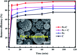
The performance of aerosol-assisted Fe–C composites in the removal of Cr(VI) is presented in Fig. 5, where other three types of materials, including NZVI particles, aerosol-assisted carbon particles and a physical mixture of separated NZVI and aerosol-assisted carbon (Fe + C), are compared under identical experimental conditions. In the experiments, simulated wastewater containing Cr(VI) with the initial concentration at 10 mg L−1 was chosen. To keep the dosages of iron and carbon same, 10 mg of Fe–C composites (40% is Fe and 60% is carbon), 10 mg of Fe + C mixture (Fe[thin space (1/6-em)]:[thin space (1/6-em)]C = 4[thin space (1/6-em)]:[thin space (1/6-em)]6), 4 mg of NZVI and 6 mg of aerosol-assisted C were used individually. It was evident that all kinds of materials were effective in the removal of Cr(VI) to some extent, but an obvious growth was observed for Fe–C composites. Within first 5 min, 91 ± 2% Cr(VI) ions was removed by Fe–C composites and the final removal efficiency over a 2 h reaction time was able to arrive 99%, which meant that the concentration of Cr(VI) has been reduced to 0.1 mg L−1. In contrast, for carbon and NZVI alone, the removal efficiencies were only 63 ± 3% and 68 ± 2% in first 5 min due to adsorption and reduction respectively, and the residual concentrations of Cr(VI) were still at 2.5 mg L−1 and 1.7 mg L−1 after being treated for 2 h. It is worth to note that the Fe + C mixture showed a greater capacity for removal of Cr(VI) than individual NZVI or carbon, and the removal efficiency reached 81 ± 3% and 89 ± 1% in 5 min and 2 h, but was lower than aerosol-assisted Fe–C apparently. This observation is consistent with the proposed idea that it is not the simple additive but synergistic effects of adsorption together with reaction for Fe–C composites in the removal of Cr(VI), where adsorption concentrated Cr(VI) in the vicinity of the NZVI particles and thus facilitated reaction. This finding is in agreement with our previous work in the remediation of trichloroethylene.32 The above improvements in removal efficiency indicated that Fe–C composites had potential advantages in Cr(VI) removal. Comparing the removal efficiency with the previous studies28,36–39 (as shown in Table 1), the prepared aerosol-assisted Fe–C composites were comparable with many other iron–carbon composites reported in the literature.
image file: c6ra07953a-f5.tif
Fig. 5 A comparison on Cr(VI) removal efficiencies by Fe–C, Fe + C, Fe and C under the condition of pH = 5 and the initial Cr(VI) concentration of 10 mg L−1 (10 mg Fe–C, 10 mg Fe + C, 4 mg Fe and 6 mg C).
Table 1 Removal efficiencies of different materials in the treatment of 10 mg L−1 Cr(VI)
Materials Dosage (mg) Initial pH Removal efficiency Reference
Aerosol-assisted Fe–C 10 5 99% This study
Fe/mesoporous carbon 10 5 97% 28
NZVI–multiwalled carbon nanotube 15 7 98% 36
Activated carbon/Fe 10 2 99% 37
Fe3O4/graphene oxide 20 7.5 95% 38
Fe-modified activated carbon 15 2 99% 39


The function of reaction of Fe–C composites was further proved by X-ray photoelectron spectroscopy. For the chromium spectra shown in the Fig. 6, the photoelectron peaks for the chromium 2p3/2 and 2p1/2 centered at 577.1 and 587.6 eV, respectively, and both were similar to the binding energies of Cr(III)-containing materials.21,36 This data demonstrated that adsorbed Cr(VI) anions were eventually reduced to Cr(III) after exposure to aerosol-assisted Fe–C composites, indicating that the Cr(VI) removal process by Fe–C composites involved the reduction of Cr(VI) into Cr(III) combining the sorption. However, bands of Cr(III) appeared in the XPS spectra are not significantly strong even though batch experiments had shown that a mass of Cr(VI) was removed after contact with aerosol-assisted Fe–C composites. The reason was probable that the reduction of Cr(VI) occurred on the surface of iron particles, which are mainly entrapped in the interior of the composites. However, XPS can only provide information about surface states since it is dependent on the detection of the emitted photoelectron. Hence, it is unlikely that XPS is able to detect the state of Cr(III) when it locates in the interior of Fe–C composites. In addition, an excessive dosage of Fenton's reagent was used to re-oxidize the supernatant to confirm if any reduced Cr(III) remained in the solution phase according to the previous method.40 The fact that no Cr(VI) was detected after re-oxidation further validates the immobilization efficiency of Cr(III) by Fe–C composites.


image file: c6ra07953a-f6.tif
Fig. 6 XPS full survey (a) and Cr 2p spectrum (b) for Fe–C composites after Cr(VI) removal. For comparison, the Cr 2p spectrum of before reaction is shown.

3.3. Effect of the pH value

The initial pH of contaminated water is an important controlling parameter in the removal of Cr(VI). Considering the pH value of typical natural groundwater ranging from 5.0 to 9.0,28 we chose the range of pH 5–10 to evaluate the removal efficiency of Fe–C composites in the present study. The results in Fig. 7a show that pH has a direct effect on the Cr(VI) treatment, where the removal efficiency decreased with the increase of initial pH. Here, we found 99%, 91%, 82%, 79%, 77% of Cr(VI) ions were removed over a 2 h reaction time under the conditions of pH at 5, 6, 7, 8, 10, respectively. The fact that Fe–C composites are more effective under the acidic condition could be attributed to the reasons involving two aspects. On the one hand, the pH impact on Cr(VI) removal is largely associated with the Cr(VI) chemistry in the solution and the surface property of the composites. Although the existing forms of Cr(VI) ion in aqueous solutions vary with pH, all of them are anions including HCrO4, CrO42− and Cr2O72−. Since the zero point of charge of Fe–C composites was tested to be 6.1, the surface of Fe–C composites was positively charged at lower pH leading to the electrostatic attraction between Cr(VI) and the composites. On the other hand, a large quantity of H+ in acidic condition could enhance the reaction rate of iron, which accelerated the reduction of Cr(VI) to Cr(III) according to the following processes:
 
2HCrO4 + 3Fe0 + 14H+ → 3Fe2+ + 2Cr3+ + 8H2O (1)
 
HCrO4 + 3Fe2+ + 7H+ → 3Fe3+ + Cr3+ + 4H2O (2)

image file: c6ra07953a-f7.tif
Fig. 7 Effects of the initial pH on Cr(VI) removal efficiency of Fe–C composites (initial Cr(VI) concentration: 10 mg L−1; Fe–C dosage: 10 mg) (a) and Cr(VI) removal efficiencies under the different pH for various materials including Fe–C, Fe + C, Fe and C (b).

Meanwhile, we notice that the removal efficiency did not significantly differ under the neutral and alkaline conditions (decreased by 5% from pH 7 to 10) compared to acidic condition (decreased by 17% from pH 5 to 7). It may be because the concentration of H+ is the main constraint factor in the removal of Cr(VI) for Fe–C composites, while the effect from the competition between chromium ions and OH relatively plays a small role. In addition, effects from the pH value on Cr(VI) removal efficiencies for other types of materials were also investigated. As shown in Fig. 7b, the removal efficiencies of all materials depend strongly on pH and all of them were fairly higher in the acidic condition. It is worth to note that the lowest removal efficiency for Fe–C composites (pH = 10) is still 77%, comparable to that of bare aerosol-assisted carbon (76%) under the optimal condition (pH = 5), showing its potential application in heavy metal removal over a wide pH range.

3.4. Effects of Fe–C composites loading and initial Cr(VI) concentration

Fig. 8a compared the removal efficiencies in the treatment of Cr(VI) when different amounts of Fe–C composites were employed. In order to avoid the leveling effect, here we used a contaminated solution with 25 mg L−1 of Cr(VI), higher than 10 mg L−1 in the previous section. Although we did not observe significant difference in the removal efficiency for the first 5 min, there is an apparent decrease from 98% to 94%, 91%, 85% and finally 82% after 2 h contact time when the dosage of Fe–C composites was reduced from 2 g L−1 to 1.5, 1.0, 0.75 and finally 0.5 g L−1 respectively, implying a finite number of reaction sites and adsorption sites for Fe–C composites. Meanwhile, the effect of initial Cr(VI) concentration on removal efficiency was investigated in the range of 10–50 mg L−1 as shown in Fig. 8b. Obviously, the removal percentages of Cr(VI) decreased as an increase in the initial Cr(VI) concentration. The Cr(VI) removal efficiency was 99% at 10 mg L−1 and decreased to 90%, 89% and 81% when the initial Cr(VI) concentration reached 15, 25 and 50 mg L−1, respectively. Consistent with the synergistic effects, data presented in Fig. 8 could not be fitted well to pseudo-first-order model because the overall mechanism was more complicated than a simple chemical reaction or adsorption. It is not clear that Cr ions are expected to preferentially interact carbon parts or NZVI parts of Fe–C composites in our experiments, but we suppose all the Cr(VI) ions were transformed to Cr(III) through iron surface eventually, which was supported by aforementioned XPS analysis.
image file: c6ra07953a-f8.tif
Fig. 8 Effects of Fe–C composites dosage (a) and the initial Cr(VI) concentration on Cr(VI) removal efficiency (b).

4. Conclusions

Spherical mesoporous iron–carbon nanocomposites were in situ fabricated successfully through a two-step method. Both the aerosol-assisted process and the following carbothermal reduction process are simple and inexpensive, holding great potential to be scaled up. These composites exhibit dual functionalities in the removal of Cr(VI), where carbon matrixes allow adsorption of Cr(VI) and immobilization of iron nanoparticles prevents zero-valent nanoiron aggregation with maintenance of reactivity. Meanwhile, these composites display the highest efficiency compared to other materials including a physical mixture of separated NZVI and aerosol-assisted carbon, NZVI and aerosol-assisted carbon, which indicates the synergistic effect played a role in the removal of Cr(VI). XPS analysis proved Fe–C composites could effectively transform Cr(VI) to Cr(III), which is much less toxic. Furthermore, the effects of pH, materials dosage and the initial Cr(VI) concentration on the removal performance were studied for the future practical application. Meanwhile, we consider there is still a lot of work including lower Cr(VI) concentration, the effect of interferences, the recovery and the reuse of the materials that should be done in our future studies.

Acknowledgements

We sincerely thank Dr Yanqiang Huang at Dalian Institute of Chemical Physics for his assistance with the XPS analysis. Funding from the Fundamental Research Funds for the Central Universities is gratefully acknowledged.

References

  1. K. K. Krishnani and S. Ayyappan, Rev. Environ. Contam. Toxicol., 2006, 188, 59–84 CAS.
  2. M. Owlad, M. K. Aroua, W. A. W. Daud and S. Baroutian, Water, Air, Soil Pollut., 2009, 200, 59–77 CrossRef CAS.
  3. J. B. Dima, C. Sequeiros and N. E. Zaritzky, Chemosphere, 2015, 141, 100–111 CrossRef CAS PubMed.
  4. T. Wen, Q. Fan, X. Tan, Y. Chen, C. Chen, A. Xu and X. Wang, Polym. Chem., 2016, 7, 785–794 RSC.
  5. V. K. Gupta, S. Agarwal and T. A. Saleh, Water Res., 2011, 45, 2207–2212 CrossRef CAS PubMed.
  6. S. Zhang, M. Zeng, W. Xu, J. Li, J. Li, J. Xu and X. Wang, Dalton Trans., 2013, 42, 7854 RSC.
  7. J. Hu, C. Chen, X. Zhu and X. Wang, J. Hazard. Mater., 2009, 162, 1542–1550 CrossRef CAS PubMed.
  8. K. Selvi, S. Pattabhi and K. Kadirvelu, Bioresour. Technol., 2001, 80, 87–89 CrossRef CAS PubMed.
  9. H. Thatoi, S. Das, J. Mishra, B. P. Rath and N. Das, J. Environ. Manage., 2014, 146, 383–399 CrossRef CAS PubMed.
  10. Z. Wang, R. T. Bush, L. A. Sullivan and J. Liu, Environ. Sci. Technol., 2013, 742130269 Search PubMed.
  11. C. Wang and W. Zhang, Environ. Sci. Technol., 1997, 31, 2154–2156 CrossRef CAS.
  12. D. O. Carroll, B. Sleep, M. Krol, H. Boparai and C. Kocur, Adv. Water Resour., 2013, 51, 104–122 CrossRef.
  13. X. Li, J. Cao and W. Zhang, Ind. Eng. Chem. Res., 2008, 47, 2131–2139 CrossRef CAS.
  14. Y. Xie and D. M. Cwiertny, Environ. Sci. Technol., 2012, 46, 8365–8373 CrossRef CAS PubMed.
  15. P. Huang, Z. Ye, W. Xie, Q. Chen, J. Li, Z. Xu and M. Yao, Water Res., 2013, 47, 4050–4058 CrossRef CAS PubMed.
  16. P. Miretzky and A. F. Cirelli, J. Hazard. Mater., 2010, 180, 1–19 CrossRef CAS PubMed.
  17. V. N. Montesinos, N. Quici and M. I. Litter, Catal. Commun., 2014, 46, 57–60 CrossRef CAS.
  18. V. Nahuel Montesinos, N. Quici, E. Beatriz Halac, A. G. Leyva, G. Custo, S. Bengio, G. Zampieri and M. I. Litter, Chem. Eng. J., 2014, 244, 569–575 CrossRef CAS.
  19. T. Zheng, J. Zhan, J. He, C. Day, Y. Lu, G. L. McPherson, G. Piringer and V. T. John, Environ. Sci. Technol., 2008, 42, 4494–4499 CrossRef CAS PubMed.
  20. A. R. Petosa, D. P. Jaisi, I. R. Quevedo, M. Elimelech and N. Tufenkji, Environ. Sci. Technol., 2010, 44, 6532–6549 CrossRef CAS PubMed.
  21. X. Zhou, B. Lv, Z. Zhou, W. Li and G. Jing, Chem. Eng. J., 2015, 281, 155–163 CrossRef CAS.
  22. F. He, D. Zhao and C. Paul, Water Res., 2010, 44, 2360–2370 CrossRef CAS PubMed.
  23. S. Laumann, V. Micić and T. Hofmann, Water Res., 2014, 50, 70–79 CrossRef CAS PubMed.
  24. N. Saleh, T. Phenrat, K. Sirk, B. Dufour, J. Ok, T. Sarbu, K. Matyjaszewski, R. D. Tilton and G. V. Lowry, Nano Lett., 2005, 5, 2489–2494 CrossRef CAS PubMed.
  25. T. Phenrat, Y. Liu, R. D. Tilton and G. V. Lowry, Environ. Sci. Technol., 2009, 43, 1507–1514 CrossRef CAS PubMed.
  26. K. Mackenzie, S. Bleyl, A. Georgi and F. Kopinke, Water Res., 2012, 46, 3817–3826 CrossRef CAS PubMed.
  27. L. Shi, X. Zhang and Z. Chen, Water Res., 2011, 45, 886–892 CrossRef CAS PubMed.
  28. X. Lv, J. Xu, G. Jiang and X. Xu, Chemosphere, 2011, 85, 1204–1209 CrossRef CAS PubMed.
  29. Y. Zhang, H. Jiang, Y. Zhang and J. Xie, Chem. Eng. J., 2013, 229, 412–419 CrossRef CAS.
  30. J. Zhan, T. Zheng, G. Piringer, C. Day, G. L. McPherson, Y. Lu, K. Papadopoulos and V. T. John, Environ. Sci. Technol., 2008, 42, 8871–8876 CrossRef CAS PubMed.
  31. J. Zhan, B. Sunkara, L. Le, V. T. John, J. He, G. L. McPherson, G. Piringer and Y. Lu, Environ. Sci. Technol., 2009, 43, 8616–8621 CrossRef CAS PubMed.
  32. J. Zhan, I. Kolesnichenko, B. Sunkara, J. He, G. L. McPherson, G. Piringer and V. T. John, Environ. Sci. Technol., 2011, 45, 1949–1954 CrossRef CAS PubMed.
  33. J. Zhan, B. Sunkara, J. Tang, Y. Wang, J. He, G. L. McPherson and V. T. John, Ind. Eng. Chem. Res., 2011, 50, 13021–13029 CrossRef CAS.
  34. F. Di Natale, A. Erto, A. Lancia and D. Musmarra, J. Hazard. Mater., 2015, 281, 47–55 CrossRef CAS PubMed.
  35. B. Sunkara, Y. Su, J. Zhan, J. He, G. L. McPherson and V. T. John, Front. Environ. Sci. Eng., 2015, 9, 939–947 CrossRef CAS.
  36. L. Tang, G. Yang, G. Zeng, Y. Cai, S. Li, Y. Zhou, Y. Pang, Y. Liu, Y. Zhang and B. Luna, Chem. Eng. J., 2014, 239, 114–122 CrossRef CAS.
  37. W. Liu, J. Zhang, C. Zhang and L. Ren, Chem. Eng. J., 2012, 189–190, 295–302 CrossRef CAS.
  38. M. Liu, T. Wen, X. Wu, C. Chen, J. Hu, J. Li and X. Wang, Dalton Trans., 2013, 42, 14710–14717 RSC.
  39. W. Liu, J. Zhang, C. Zhang, Y. Wang and Y. Li, Chem. Eng. J., 2010, 162, 677–684 CrossRef CAS.
  40. J. Cao and W. Zhang, J. Hazard. Mater., 2006, 132, 213–219 CrossRef CAS PubMed.

This journal is © The Royal Society of Chemistry 2016