
A facile approach for the fabrication of nano-attapulgite/poly(vinyl pyrrolidone)/biopolymers core–sheath ultrafine fibrous mats for drug controlled release
Tonghe Zhua,
Kui Yuc,
M. Aqeel Bhuttoa,
Juan Wanga,
Wei Shena,
Wei Songa,
Xiangxiang Zhouc,
Hany EI-Hamsharyde,
Salem S. Al-Deyabde and
Xiumei Mo*ab
aState Key Laboratory for Modification of Chemical Fibers and Polymer Materials College of Chemistry, Chemical Engineering and Biotechnology, Donghua University, Shanghai 201620, People's Republic of China. E-mail: xmm@dhu.edu.cn; Fax: +86 21 67792653; Tel: +86 21 67792653
bShandong International Biotechnology Park Development Co., Ltd., People's Republic of China
cCollege of Materials Science and Engineering, Donghua University, Shanghai 201620, People's Republic of China
dDepartment of Chemistry, College of Science, King Saud University, Riyadh 11451, Kingdom of Saudi Arabia
eDepartment of Chemistry, Faculty of Science, Tanta University, Tanta 31527, Egypt
First published on 6th May 2016
Abstract
Herein, we report a facile method for the fabrication of flurbiprofen axetil (FA)-loaded core–sheath composite ultrafine fibers for drug sustained release. In our work, porous attapulgite nanorods (n-AT) were selected as carriers to load the model drug-flurbiprofen axetil (FA). The FA-loaded n-AT (FA@n-AT) with an optimized FA loading efficiency of 89.5% was initially dispersed in a poly(vinyl pyrrolidone) (PVP) solution as a core layer composite. Then, FA@n-AT/PVP was incorporated within biopolymer ultrafine fibers through coaxial electrospinning to form FA@n-AT/PVP/biopolymers core–sheath ultrafine fibers, which exhibited a uniform and smooth morphology. The loaded FA within the PVP/biopolymers coaxial ultrafine fibers showed a sustained release profile. Due to their significantly reduced burst-release profile, the developed FA@n-AT/PVP/biopolymers core–sheath ultrafine fibers are proposed to be a promising material in the field of pharmaceutical science.
1. Introduction
Flurbiprofen axetil (FA), which is a type of lipid microsphere non-steroidal anti-inflammatory drug, is used as a type of effective analgesic active ingredient for surgical operation applications.1–3 Pain on injection is an acknowledged adverse (AE) of propofol administration for the induction of general anesthesia. FA has been reported to reduce the pain of injection. However, the results of published papers on the efficacy of FA in managing pain on injection of propofol are inconsistent.4–6 Therefore, recently much attention has been paid to the utilization of FA in formulating a pharmaceutical dosage form.Attapulgite (AT), which is a type of magnesium aluminium phyllosilicate with the formula (Mg, Al)2Si4O10(OH)·4(H2O) is a natural clay material. It has a wide variety of potential applications, including as an adsorbent, filter, catalyst, and agent for the preparation of charged polymer nanocomposites.7,8 Nano-attapulgite (n-AT) has been considered as an ideal inorganic drug carrier due to its high surface area to volume ratio, high surface activity, and strong ability to absorb a variety of chemical species.9 However, the weak interaction between drug molecules and the n-AT particles often leads to an initial burst release of the drugs from the formed drug/n-AT nanorods.10 Therefore, it is quite reasonable to design a hierarchical n-AT-incorporated biopolymer ultrafine fiber system, wherein both biopolymer ultrafine fibers and the n-AT are containers and barriers for drug molecules, which provide the drug with a sustained release profile. In our previous study, we have shown that FA drug molecules are physically encapsulated within polyvinylpyrrolidone (PVP), and by electrospinning a mixture solution of biopolymers and FA-loaded PVP to form a composite drug incorporated nanofibers, it was proven to significantly alleviate the burst release of FA.11,12
In the present study, we attempt to develop a facile method to fabricate FA@n-AT/PVP/biopolymers ultrafine fibers via coaxial electrospinning for drug encapsulation and controlled release. Porous n-AT was first selected as the carrier to load the model drug-FA via the physical adsorption method. Then, the FA@n-AT nanorods were initially dispersed in a PVP solution as a core layer composite. Finally, FA@n-AT/PVP was incorporated within biopolymer fibers to form FA@n-AT/PVP/biopolymers core–sheath ultrafine fibers by coaxial electrospinning (Fig. 1). The FA@n-AT/PVP/biopolymers core–sheath ultrafine fibers were characterized via different techniques. Scanning electron microscopy (SEM) and water contact angle (WCA) measurements were used to investigate the influence of the incorporated n-AT on the morphology and surface hydrophilicity of the core–sheath ultrafine fibers, respectively. Furthermore, the release behavior of FA from the FA@n-AT/PVP/biopolymers core–sheath ultrafine fibers was investigated using UV-vis spectroscopy and compared with FA/biopolymers blend nanofibers, and FA/PVP/biopolymers core–sheath nanofibers.
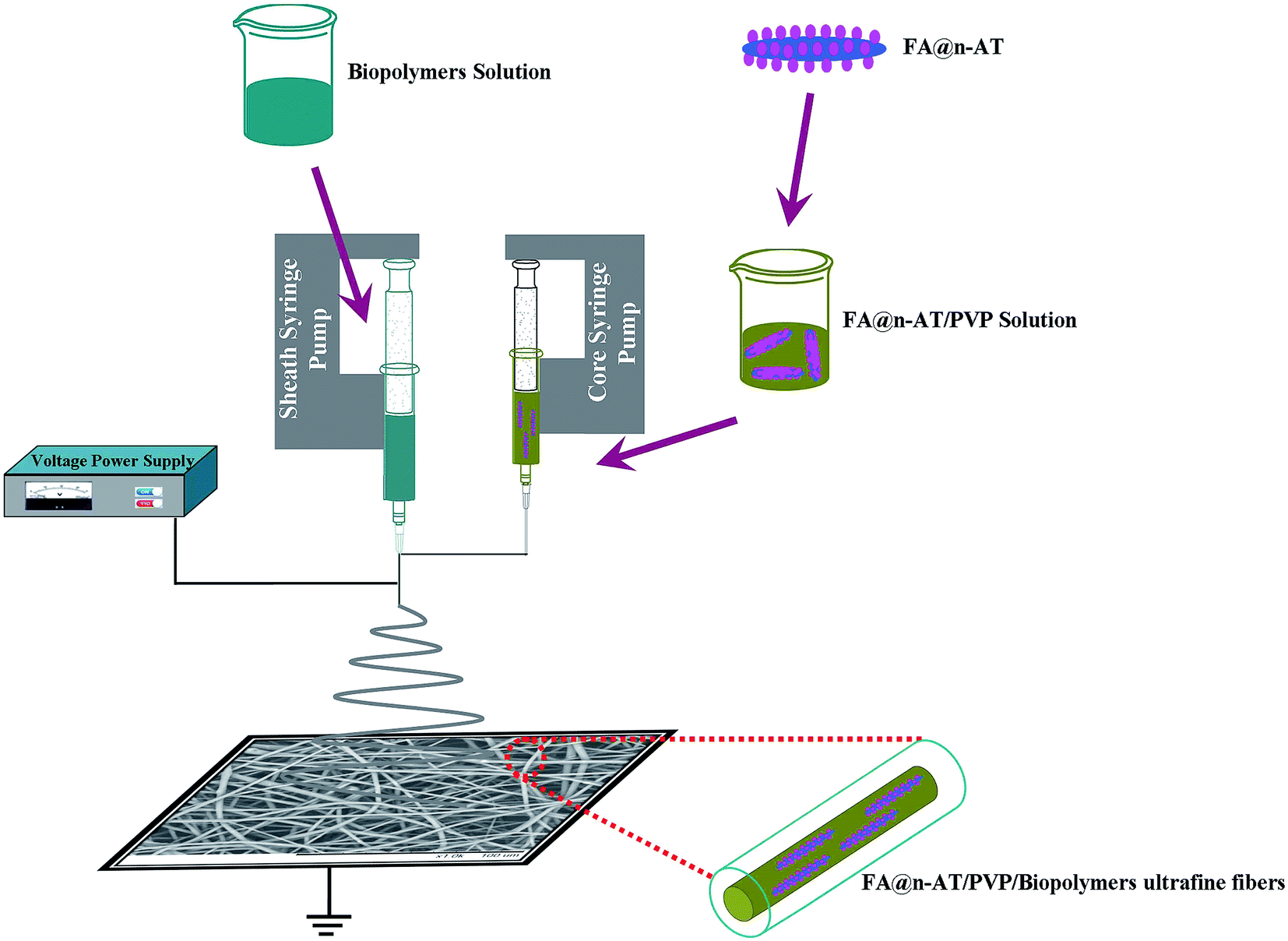 | ||
| Fig. 1 Schematic of the fabrication process of FA@n-AT/PVP/biopolymers coaxial electrospun ultrafine fibers. | ||
2. Materials and methods
2.1 Materials
Poly(lactic-co-glycolic acid) (PLGA, Mw = 100![[thin space (1/6-em)]](https://www.rsc.org/images/entities/char_2009.gif) 000 g mol−1) with a L-lactic acid/glycolic acid ratio of 50:50, poly(L-lactide-co-caprolactone) (PLCL, Mw = 80000 g mol−1) with a L-lactic acid/ε-caprolactone ratio of 50:50, poly(L-lactic acid) (PLA, Mn = 500000 g mol−1) and poly(ε-caprolactone) (PCL, Mn = 90000 g mol−1) were purchased from Jinan Daigang Biotechnology Co., Ltd. (Jinan, China). Flurbiprofen axetil (FA, purity > 99%) and FITC-FA were obtained from Shanghai Xinya Pharmaceutical Co., Ltd. (Shanghai, China). Polyvinylpyrrolidone (PVP, K30) and nano-attapulgite (n-AT, 4000 mesh) were purchased from Shanghai Zhanyun Chemical Co., Ltd. (Shanghai, China) and Mingguang Jianxi Dongfeng Mine Products Factory (Chuzhou, China). 1,1,1,3,3,3-Hexafluoro-2-propanol (HFIP) was acquired from Shanghai Darui Fine Chemical Co., Ltd. (Shanghai, China). Ethanol absolute (EtOH) and N,N-dimethylformamide (DMF) were purchased from Shanghai Lingfeng Chemical Reagent Co., Ltd. (Shanghai, China). Dulbecco's Modified Eagle's Medium (DMEM), fetal bovine serum (FBS), glutaraldehyde, 3-(4,5-dimethyl-2-thiazolyl)-2,5-diphenyl-2-H-tetrazolium bromide (MTT), acridine orange, ethidium bromide and phosphate buffer saline (PBS, pH = 7.4) were purchased from Shanghai Limin Industrial Co., Ltd. (Shanghai, China). All chemicals were used as received.
000 g mol−1) with a L-lactic acid/glycolic acid ratio of 50:50, poly(L-lactide-co-caprolactone) (PLCL, Mw = 80000 g mol−1) with a L-lactic acid/ε-caprolactone ratio of 50:50, poly(L-lactic acid) (PLA, Mn = 500000 g mol−1) and poly(ε-caprolactone) (PCL, Mn = 90000 g mol−1) were purchased from Jinan Daigang Biotechnology Co., Ltd. (Jinan, China). Flurbiprofen axetil (FA, purity > 99%) and FITC-FA were obtained from Shanghai Xinya Pharmaceutical Co., Ltd. (Shanghai, China). Polyvinylpyrrolidone (PVP, K30) and nano-attapulgite (n-AT, 4000 mesh) were purchased from Shanghai Zhanyun Chemical Co., Ltd. (Shanghai, China) and Mingguang Jianxi Dongfeng Mine Products Factory (Chuzhou, China). 1,1,1,3,3,3-Hexafluoro-2-propanol (HFIP) was acquired from Shanghai Darui Fine Chemical Co., Ltd. (Shanghai, China). Ethanol absolute (EtOH) and N,N-dimethylformamide (DMF) were purchased from Shanghai Lingfeng Chemical Reagent Co., Ltd. (Shanghai, China). Dulbecco's Modified Eagle's Medium (DMEM), fetal bovine serum (FBS), glutaraldehyde, 3-(4,5-dimethyl-2-thiazolyl)-2,5-diphenyl-2-H-tetrazolium bromide (MTT), acridine orange, ethidium bromide and phosphate buffer saline (PBS, pH = 7.4) were purchased from Shanghai Limin Industrial Co., Ltd. (Shanghai, China). All chemicals were used as received.
2.2 Preparation of FA-loaded AT nanorods
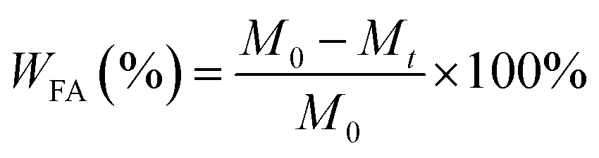
First, FA was dissolved in EtOH/Milli-Q water (v/v = 1:2) to obtain mixed solutions with different FA concentrations (0.5, 1.0, 2.0, and 4.0 mg mL−1) at room temperature. Then, n-AT was dispersed in Milli-Q water with different concentrations (1.0, 2.0, 3.0, and 4.0 mg mL−1) to obtain a batch of n-AT suspensions. Then, the FA/n-AT mixture was vigorously stirred for 24 h at room temperature to form FA-loaded n-AT (FA@n-AT). The formed FA@n-AT nanorods were separated by centrifugation (5000 rpm, 10 min) and washed with milli-Q water three times to remove the excess free FA non-adsorbed onto the n-AT surface. The FA concentration in the supernatant was analyzed using a Lambda 25 UV-vis spectrophotometer (Perkin Elmer, USA) at 246 nm using a standard FA concentration–absorbance calibration curve at the same wavelength. Finally, the FA/n-AT nanorods were obtained by lyophilization and the FA loading efficiency was calculated using the following equation:13,14
 | (1) |
2.3 Fabrication of ultrafine fibers with core–sheath structure
Biopolymers (PLGA, PLCL, PLA, and PCL) were dissolved in HFIP at the optimized concentration of 20%, 10%, 20% and 20% (w/v, biopolymers/HFIP), a as sheath layer solution, respectively. A mixture of EtOH and DMF (volume ratio 2:1) was used as the solvent to dissolve PVP and FA@n-AT powder at a concentration of 20% (w/v, the quality ratio of FA and PVP is 1:9) as the core layer solution. The sheath layer solution and core layer solution were stirred for more than 8 h and ultrasonicated about 5 min before coaxial electrospinning. FA/PVP/PLCL core–sheath nanofibers and FA/PLGA blend nanofibers were prepared according to the protocol reported in our previous studies11,12 with a commercial electrospinning instrument (SS-2533H Electrospinning Equipment, Beijing Ucalery Technology Co., Ltd., Beijing, China) using a stainless steel coaxial needle and stainless steel single-layer needle, respectively.
The applied voltage and the distance between the tip of the spinneret and the collector were maintained at 12 kV and 15 cm, respectively. The sheath flow rate was set to 1.0 mL h−1 while the core flow rate varied from 0.3 mL h−1. All the electrospinning processes were carried out at around 25 °C and 50% relative humidity. The collected ultrafine fibrous mats were finally dried under vacuum for at least 48 hours to remove residual solvent before further use.
2.4 Characterization
The morphology and structure of FA@n-AT incorporated within coaxial electrospun ultrafine fibers mats were investigated using scanning electron microscopy (SEM) (JEOL, JSM-5600, Japan). The image analysis software (Image-J, National Institutes of Health, USA) was applied to analyze the average fiber diameter (n = 100) under lower magnification (1000×). The contact angle was measured three times for each sample using a contact angle instrument (OCA40, Dataphysics, Germany) when the droplet was stable. Wide-angle X-ray diffraction (WAXD) curves were obtained on a D/max-2550 PC X-ray diffractometer (Rigaku Co., Tokyo, Japan) within the scanning region of 2θ (5–80°), with Cu Kα radiation (l = 1.5418 Å) at 40 kV and 40 mA.The FA/PVP/PLCL core–sheath nanofibers and FA@n-AT/PVP/PLCL core–sheath ultrafine fibers were observed using transmission electron microscopy (TEM) (JEOL, JEM-2100, Japan). The samples for TEM observation were prepared by putting carbon-coated copper grids on the collector to directly deposit a very thin layer of electrospun fibers. Then, the copper grids containing the fibers without staining was used to for TEM imaging by passing a beam of electrons through them.
2.5 In vitro drug release
A certain amount of FA/biopolymers blend nanofibers mats, FA/PVP/biopolymers core–sheath nanofibers mats and FA@n-AT/PVP/biopolymers core–sheath ultrafine fibers mats were weighed to ensure that the FA in the mats had a similar weight with the FA in FA@n-AT. All the samples for release experiments were added to different conical flasks containing 30 mL phosphate buffer saline (PBS, pH = 7.4). Then, the samples in PBS in different conical flasks were incubated in a vapor-bathing constant temperature vibrator at 37 °C with a vibrating speed of 100 rpm. This experiment was carried out in triplicate. At scheduled time intervals, 3 mL of sample was taken and fresh PBS medium of identical volume was added to maintain vapor-bathing constant temperature vibrator conditions. The mass of FA released at time, t, Mt, as well as the total drug amount (Mtot) were determined on a 752N UV-vis spectrophotometer (Jingke Industrial Co., Ltd, Shanghai, China) at 254 nm, in PBS and this experiment was carried out in triplicate.The percentage of accumulated release can be calculated using the following equation:
 | (2) |
2.6 Cell culture and cytocompatibility evaluation
The cytocompatibility of PLGA nanofibers, FA/PLGA nanofibers, PLCL nanofibers, FA/PLCL nanofibers, FA/PVP/PLGA core–sheath nanofibers, FA/PVP/PLCL core–sheath nanofibers, FA@n-AT/PVP/PLGA core–sheath ultrafine fibers, and FA@n-AT/PVP/PLCL core–sheath ultrafine fibers were evaluated using a diameter of 1.4 cm through the MTT cell viability assay. Mouse fibroblasts (L929) cells were cultured in a humidified incubator with 5% CO2 at 37 °C using DMEM containing 10% FBS, 100 U mL−1 penicillin, and 100 mg mL−1 streptomycin. Then, these mats were fixed in 24-well plates with stainless steel rings and sterilized with 75% alcohol for 2 h. Subsequently, all the wells with samples were washed 3 times with PBS solution to remove the residual alcohol. Finally, 1 mL of complete DMEM was added to individual wells to incubate at 37 °C overnight. L929 cells were seeded at a density of 1.0 × 10⁴ cells per well for the MTT assay. For comparison, cover slips without nanofibers were used as controls.Cell proliferation was evaluated on day 1, 3, 5, and 7. All the experiments were performed in triplicate. The absorbance from the samples containing the membranes only was corrected to modulate the final optical density (OD) values. In brief, at the end of each time point, the cells were washed with PBS and an MTT solution (40 μL) was added to each well, followed by incubation for another 4 h. Then, 400 μL DMSO was added to each well to dissolve the purple MTT formazan crystal for 15 min and 100 μL of the dissolved formazan solution of each sample was transferred into separate wells of a 96-well plate to test the OD value at 492 nm using a microplate reader (MK3, Thermo, USA). The mean and standard deviation from triplicate wells for each sample are reported.
2.7 Statistical analysis
The one-way ANOVA statistical method was used to evaluate the significance of the experimental data. A value of 0.05 was selected as the significance level and the data are indicated with (*) for p < 0.05, (**) for p < 0.01, and (***) for p < 0.001.3. Results and discussion
3.1 Loading of FA onto the n-AT surfaces
Different from our previous study related to the use of the FA/PVP/PLGA core–sheath nanofibers for drug encapsulation, the nanoporous space of n-AT was used to encapsulate the model drug FA. n-AT have a three-dimensional structure with six octahedral magnesium ions sandwiched between two layers of four tetrahedral silicon atoms, and the interlayer space of n-AT has been proven to be used as a reservoir for drug encapsulation.The loading percentage of FA onto n-AT was optimized by regulating the respective concentration of FA and n-AT under the same experimental conditions. The profile of the FA loading percentage as a function of FA concentration under different n-AT concentrations is shown in Fig. 2. It is clear that the FA loading percentage increases with the increase of FA concentration and as the n-AT concentration increases, the FA loading percentage increases quickly then increases slowly. When the concentration of n-AT is 4 mg mL−1, the FA loading percentage is lower than the concentration of n-AT at the level of 3 mg mL−1. This could be attributed to the aggregation of the n-AT at a higher concentration, which leads to a relatively limited n-AT surface area to be accessed by the FA molecules. Therefore, 2 mg mL−1 is considered to be the saturation concentration of FA when the n-AT concentration is 3 mg mL−1 and the optimized FA loading percentage is 89.5%.
 | ||
| Fig. 2 FA loading efficiency as a function of FA concentration under different n-AT concentrations. | ||
3.2 Fabrication of FA@n-AT/PVP/biopolymers core–sheath ultrafine fibrous mats
TEM and fluorescence microscopy were used to confirm the incorporation of FA@n-AT into the ultrafine fibers (Fig. 3). FA@n-AT within the core–sheath ultrafine fibers with a uniform distribution can be clearly observed (Fig. 3(b)) similar to the FA/PVP/PLCL core–sheath nanofibers (Fig. 3(a)), while only a few small green fluorescence spots caused by the partial aggregation of FA were present in the image of the FA/PVP/PLCL core–sheath nanofibers. The TEM image in Fig. 3(b) indicates that FA@n-AT was successfully embedded in the core of the core–sheath ultrafine fibers. The green fluorescence illustrates that FA could be homogeneously encapsulated within the core of core–sheath fibers (Fig. 3(c) and (d)). This result further reveals that the FA@n-AT can be embedded in the core of FA@n-AT/PVP/PLCL core–sheath ultrafine fibers with uniform distribution. | ||
| Fig. 3 TEM images of (a) FA/PVP/PLCL core–sheath nanofiber and (b) FA@n-AT/PVP/PLCL ultrafine fiber. Fluorescence of (c) FA/PVP/PLCL core–sheath nanofibers and (d) FA@n-AT/PVP/PLCL core–sheath ultrafine fibers. | ||
The XRD patterns of pristine n-AT powder and after FA was loaded onto n-AT surfaces are shown in Fig. 4. It can be observed that most of the indexed diffraction peaks of n-AT are similar to those of n-AT after the loading of FA. The intensity of some of the typical n-AT diffraction peaks (e.g., at 26.8° and at 35.5°) decreased after loading of FA onto n-AT, possibly due to the surface adsorption of the FA molecules. The peaks related to the FA drug (Fig. 4(a)–(c)) do not appear in the XRD pattern of FA@n-AT, which is likely due to the fact that the loaded amount of FA drug is too low to be detected by XRD technology.
 | ||
| Fig. 4 TEM images n-AT nanorod powder before (a) and after (b) loading of FA and X-ray diffraction patterns (c) of n-AT nanorod powder, FA@n-AT nanorod powder and pure FA. | ||
The surface morphology and diameter distribution of FA@n-AT/PVP/PLA core–sheath fibers, FA@n-AT/PVP/PCL core–sheath fibers, FA@n-AT/PVP/PLGA core–sheath fibers and FA@n-AT/PVP/PLCL core–sheath fibers were observed via SEM (Fig. 5). It can be observed that the surface of these core–sheath ultrafine fibers was smooth and beadless, with no nanorods being observed on the surface these fibers (Fig. 5). With the easy coaxial electrospinnability of PVP and biopolymers, the incorporation of FA@n-AT does not seem to significantly alter the uniform and smooth fibrous morphology of the biopolymers fibers. The average diameters of the FA@n-AT/PVP/PLA core–sheath fibers, FA@n-AT/PVP/PCL core–sheath fibers, FA@n-AT/PVP/PLGA core–sheath fibers and FA@n-AT/PVP/PLCL core–sheath fibers were 2081, 3088, 2393 and 1349 nm, respectively (Fig. 5). Compared with the FA/biopolymers blend nanofibers (diameter approximately 370 ± 40 nm) and FA/PVP/biopolymers core–sheath nanofibers (diameter approximately 710 ± 30 nm) in our previous studies,11,12 the diameter increase of the FA@n-AT/PVP/biopolymers fibers are presumably due to the addition of PVP and FA@n-AT, which was caused by n-AT and the biopolymers types and this enhanced the viscosity of the composite solution. Different diameter distributions may lead to different drug release models.13,15,16 This may due to the effect of the surface morphology, which suggests that the narrow diameter of fibers increase the surface area of the nanofibers and allows easy penetration of water into and easy diffusion of biopolymers out of the composite nanofiber core.
 | ||
| Fig. 5 SEM images, diameter distribution histograms and water contact angle of (a) FA@n-AT/PVP/PLA core–sheath ultrafine fibers, (b) FA@n-AT/PVP/PCL core–sheath ultrafine fibers, (c) FA@n-AT/PVP/PLGA core–sheath ultrafine fibers and (d) FA@n-AT/PVP/PLCL core–sheath ultrafine fibers. | ||
Surface hydrophilicity plays an important role in the practical application of electrospun nanofibers.14,17,18 The data from the water contact angle measurements (Fig. 5) implies a hydrophobic surface characteristic of the FA@n-AT/PVP/PLCL fibrous mats, which showed an average contact angle of 119°. It can be observed that the water contact angle of the FA@n-AT/PVP/PLA fibrous mats, FA@n-AT/PVP/PCL fibrous mats, FA@n-AT/PVP/PLGA fibrous mats were 35°, 94°, and 12° (Fig. 5), respectively, which was obviously less than that of the pure biopolymers, as reported in Yang's research,6 because of the presence of PVP. Thus, the hydrophilicity of nanofibrous mats can be enhanced by the addition of PVP.
3.3 Release of FA from FA@n-AT/PVP/PLGA core–sheath ultrafine fibrous mats
The in vitro drug release profiles of the FA@n-AT/PVP/PLGA core–sheath ultrafine fibers were investigated by exposing the fibrous mats in PBS solution (pH = 7.4) at 37 °C.19 The FA release profile was compared with those from FA/PLGA blend nanofibers and FA/PVP/PLGA core–sheath nanofibers with a similar drug content (Fig. 6). It is clear that the FA/PLGA blend nanofibers exhibit an obvious initial burst release. FA in the FA/PLGA blend nanofibers has a burst release profile and about 70% of the loading FA can be released from the PLGA matrix within 24 h. Due to the fact that the physical hybrid method only caused FA molecules to adsorb on the PLGA molecular chain and this interaction was very weak, FA molecules were very easily separated from the PLGA matrix in the process of drug release. For the FA/PVP/PLGA core–sheath nanofibers system, the drug release rate became slower than the FA/PLGA blend nanofibers system. This is because the release of drugs from a polymeric matrix undergoes several steps: water from the medium diffuses in through polymeric networks and dissolves the drug molecules, followed by diffusion out of the matrix and into the medium. By contrast, the FA release from FA@n-AT/PVP/PLGA core–sheath ultrafine fibers needs to go through three processes: the FA dissociation first from n-AT to PVP and then from PVP to biopolymers fiber matrix; finally, from biopolymers fiber matrix to the release medium. Therefore, about 25% of the FA was released in the initial 24 h and the release was very slow in the following 180 hours. Thus, when the release profile tended towards stability after 180 hours, the cumulative release rate was approximately 60%. | ||
| Fig. 6 In vitro release of FA from FA@n-AT nanorods, FA/PLGA blend nanofibers, FA/PVP/PLGA core–sheath nanofibers and FA@n-AT/PVP/PLGA core–sheath ultrafine fibers with a similar mass of FA. | ||
3.4 Cytocompatibility assay
For further biomedical applications, it is important to ensure the biocompatibility of developed fibrous materials.20 The cell proliferation measured using the MTT assay of mouse fibroblasts (L929) cells cultured on different electrospun fibrous mats within 7 days is shown in Fig. 7. At day 1, 3, 5 and 7, cell proliferation on all membranes was faster compared with that on the cover slips (*p < 0.05). At day 1, there was no obvious difference among these mats. However, at day 3, the FA@n-AT/PVP/PLGA core–sheath ultrafine fibrous mat and FA@n-AT/PVP/PLGA core–sheath ultrafine fibers mat were the most excellent and showed significant difference compared with the other six mats (*p < 0.05). When cultured after 5 days, the amount of cells greatly increases, which indicates that all the mats enhance cell growth and proliferation. Moreover, from the seventh day, the cell amount does not have a more significant increase than that from the fifth day. Furthermore, the FA@n-AT/PVP/biopolymers core–sheath ultrafine fibrous mats with the addition of n-AT were statistically significant (*p < 0.05) in comparison to the biopolymers nanofibrous mats, FA/biopolymers blend nanofibrous mats, and FA/PVP/biopolymers core–sheath nanofibrous mats possibly because the FA@n-AT/PVP/biopolymers core–sheath ultrafine fibrous mats don't shrink during culture. | ||
| Fig. 7 Proliferation of mouse fibroblasts seeded on cover slips, biopolymers nanofibrous mats, FA/biopolymers blend nanofibrous mats, FA/PVP/biopolymers core–sheath nanofibrous mats, and FA@n-AT/PVP/biopolymers core–sheath ultrafine fibrous mats. *p < 0.05, **p < 0.01 versus control. | ||
4. Conclusion
In summary, FA@n-AT/PVP/biopolymers core–sheath ultrafine fibers with a smooth surface morphology and improved FA release profile were successfully fabricated via coaxial electrospinning. After the addition of PVP and FA@n-AT, the average diameter of the resultant composite fibers increased and the water contact angle was slightly enhanced. The combination of three pathways for the FA dissociation: first, from n-AT to PVP and then from PVP to biopolymers fiber matrix, and finally from biopolymers fiber matrix to the release medium in a sustained release manner is proven to be an efficient strategy to slow down the release rate of FA. Moreover, the results show that the FA@n-AT/PVP/biopolymers core–sheath ultrafine fibrous mats tend to promote mouse fibroblast proliferation when compared with biopolymers nanofibrous mats, FA/biopolymers blend nanofibrous mats, and FA/PVP/biopolymers core–sheath nanofibrous mats. This is important for biomedical applications that require a drug to maintain long term analgesic efficacy.Acknowledgements
The authors sincerely appreciate the supports of the “National Nature Science Foundation (31470941, 31271035)”, “Ph.D Programs Foundation of Ministry of Education of China (20130075110005)”. “Science and Technology Commission of Shanghai Municipality (15JC1490100, 15441905100)”, “Yantai Double Hundred Talent Plan”, and light of textile project (J201404), the authors would like to extend their sincere appreciation to the Deanship of Scientific Research at King Saud University for its funding of this research through the research group project (No. RGP-201).References
- O. Ohmukai, Adv. Drug Delivery Rev., 1996, 20, 203–207 CrossRef CAS.
- K. Yamashita, M. Fukusaki, Y. Ando, A. Fujinaga, T. Tanabe, Y. Terao and K. Sumikawa, J. Anesth., 2006, 20, 92–95 CrossRef PubMed.
- J. Q. Shen, L. Gan, C. L. Zhu, X. X. Zhang, Y. Dong, M. Jiang, J. B. Zhu and Y. Gan, Int. J. Pharm., 2011, 412, 115–122 CrossRef CAS PubMed.
- L. L. Zhang, J. Zhu, L. Xu, X. L. Zhang, H. Y. Wang, Z. H. Luo, Y. M. Zhao, Y. Yu, Y. Zhang and H. W. Shi, Med. Sci., 2014, 6, 995–1002 Search PubMed.
- X. Lin, R. Q. Zhang, J. C. Xing, X. C. Gao, P. Chang and W. Z. Li, Int. J. Clin. Exp. Med., 2014, 7, 4887–4896 Search PubMed.
- C. Y. Yang, T. H. Zhu, J. H. Wang, S. H. Chen and W. Y. Li, RSC Adv., 2015, 5, 69423–69429 RSC.
- H. Xu, H. C. Yang, S. Xue, J. Pan, Q. T. Ni and F. H. Gong, J. Appl. Polym. Sci., 2015, 132, 42762 Search PubMed.
- J. P. Zhang, Q. Wang and A. Q. Wang, Carbohydr. Polym., 2007, 68, 367–374 CrossRef CAS.
- Q. L. Yuan, W. B. Lu and Y. K. Pan, Polym. Degrad. Stab., 2010, 95, 1581–1587 CrossRef CAS.
- Z. Wang, Y. L. Zhao, Y. Luo, S. G. Wang, M. W. Shen, H. Tomás, M. F. Zhu and X. Y. Shi, RSC Adv., 2015, 5, 2383–2391 RSC.
- T. H. Zhu, S. H. Chen, W. Y. Li, J. Z. Lou and J. H. Wang, J. Appl. Polym. Sci., 2015, 132, 41982 Search PubMed.
- T. H. Zhu, C. Y. Yang, S. H. Chen, W. Y. Li, J. Z. Lou and J. H. Wang, Mater. Lett., 2015, 150, 52–54 CrossRef CAS.
- S. G. Wang, F. Y. Zheng, Y. P. Huang, Y. T. Fang, M. W. Shen, M. F. Zhu and X. Y. Shi, ACS Appl. Mater. Interfaces, 2012, 4, 6393–6401 CAS.
- F. Y. Zheng, S. G. Wang, S. H. Wen, M. W. Shen, M. F. Zhu and X. Y. Shi, Biomaterials, 2013, 34, 1402–1412 CrossRef CAS PubMed.
- T. T. T. Nguyen, C. Ghosh, S.-G. Hwang, N. Chanunpanich and J. S. Park, Int. J. Pharm., 2012, 439, 296–306 CrossRef CAS PubMed.
- M. M. Castillo-Ortega, A. G. Montaño-Figueroa, D. E. Rodríguez-Félix, G. T. Munive and P. J. Herrera-Franco, Mater. Lett., 2012, 76, 250–254 CrossRef CAS.
- Y. Z. Zhang, X. Wang, Y. Feng, J. Li, C. T. Lim and S. Ramakrishna, Biomacromolecules, 2006, 7, 1049–1057 CrossRef CAS PubMed.
- S. Fredenberg, M. Wahlgren, M. Reslow and A. Axelsson, Int. J. Pharm., 2011, 415, 34–52 CrossRef CAS PubMed.
- R. L. Qi, R. Guo, F. Y. Zheng, H. Liu, J. Y. Yu and X. Y. Shi, Colloids Surf., B, 2013, 110, 148–155 CrossRef CAS PubMed.
- F. J. Liu, S. Y. Wang and X. Y. Shi, Proceedings of 2009 International Conference on Advanced Fibers and Polymer Materials, Shanghai, China, 21–24 October 2009, pp. 517–520 Search PubMed.
| This journal is © The Royal Society of Chemistry 2016 |