DOI:
10.1039/C6RA07849D
(Paper)
RSC Adv., 2016,
6, 56819-56826
Preparation and evaluation of Nafion/SnO2 nanocomposite for improving the chemical durability of proton exchange membranes in fuel cells
Received
26th March 2016
, Accepted 6th June 2016
First published on 7th June 2016
Abstract
Durability of proton exchange membrane (PEM) fuel cells is one of the most crucial issues for fuel cell commercialization. On the other hand, chemical degradation of membranes is a major factor limiting the lifetime of PEM fuel cells. In this regard, a Nafion/SnO2 nanocomposite membrane was prepared to improve the chemical durability of the membrane in fuel cells. The water uptake, ion exchange capacity, proton conductivity, thermal and mechanical properties of membranes were investigated. Fenton's test was used as an ex situ accelerated test to evaluate the stability of membranes. It was found that the fluoride release and weight loss in the Nafion/SnO2 nanocomposite membrane are less than those in the pure Nafion membrane, which demonstrates the improved chemical durability of the Nafion/SnO2 nanocomposite membrane. ATR-FTIR spectra and SEM surface images of membranes support these findings. Thus the results of this study indicate that incorporation of SnO2 nanoparticles in the Nafion membrane can improve the chemical durability, which is important for extending the lifetime of PEM fuel cells.
1. Introduction
Due to growing concerns regarding the depletion of petroleum-based energy resources and climate change, fuel cell technologies have attracted attention as a next generation energy system in the energy industry.1 In particular, proton exchange membrane (PEM) fuel cells are expected to be used as one of the most promising candidates for clean energy technologies.2,3 Enhancing the durability of PEM fuel cells is one of the most crucial issues for commercial applications.4–6 Perfluorinated sulfonic acid (PFSA) membranes, especially Nafion, are the most widely used electrolyte materials in typical PEM fuel cells.7 Chemical degradation of membranes is a major factor limiting the lifetime of PEM fuel cells.8–10 It is generally accepted that the cause of the membrane degradation is the creation and presence of free radicals which chemically attack the polymer membrane.11,12 These free radicals are produced either from the decomposition of hydrogen peroxide, which forms when oxygen is partially reduced, or directly from the reaction of hydrogen and oxygen on the surface of the platinum catalyst because of gas crossover through the membrane. Radical attack of the membrane leads to a decrease in ion exchange capacity, proton conductivity, or membrane thickness.13–17
In recent years, much attention has been devoted to mitigate the membrane degradation and several approaches have been proposed to address this problem. For instance, reducing the gas crossover by using a thicker membrane,18 or reducing the hydrogen peroxide concentration by using hydrogen peroxide decomposition catalysts within the electrolyte and electrode.19 Also, another approach is to include inorganic nanoparticles such as CeO2, MnO2 or ZrO2 into the polymer membrane to decompose the aggressive radicals during operation.20–22 The performance of these radical scavengers is based on the faster reaction rate they have with radicals than the reaction rate radicals have with the membrane.23
As an important semiconductor with high chemical stability and excellent optical and electrical properties,24 SnO2 has been investigated in various areas, such as gas sensors,25 photocatalysts,26 solar cells27 and lithium-ion batteries.28 In addition, SnO2 has been employed as filler in composite polymer electrolyte membranes to prevent methanol crossover29 and to improve mechanical properties.30 Recently, Andersen et al.31 introduced the use of SnO2 nanoparticles in the electrode structure of PEM fuel cell. Their results show that SnO2 nanoparticles can act as a radical scavenger. In analogy to CeO2,32 a possible antioxidant mechanism for SnO2 consists of the following steps:31
| | |
Sn2+ + 2HO˙ + 2H+ → Sn4+ + 2H2O
| (1) |
| | |
Sn4+ + 2H2O2 → Sn2+ + 2HOO˙ + 2H+
| (2) |
| | |
Sn4+ + 2HOO˙ → Sn2+ + 2O2 + 2H+
| (3) |
| | |
Sn4+ + H2 → Sn2+ + 2H+
| (4) |
| | |
2Sn4+ + 2H2O → 2Sn2+ + 4H+ + O2
| (5) |
To our knowledge, SnO2 has never been investigated as a radical scavenger in composite polymer electrolyte membranes to mitigate the membrane degradation. Therefore, the aim of this paper is to present the influence of SnO2 nanoparticles on the chemical stability of Nafion membrane.
2. Experimental
2.1. Synthesis of SnO2 nanoparticles
The SnO2 nanoparticles were synthesized according to our recent report.33 Briefly, 0.5 g of SnCl4·5H2O was dissolved in 40 ml of distilled water. Then, 0.2 ml of ethylenediamine and 0.4 ml hydrazine hydrate were added drop wise to the solution under stirring. The resulting solution was transferred into a stainless Teflon-lined 70 ml capacity autoclave. The autoclave was sealed and maintained at 200 °C for 5 h, then cooled naturally to room temperature. The obtained precipitate was collected by centrifugation, washed with distilled water and ethanol several times, and dried at 70 °C for 3 h. Finally, it was calcined at 400 °C for 2 h.
2.2. Preparation of Nafion/SnO2 nanocomposite membranes
The nanocomposite membranes were prepared by the solution-casting method. The Nafion perfluorinated resin solution (equivalent weight (EW) = 1100, 5 wt% in lower aliphatic alcohols and water, contains 15–20% water) was supplied by Aldrich. Typically, the commercial Nafion solution was concentrated at 80 °C so as to reduce the volume by 90%. The proper amount of N,N-dimethylformamide (DMF) was added to the remaining solution, and the volume was reduced again. The procedure was repeated several times in order to ensure the complete removal of water and alcohols. The Nafion/DMF solution, and 0, 2, 4 or 8 wt%, SnO2 nanoparticles (with respect to Nafion content), were mixed ultrasonically to form the slurry. Then the slurry was cast on a flat glass plate and dried at 80 °C for 24 h. Subsequently, the membranes were annealed at 120 °C for 4 h in an oven. Finally, the composite membranes were stirred in distilled water at 80 °C for 2 h, in 2 M HCl for 2 h at 80 °C and for 36 h at room temperature. The samples were then washed several times with distilled water.
2.3. Ion exchange capacity (IEC) and water uptake
The membrane was immersed in 20 ml of an aqueous 2 M NaCl solution overnight, to allow the replacement of protons with Na+ ions. Protons released from the membrane were titrated by 0.01 M NaOH solution to pH = 7.
The IEC was calculated using the following equation:
| |
 | (6) |
where
CNaOH = 0.01 M,
VNaOH is the volume of the NaOH solution used for titration and
mdry is the initial dry weight of the membrane in acid form.
The water uptake of membranes was determined by the following equation:
| |
 | (7) |
where
mwet and
mdry are the weights of wet and dry membranes, respectively. To determine the wet weight of the membranes, they were placed in distilled water for 24 h at room temperature and then weighed after blotting the surface water. To determine the dry weight of the membranes, they were placed in an oven at 80 °C for 24 h, cooled to room temperature under vacuum and then weighted.
The number of water molecules per sulfonic acid groups (λ) can be expressed by the following equation:
| |
 | (8) |
where
MW is the molecular weight of water and IEC is the ion exchange capacity of the membrane.
2.4. Proton conductivity
To investigate the proton conducting performance of the membranes, the through-plane proton conductivities of the membranes were measured using impedance spectroscopy with an AutoLab (PGSTAT 30) at AC amplitude of 10 mV. Membranes were sandwiched between two stainless steel disks, separated by a Teflon holder, homemade cell configuration is similar to the one reported by Müller et al.34 The impedance of the fully humidified membranes was measured at 25 °C in the frequency range of 1 MHz to 1 kHz. Proton conductivity of the membranes was calculated using the following:| |
 | (9) |
where σ is the proton conductivity (S cm−1), L is the thickness (cm) of the membrane, A is the electrode surface area (cm2), and R is the membrane resistance (Ω) calculated from the Nyquist plot.
2.5. Thermal and mechanical properties
Thermogravimetric analyses were performed using a LINSEIS L81A1750 (Germany). The pure Nafion and Nafion/SnO2 4 wt% nanocomposite membranes were examined in nitrogen atmosphere from 50 to 750 °C with a heating rate of 10 °C min−1.
Tensile strength measurements were carried out at room temperature using a MTS tensile tester Model 10/M with 5 mm min−1 strain rate. Membrane samples with an area of 50 × 10 mm2 were cut and used for mechanical studies.
2.6. Membrane chemical durability test
Two different methods were used as ex situ accelerated test for predicting the stability of membranes. The first method was the Fenton's test,35 where the membrane samples were immersed in Fenton's solution (30 wt% H2O2 solution and 20 ppm Fe2+) at 80 °C in the dark. The Fenton's reagents were replaced every 3 h to keep a constant H2O2 concentration. All the replaced solution was collected for the further analysis. In the alternative method, similar to the method reported by Weissbach et al.20 the membranes were cast from Nafion solutions containing FeSO4 (the Fe2+ content of the membranes was ∼10![[thin space (1/6-em)]](https://www.rsc.org/images/entities/char_2009.gif) 000 ppm) and subsequently exposed to only aqueous H2O2 solution at 80 °C in the dark. The H2O2 solution was replaced every 3 h and analyzed for fluoride content. The second method will be referred to as the co-casting method.
000 ppm) and subsequently exposed to only aqueous H2O2 solution at 80 °C in the dark. The H2O2 solution was replaced every 3 h and analyzed for fluoride content. The second method will be referred to as the co-casting method.
2.7. Fluoride release and weight loss
The amount of fluoride released into the Fenton's solution was determined with a fluoride ion meter. Total ionic strength adjustment buffer (TISAB) was added to all collected solutions to provide a constant ionic strength. The fluoride release of the membranes (mmol g−1) was expressed by the following equation:| |
 | (10) |
where [F−] is the measured fluoride concentration (ppm), Vsolution is the volume of the Fenton's solution (ml), MF is the is the molar mass of fluorine (19.0 g mol−1) and mdry is the initial dry weight of the membrane (mg).
The weight loss of membranes was determined by the following equation:
| |
 | (11) |
where
mi and
mf are the dry weights of the membranes before and after treatment in Fenton's solution, respectively.
2.8. Attenuated total reflection Fourier transform infrared (ATR-FTIR) spectroscopy
The ATR-FTIR spectra were measured with a Tensor 27 (Bruker) spectrometer with a ZnSe ATR crystal, at the resolution of 2 cm−1 between 600 and 4000 cm−1. The samples were pressed onto the ATR crystal with equal pressure to avoid differences in the size or shape.
2.9. Electron microscopy
Energy dispersive X-ray (EDX) spectrum and scanning electron micrographs (SEM) were obtained using a field-emission scanning electron microscopy (MIRA3 FEG-SEM, Tescan Brno, Czech Republic). Cross-section of membrane was prepared by freeze fracture in liquid nitrogen.
Transmission electron microscope (TEM) images were obtained on a Philips EM208 transmission electron microscope with an accelerating voltage of 100 kV. The membrane was embedded into epoxy resin and ultramicrotomed into thin sections, which were transferred onto a carbon film coated copper grid.
3. Results and discussion
3.1. Properties of membranes
Nafion nanocomposite membranes containing 2, 4 and 8 wt% SnO2 nanoparticles were prepared and their properties compared to pure Nafion membrane (additive content, 0 wt%). As can be seen from Table 1, the water uptake firstly increased and reached a maximum 23.01 wt% at 2 wt% SnO2, and then showed a decreasing trend with further increasing SnO2 content. The same trend was also observed for the number of water molecules per sulfonic acid group (λ). This result is consistent with previous reports that at higher contents, SnO2 particles in the membrane seem to displace water and restrict compensational dimensional expansion to accommodate more water.30
Table 1 Water uptake and water molecules per sulfonic acid group (λ) of the membranes at 25 °C
| SnO2 content [wt%] |
Water uptake [wt%] |
λ |
| 0 |
20.63 |
12.79 |
| 2 |
23.01 |
14.64 |
| 4 |
21.34 |
13.87 |
| 8 |
18.59 |
12.39 |
The IEC values indicate the density of exchangeable acidic groups in the membranes. Fig. 1a displays the IEC value of the composite membranes compared to pure Nafion membrane (0.896 mmol g−1). As can be seen, the IEC values of the composite membranes are lower than those of the pure Nafion membrane and decreased with increasing SnO2 content. For instance, the addition of 8 wt% SnO2 lowers the IEC value to 0.802 mmol g−1. This change is due to decrease of sulfonic acid groups in the composite membrane.36
 |
| | Fig. 1 (a) Ion exchange capacity (IEC) and proton conductivity (σ) of membranes, and (b) Nyquist plots of membranes (the inset represents the equivalent circuit model used to fit the experimental data). | |
Membrane proton conductivity (σ) is one of the crucial properties affecting PEM fuel cells performance.37,38 In this regards, the proton conductivity of membranes was measured using AC impedance method at room temperature. Fig. 1b shows the Nyquist plot and equivalent circuit model employed to fit the impedance data. As can be seen from Fig. 1a, the proton conductivity of the composite membranes is lower than those of the pure Nafion membrane. With increasing SnO2 content, proton conductivity decreases from 18.60 mS cm−1 (pure Nafion) to 15.79, 13.98 and 8.19 mS cm−1 for 2, 4 and 8 wt% additive content, respectively. Generally, the proton transport mechanism in the Nafion-based membranes occurs by Grotthuss and Vehicular mechanisms.39–41 In the vehicular mechanism, hydronium ions diffusing through the membrane, while in the Grotthuss mechanism proton hops from one sulfonic acid group to another sulfonic group. The decrease in proton conductivity with increasing SnO2 content can be explained by blocking of sulfonic sites by SnO2 particles, which disarrange the continuity of sulfonic group clusters (Grotthuss mechanism). Also, SnO2 particles can fill the porosity channels of membranes which restrict the free diffusion of protons (Vehicular mechanism). Similar description was also reported for other Nafion-based nanocomposite membranes.42,43
The SEM images of the cross-section and the EDX mapping analysis of the Nafion/SnO2 4 wt% nanocomposite membrane are shown in Fig. 2a–c. As can be seen, the nanoparticles were homogeneously distributed throughout the cross section of membrane. A TEM micrograph of the Nafion/SnO2 4 wt% nanocomposite membrane is shown in Fig. 2d. The dark contrast in the micrograph corresponds to the SnO2 nanoparticles, while the white contrast corresponds to the polymer chains. It is evident that the nanoparticles were uniformly distributed in the membrane and the diameters of the nanoparticles were in the range of 10–20 nm.
 |
| | Fig. 2 (a) and (b) SEM images of cross-section, (c) EDX mapping analysis (red dots: Sn, yellow dots: O), and (d) TEM image of the Nafion/SnO2 4 wt% nanocomposite membrane. | |
The thermal stability of the pure Nafion and Nafion/SnO2 4 wt% nanocomposite were evaluated by TGA analysis as shown in Fig. 3. The TGA curves of the membranes show three stages of weight loss corresponding to the removal of the evaporation of absorbed water (50–150 °C), decomposition of sulfonic acid groups (265–350 °C) and decomposition of the polymer backbone (the onset at 390 °C), respectively.44,45 Pure Nafion is completely decomposed at 520 °C, whereas Nafion/SnO2 4 wt% nanocomposite decomposed completely at 550 °C. However, no improvement in thermal stability was seen at the initial state of degradation, although Nafion/SnO2 shows a retarded thermal decomposition to 550 °C.
 |
| | Fig. 3 TGA thermogram of the pure Nafion and Nafion/SnO2 4 wt% nanocomposite membranes. | |
The mechanical strength of the pure Nafion and Nafion/SnO2 4 wt% nanocomposite were evaluated by means of tensile test, and results are summarized in Table 2. The tensile strength, Young's modulus and maximum strain for Nafion membrane are 16 MPa, 178 MPa and 162%, respectively, which is in agreement with previously reported values.46 The tensile strength and maximum strain of the Nafion/SnO2 nanocomposite membrane is lower than the Nafion membrane. The incorporation of SnO2 nanoparticles increases the Young's modulus of the membrane, which is in agreement with the literature.30 Thus, the incorporation of SnO2 nanoparticles is not supposed to improve the mechanical strength of Nafion membrane.
Table 2 Mechanical properties of membranes
| Samples |
Tensile strength (MPa) |
Young's modulus (MPa) |
Maximum strain (%) |
| Nafion |
16 |
178 |
162 |
| Nafion/SnO2 4 wt% |
14 |
219 |
87 |
3.2. Chemical durability of the membranes
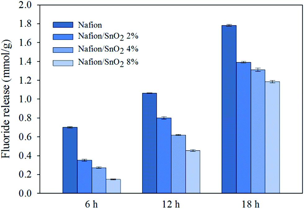
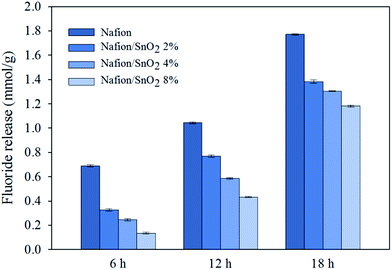
As mentioned in introduction, it has been widely recognized that the free radicals are a major source of chemical degradation of membranes. In order to investigate the membrane durability, two different methods were used as ex situ accelerated test. Fenton's reagent, leads to the production of free radicals in the solution.47 The main advantage of this test compared to in situ degradation test is the observation of membrane degradation process without interference in the Pt catalyst layer.38,48 The release of fluoride in Fenton's solution as well as the loss of membrane weight can be used to quantify the degree of degradation.48,49 Lower fluoride concentration in Fenton's solution means less C–F bond decomposition and thus lower chemical degradation of membranes. The amount of fluoride released into Fenton's solution is shown in Fig. 4. As can be seen from this figure, the addition of SnO2 nanoparticles into membranes can reduce the amount of fluoride release from membranes. The same trend was also observed for the loss of membrane weight, as shown in Fig. 5. Recently, Weissbach et al. introduced a method that incorporates a controlled quantity of iron species in the membrane and subsequently exposed to only aqueous H2O2 solution.20 For more investigation, we used the same method to evaluate the chemical stability of membranes. The amount of fluoride released into H2O2 solution is shown in Fig. 6. Comparison Fig. 5 and 6 demonstrate that the amount of fluoride released is very similar in both methods. This result is consistent with previous work of Weissbach et al. These results indicate that Nafion/SnO2 nanocomposite exhibit more chemical durability than the pure Nafion membrane. This better durability is consistent with the reported radical scavenging ability of SnO2 nanoparticles.31 From comparison with other studies, it seems that the amount of fluoride release from Nafion/SnO2 membrane is higher than that from Nafion/CeO2 membrane.20,22 However, the chemical stability of Nafion/SnO2 membrane is better than that of Nafion/ZrO2 membrane.19,20
 |
| | Fig. 4 Fluoride release as a function of reaction time (related to Fenton's method). | |
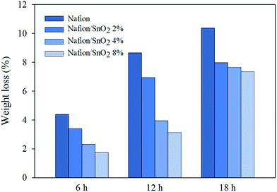 |
| | Fig. 5 Weight loss of membranes as a function of Fenton's reagent reaction time. | |
 |
| | Fig. 6 Fluoride release as a function of reaction time (related to co-casting method). | |
Fig. 7 displays the ATR-FTIR spectra of the pure Nafion and Nafion/SnO2 4 wt% nanocomposite membranes at various sampling times (related to Fenton's method). The peak at 1143 cm−1 is assigned to the C–F symmetric vibration, and the peak at 1204 cm−1 is attributed to the C–F asymmetric stretching vibration. The S–O symmetric vibration is visible at about 1063 cm−1. The peak at 978 cm−1 is assignable to the C–O–C symmetric vibrations.50,51 For various sampling times, there is no obvious change in the shapes and peak positions of the spectra, which indicated no changes in the membrane structure during degradation. As expected, the intensity of peaks decrease with increasing the immersion time; however, this decrease in the Nafion/SnO2 nanocomposite is lower than the pure Nafion.
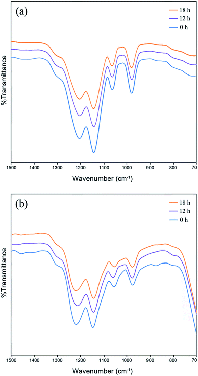 |
| | Fig. 7 ATR-FTIR spectra of (a) the pure Nafion and (b) Nafion/SnO2 4 wt% nanocomposite membranes at different Fenton's reagent reaction time. | |
Fig. 8 shows the surface morphology of the pure Nafion and Nafion/SnO2 4 wt% nanocomposite membranes at various sampling times (related to Fenton's method). It is clearly seen that for the pure Nafion, after treatment in Fenton's solution for 12 h, there are pinholes on the membrane surface. These cracks and pinholes were developed with increasing the immersion time to 18 h. These pinholes cause gas crossover and therefore lead to structural failure of the membranes. As can be seen from Fig. 8, Nafion/SnO2 4 wt% nanocomposite membranes have smooth surface after treatment in Fenton's solution. These results confirm the fact that Nafion/SnO2 nanocomposite exhibit more chemical durability than the pure Nafion membrane.
 |
| | Fig. 8 SEM images of the pure Nafion and Nafion/SnO2 4 wt% nanocomposite membranes at different Fenton's reagent reaction time. | |
Fig. 9 shows the EDX mapping image of Nafion/SnO2 4 wt% nanocomposite membrane. The EDX mapping images indicated a homogenous distribution of SnO2 nanoparticles throughout the membrane.
 |
| | Fig. 9 EDX mapping image of Nafion/SnO2 4 wt% nanocomposite membrane (red dots: Sn, yellow dots: O). | |
4. Conclusion
A composite Nafion-based membrane using SnO2 nanoparticles as a radical scavenger was firstly investigated in terms of the ex situ Fenton's accelerated test. The membranes containing different amounts of SnO2 were investigated for their water uptake, IEC, proton conductivity, thermal and mechanical stability and compared to pure Nafion membranes. The results show that the water uptake firstly increased and reached a maximum at 2 wt% SnO2, and then showed a decreasing trend with further increasing SnO2 content. The IEC and proton conductivity decrease with increasing SnO2 content. It seems that use of the SnO2 contents below 4 wt% has a small negative impact on the proton conductivity of the membrane.
Two different methods were used as ex situ accelerated test for predicting the stability of membranes. Nafion/SnO2 nanocomposite membrane showed less fluoride release and weight loss when compared to the pure Nafion membrane, which demonstrates the more chemical durability of the Nafion/SnO2 nanocomposite membrane. ATR-FTIR spectra and SEM surface images of membranes support these findings. Thus the results of this study indicate that incorporation of SnO2 nanoparticles in the Nafion membrane can improve the chemical durability, which is important for extending the lifetime of PEM fuel cells.
Notes and references
- Y. Wang, K. S. Chen, J. Mishler, S. C. Cho and X. C. Adroher, Appl. Energy, 2011, 88, 981–1007 CrossRef CAS.
- Y. Hou, D. Hao, J. Shen, P. Li, T. Zhang and H. Wang, Int. J. Hydrogen Energy, 2016, 41, 5123–5134 CrossRef CAS.
- Y. Yin, J. Wang, S. Jiang, X. Yang, X. Zhang, Y. Cao, L. Cao and H. Wu, RSC Adv., 2015, 5, 75434–75441 RSC.
- J. Wu, X. Z. Yuan, J. J. Martin, H. Wang, J. Zhang, J. Shen, S. Wu and W. Merida, J. Power Sources, 2008, 184, 104–119 CrossRef CAS.
- C. D'Urso, C. Oldani, V. Baglio, L. Merlo and A. S. Aricò, J. Power Sources, 2014, 272, 753–758 CrossRef.
- D. A. Schiraldi, J. Macromol. Sci. Polymer Rev., 2006, 46, 315–327 CrossRef CAS.
- K. A. Mauritz and R. B. Moore, Chem. Rev., 2004, 104, 4535–4586 CrossRef CAS PubMed.
- L. Ghassemzadeh, K.-D. Kreuer, J. Maier and K. Müller, J. Phys. Chem. C, 2010, 114, 14635–14645 CAS.
- Z. Wang, H. Tang, H. Zhang, M. Lei, R. Chen, P. Xiao and M. Pan, J. Membr. Sci., 2012, 421, 201–210 CrossRef.
- Y. Zhu, J. Mai, H. Li, J. Tang, W. Z. Yuan and Y. Zhang, Polym. Degrad. Stab., 2014, 107, 106–112 CrossRef CAS.
- C. Chen and T. F. Fuller, Polym. Degrad. Stab., 2009, 94, 1436–1447 CrossRef CAS.
- S. Zhang, X. Yuan, H. Wang, W. Mérida, H. Zhu, J. Shen, S. Wu and J. Zhang, Int. J. Hydrogen Energy, 2009, 34, 388–404 CrossRef CAS.
- T. H. Yu, Y. Sha, W.-G. Liu, B. V. Merinov, P. Shirvanian and W. A. Goddard, J. Am. Chem. Soc., 2011, 133, 19857–19863 CrossRef CAS PubMed.
- L. Gubler, S. M. Dockheer and W. H. Koppenol, J. Electrochem. Soc., 2011, 158, B755–B769 CrossRef CAS.
- J. M. Fenton, M. P. Rodgers, D. K. Slattery, X. Huang, V. O. Mittal, L. J. Bonville and H. R. Kunz, ECS Trans., 2009, 25, 233–247 CAS.
- V. Mittal, R. Kunz and J. Fenton, ECS Trans., 2006, 1, 295–301 CAS.
- A. Panchenko, H. Dilger, J. Kerres, M. Hein, A. Ullrich, T. Kaz and E. Roduner, Phys. Chem. Chem. Phys., 2004, 6, 2891–2894 RSC.
- M. P. Rodgers, L. J. Bonville, H. R. Kunz, D. K. Slattery and J. M. Fenton, Chem. Rev., 2012, 112, 6075–6103 CrossRef CAS PubMed.
- S. Xiao, H. Zhang, C. Bi, Y. Zhang, Y. Ma, X. Li, H. Zhong and Y. Zhang, J. Power Sources, 2010, 195, 8000–8005 CrossRef CAS.
- T. Weissbach, T. J. Peckham and S. Holdcroft, J. Membr. Sci., 2016, 498, 94–104 CrossRef CAS.
- D. Zhao, B. L. Yi, H. M. Zhang and H. M. Yu, J. Membr. Sci., 2010, 346, 143–151 CrossRef CAS.
- P. Trogadas, J. Parrondo and V. Ramani, Electrochem. Solid-State Lett., 2008, 11, B113–B116 CrossRef CAS.
- L. Gubler and W. H. Koppenol, J. Electrochem. Soc., 2011, 159, B211–B218 CrossRef.
- S. Mosadegh Sedghi, Y. Mortazavi and A. Khodadadi, Sens. Actuators, B, 2010, 145, 7–12 CrossRef CAS.
- L. Wang, S. Wang, Y. Wang, H. Zhang, Y. Kang and W. Huang, Sens. Actuators, B, 2013, 188, 85–93 CrossRef CAS.
- H. Zhang and C. Hu, Catal. Commun., 2011, 14, 32–36 CrossRef CAS.
- H. Song, K.-H. Lee, H. Jeong, S. H. Um, G.-S. Han, H. S. Jung and G. Y. Jung, Nanoscale, 2013, 5, 1188–1194 RSC.
- R. Yang, Y. Gu, Y. Li, J. Zheng and X. Li, Acta Mater., 2010, 58, 866–874 CrossRef CAS.
- B. Mecheri, A. D'Epifanio, E. Traversa and S. Licoccia, J. Power Sources, 2008, 178, 554–560 CrossRef CAS.
- C. F. Nørgaard, U. G. Nielsen and E. M. Skou, Solid State Ionics, 2012, 213, 76–82 CrossRef.
- S. M. Andersen, C. F. Nørgaard, M. J. Larsen and E. Skou, J. Power Sources, 2015, 273, 158–161 CrossRef CAS.
- P. Trogadas, J. Parrondo and V. Ramani, ACS Appl. Mater. Interfaces, 2012, 4, 5098–5102 CAS.
- M. Vatanparast and M. T. Taghizadeh, J. Mater. Sci.: Mater. Electron., 2015, 27, 54–63 CrossRef.
- F. Müller, C. A. Ferreira, D. S. Azambuja, C. Alemán and E. Armelin, J. Phys. Chem. B, 2014, 118, 1102–1112 CrossRef PubMed.
- F. Wang, H. Tang, M. Pan and D. Li, Int. J. Hydrogen Energy, 2008, 33, 2283–2288 CrossRef CAS.
- B. Mecheri, V. Felice, A. D'Epifanio, A. C. Tavares and S. Licoccia, ChemPhysChem, 2013, 14, 3814–3821 CrossRef CAS PubMed.
- D. K. Paul, A. Fraser and K. Karan, Electrochem. Commun., 2011, 13, 774–777 CrossRef CAS.
- Y. Zhu, H. Li, J. Tang, L. Wang, L. Yang, F. Ai, C. Wang, W. Z. Yuan and Y. Zhang, RSC Adv., 2014, 4, 6369–6374 RSC.
- S. J. Peighambardoust, S. Rowshanzamir and M. Amjadi, Int. J. Hydrogen Energy, 2010, 35, 9349–9384 CrossRef CAS.
- K.-D. Kreuer, S. J. Paddison, E. Spohr and M. Schuster, Chem. Rev., 2004, 104, 4637–4678 CrossRef CAS PubMed.
- M. Eikerling, A. A. Kornyshev, A. M. Kuznetsov, J. Ulstrup and S. Walbran, J. Phys. Chem. B, 2001, 105, 3646–3662 CrossRef CAS.
- K. Hooshyari, M. Javanbakht, L. Naji and M. Enhessari, J. Membr. Sci., 2014, 454, 74–81 CrossRef CAS.
- M. Amjadi, S. Rowshanzamir, S. J. Peighambardoust and S. Sedghi, J. Power Sources, 2012, 210, 350–357 CrossRef CAS.
- K. T. Adjemian, R. Dominey, L. Krishnan, H. Ota, P. Majsztrik, T. Zhang, J. Mann, B. Kirby, L. Gatto, M. Velo-Simpson, J. Leahy, S. Srinivasan, J. B. Benziger and A. B. Bocarsly, Chem. Mater., 2006, 18, 2238–2248 CrossRef CAS.
- G. Gnana Kumar, A. R. Kim, K. Suk Nahm and R. Elizabeth, Int. J. Hydrogen Energy, 2009, 34, 9788–9794 CrossRef.
- Y. Jin, S. Qiao, L. Zhang, Z. P. Xu, S. Smart, J. C. D. d. Costa and G. Q. Lu, J. Power Sources, 2008, 185, 664–669 CrossRef CAS.
- M. Danilczuk, F. D. Coms and S. Schlick, J. Phys. Chem. B, 2009, 113, 8031–8042 CrossRef CAS PubMed.
- Y. Zhu, S. Pei, J. Tang, H. Li, L. Wang, W. Z. Yuan and Y. Zhang, J. Membr. Sci., 2013, 432, 66–72 CrossRef CAS.
- K. Hongsirikarn, X. Mo, J. G. Goodwin Jr and S. Creager, J. Power Sources, 2011, 196, 3060–3072 CrossRef CAS.
- V. Di Noto, R. Gliubizzi, E. Negro and G. Pace, J. Phys. Chem. B, 2006, 110, 24972–24986 CrossRef CAS PubMed.
- Z. Liang, W. Chen, J. Liu, S. Wang, Z. Zhou, W. Li, G. Sun and Q. Xin, J. Membr. Sci., 2004, 233, 39–44 CrossRef CAS.
|
| This journal is © The Royal Society of Chemistry 2016 |
Click here to see how this site uses Cookies. View our privacy policy here.