Preparation and engineering of oriented 2D covalent organic framework thin films

Xianhua Gou, Qing Zhang, Yunling Wu, Yajing Zhao, Xiaofei Shi, Xing Fan, Lizhen Huang and Guang Lu*
Jiangsu Key Laboratory for Carbon-Based Functional Materials & Devices, Institute of Functional Nano and Soft Materials (FUNSOM), Soochow University, Suzhou 215123, P. R. China. E-mail: glu@suda.edu.cn

Received 21st March 2016 , Accepted 14th April 2016

First published on 14th April 2016


Abstract

We report herein the preparation and engineering of oriented thin films of a two-dimensional (2D) covalent organic framework (COF). The 2D COF, constructed by condensing p-phenylenediamine (DAB) with 1,3,5-triformylphlorogluciol (TFP), was solvothermally grown and formed oriented thin films on several substrates. Two strategies were developed to fabricate well-defined metal/COF multi-layered structures and to pattern the obtained COF thin films. The first strategy is based on alternating physical deposition of metal and chemical deposition of COF, and the second is realized via photolithography and reactive ion etching techniques.

Introduction

Covalent organic frameworks (COFs) are layered two-dimensional (2D) or three-dimensional crystalline porous materials which are constructed by organic building blocks via strong covalent bonds.1–4 Featuring high surface areas, uniform pore sizes, tailorable surface chemistry,5 and high thermal stability, COFs are promising candidate materials for wide applications such as gas storage,6–8 separation,9 catalysis,10,11 sensing,12 drug delivery,13,14 energy conversion,15 and energy storage.16,17 In some applications, however, it is highly desirable to integrate COFs into a device platform for making the most of the materials.18–20 For thin film device fabrications, materials of interest are usually required to be deposited on a desired substrate with smooth surface morphology and uniform thickness, distributed within the pre-determined regions of the substrate surface, and/or configured with other functional materials in a well-defined multi-layered structure by compatible preparation and processing techniques.

Although COFs are usually synthesized as insoluble powder materials, methods based on ultrahigh vacuum surface-assisted synthesis,21 vapor-assisted conversion,22,23 solution/air interface synthesis,24 and solvothermal synthesis18–20,25–27 have been developed recently to prepare COF materials in the form of single-layer, few-layer, and films with thickness up to microns on various substrates. In particular, solvothermal deposition of 2D COFs on substrates trends to yield oriented thin films with uniform thickness, which is beneficial to the enhancement of device performances. This method was first reported for depositing COF-5 on single-layer graphene,25 but the followed work18–20,26,27 shows that many metals and oxides are also suitable platform to grow oriented thin films of some other 2D COFs. Patterning of COF materials were reported recently with strategies based on selective growth, lithographically controlled wetting, or conventional ink-jet printing.28,29 These strategies are capable of producing patterned and oriented COF layer or patterning COF materials on flexible substrates. The integration of different functional materials and thus their properties is very common in device fabrication since it is critical to optimizing device performances and endowing devices with new functions. Well defined multi-layered hybrid structure is one of the most common configurations in electronic and optical devices.30 The integration of porous materials in such configuration has been demonstrated for mesoporous silica31,32 and metal–organic frameworks (MOFs) for molecule-size-selective catalysis and sensing applications,33–36 but not for COFs yet.

Here, we report the preparation of oriented thin films of a 2D COF on indium tin oxide (ITO), fluorine doped tin oxide (FTO), silicon, and platinum substrates using solvothermal method. This COF are obtained by condensing p-phenylenediamine (DAB) with 1,3,5-triformylphlorogluciol (TFP) (Scheme 1) and exhibits outstanding chemical stability due to its β-ketoenamine structure.37 The obtained DAB–TFP COF thin films are smooth, dense, crack-free, and uniform in thickness. Taking advantage of homogeneous morphologies of DAB–TFP COF thin films, we develop two strategies to process COF thin films into the well-defined metal/COF multi-layered structure and 2D patterns. The layered hybrid structure was fabricated by alternating physical deposition of metal and chemical deposition of COF, and the patterned DAB–TFP COF thin films were produced via photolithography and reactive ion etching (RIE) techniques.


image file: c6ra07417k-s1.tif
Scheme 1 Schematic representation of the synthesis of DAB–TFP COF.

Experimental

Chemicals

1,3,5-Triformylphloroglucinol was synthesized according to previous report.37 Other reagents were commercially available and used as received unless otherwise noted.

Solvothermal growth of COF thin films

ITO-coated glass was cut into small pieces (38 × 12 mm2), sonicated in acetone, ethanol, and water separately for 15 min, rinsed with distilled water, and dried under nitrogen flow. Then they were treated in a mixture solution (H2O2[thin space (1/6-em)]:[thin space (1/6-em)]NH3·H2O[thin space (1/6-em)]:[thin space (1/6-em)]H2O = 1[thin space (1/6-em)]:[thin space (1/6-em)]1[thin space (1/6-em)]:[thin space (1/6-em)]5) at 90 °C for 2 h, rinsed with distilled water, and dried under nitrogen flow.

1,3,5-Triformylphlorogluciol (10.5 mg) and p-phenylenediamine (8 mg) were dissolved in anhydrous 1,4-dioxane (5 ml) and mesitylene (5 ml) in a 20 ml borosilicate glass vial which was placed in a 50 ml autoclave. The solution was bubbled with nitrogen for 30 min and 0.2 ml of 3 M acetic acid was slowly added under stirring. After a pre-treated ITO substrate was introduced in the above solution, the autoclave was sealed quickly and then heated in an oven at 120 °C for 24 h. After cooling to room temperature, the red-brown insoluble product was collected by centrifugation, washed three times with anhydrous 1,4-dioxane and then three times with acetone, and vacuum dried at 120 °C overnight. The film on ITO substrate was washed with 1,4-dioxane and stored in acetone before characterizations or use.

Fabrication of Pt/COF hybrid multi-layered structure

The first COF layer was solvothermally deposited on an ITO substrate. A ∼120 nm platinum layer was then deposited on the top of COF layer using sputter coater. The second COF layer was finally grown on the metal layer as top layer. The number of metal layers could be increased by simply repeating the above process.

Patterning of COF thin films via photolithography and RIE

A COF film on ITO substrate was spin coated with a layer of photoresist (AR-P-5350) at 500 rpm for 5 s and 4000 rpm for 45 s, and then baked at 100 °C for 2 min. The platform was exposed to UV radiation through a custom-made chrome photomask using SUSS MJB4 for 1.6 seconds. The photoresist was further developed for 18 s and the sample was washed with water and dried under nitrogen flow. The sample was exposed to oxygen plasma (100 mTorr, 300 W, 10 sccm) for 30 s in a Plasmalab 80plus RIE. Finally, the sample was washed with acetone to remove the remaining photoresist and dried under nitrogen flow.

Characterizations

X-ray diffraction (XRD) patterns were recorded using a Philips X'pert PRDMPD diffractometer with nickel-filtered Cu Kα radiation (λ = 1.5406 Å). Grazing incidence diffraction (GID) measurements were performed at Shanghai Synchrotron Radiation Facility. Optical images were obtained by a Leica DM4000 microscope. Scanning electron microscopy (SEM) images were taken by a Zeiss supra 55 field-emission SEM with an accelerating voltage of 10 kV. 1H NMR spectra were recorded on a Bruker DRX-400. FT-IR spectra of COF powder samples and thin films were recorded on a Bruker vertex 70 infrared spectrometer in the TR mode and ATR mode, respectively. Thermogravimetric analyses (TGA) were carried out on a Mettler Toledo TGA1 in nitrogen. Nitrogen sorption studies were performed with Micromeritics ASAP 2020 HD88 at 77 K up to 1 bar. Before the adsorption measuring, samples were activated by heating under vacuum at 180 °C for 20 h.

Results and discussion

Commonly, the oxygen-free synthesis of imine-linked COFs is performed in a sealed glass tube with the freeze–thaw processes. This protocol, however, is not suitable for growing homogeneous COF thin films. In our experiments, COF thin films were grown in an autoclave and the reaction solution was pre-degassed by bubbling with nitrogen. Under the optimized experimental conditions (see Experimental), reaction between DAB and TFP yields insoluble powders in the solution and homogeneous thin films on substrates.

Scanning electron microscopy (SEM) measurements show that the insoluble product consists of aggregated particles with sizes ranging from 200 nm to 1 μm (Fig. S1). Powder X-ray diffraction (XRD) measurements (Fig. 1a) reveal that the insoluble product is crystalline and exhibits diffraction pattern with peaks at 4.7°, 7.8°, and 27°, which is consistent with the simulated XRD pattern for the 2D DAB–TFP COF previously reported.37 Fourier transform infrared (FT-IR) spectrum of COF powder sample (Fig. S6) shows the C[double bond, length as m-dash]C stretching and the C–N stretching modes characteristic for β-ketoenamine structure at 1584 cm−1 and 1253 cm−1, respectively. The absorption peaks corresponding to the N–H stretching (3100–3300 cm−1) of DAB and the C[double bond, length as m-dash]O stretching (1639 cm−1) of TFP are absent, suggesting that the product is fully condensed. Thermal gravimetric analysis (TGA) (Fig. S7) indicates that the DAB–TFP COF is thermally stable up to 350 °C without obvious decrease in weight after loss of solvent molecules within its cavities. The permanent porosity of activated DAB–TFP COF powder was investigated by nitrogen sorption measurement at 77 K. This COF material exhibits a reversible type I adsorption isotherm with steep increase in nitrogen uptake at a low relative pressure (<0.01), which confirms its microporous structure (Fig. 1b). The further isotherm evaluation yields a Brunauer–Emmett–Teller (BET) surface area of 553 m2 g−1 and a pore size of 12.5 Å (calculated by nonlocal density functional theory) for DAB–TFP COF (Fig. S8). Above results about the crystallinity, chemical structures, and porosity of DAB–TFP COF synthesized with present protocol are consistent with those previously reported for samples produced in a sealed glass tube.37


image file: c6ra07417k-f1.tif
Fig. 1 (a) Experimental (red) and simulated (black) PXRD patterns for DAB–TFP COF powder. (b) Nitrogen adsorption (filled symbol) and desorption (open symbol) isotherm for DAB–TFP COF powder measured at 77 K.

Fig. 2a shows the top-view SEM image of the thin film solvothermally deposited on an ITO-coated glass substrate. The film is smooth and fully covers the substrate surface. The cross-sectional SEM image reveals that the dense organic layer is conformally formed on the surface of ITO substrate with a uniform thickness of about 200 nm (Fig. 2b). Neither defects (pin hole or crack) in the organic thin film nor gaps between the organic layer and ITO layer are discernible. It should be noted that thicker films can be obtained by repeating the solvothermal process with fresh solutions on the same substrate. For example, a two-cycle growth produced a ∼400 nm film on the substrate (Fig. S9). The FT-IR measurements (Fig. S6) suggest that the chemical structure in the thin film is identical to that of DAB–TFP COF powder. The crystallinity of the obtained thin films was investigated by XRD and grazing incidence diffraction (GID) analyses. XRD pattern of thin film sample (Fig. 3a) shows no peak at low 2θ (<20°), four peaks at 23°, 30°, 32.5°, and 37.5° which are assigned to ITO layer of substrate, and one strong diffraction peak at 27° which corresponds to the π-stacking of layers of 2D DAB–TFP COF. GID measurements provide 2D information on crystallinity nature of thin films.25 The obtained thin film shows obvious in-plane diffraction at 0.34 Å−1, 0.57 Å−1, 0.88 Å−1 near Qz = 0 corresponding to (100), (110) and (210) facets of DAB–TFP COF, respectively, and strong out-of-plane diffraction at 2.17 Å−1 near Qxy = 0 which was attributed to (001) facet (Fig. 3b and S10). The above results suggest the oriented growth of thin film of DAB–TFP COF with layers in its eclipsed stacking structure parallel to the substrate surface. The formation of oriented 2D COF thin films on graphene has been investigated by Wang et al. with the dispersion-corrected density functional theory for HHTP-PBBA COF, where the graphene-mediated complementary orbital interactions between the filled orbital of the center molecule and the empty orbital of the linker are believed to uphold the planar pattern of the COF on substrate.38 However, the mechanism of the oriented growth of 2D COF thin films on different metal and oxide substrates is still not well understood and the π-interactions of the COF subunits with the substrate surface seem to be inconclusive for the preferential orientation of COF thin films as suggested by Bein et al.18


image file: c6ra07417k-f2.tif
Fig. 2 (a) Top-view and (b) cross-sectional SEM images of DAB–TFP COF thin film grown on an ITO-coated glass substrate.

image file: c6ra07417k-f3.tif
Fig. 3 (a) XRD and (b) 2D-GID patterns for a DAB–TFP COF film solvothermally deposited on an ITO-coated glass substrate.

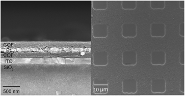
Besides ITO substrate, homogeneous COF thin films were also successfully grown on silicon, FTO, and platinum substrates (Fig. S11). The homogeneous morphologies and material compatibility of DAB–TFP COF thin films encourage us to design and fabricate COF-based hybrid stack multilayers via alternating deposition of DAB–TFP COF and deposition of other functional materials which, however, can be achieved easily by the well-established physical deposition techniques (see left part in Scheme 2). To test this strategy, a layer of DAB–TFP COF was first solvothermally deposited on an ITO substrate, a ∼120 nm Pt layer was subsequently sputter-coated on the COF layer, and another COF layer was finally deposited a top Pt layer. Fig. 4a showed a typical cross-sectional SEM image of the hybrid thin film prepared as described above. The brighter Pt layer can be clearly distinguished from the darker COF layers due to its higher electron density. The Pt layer is sandwiched between two COF layers (∼200 nm for each). Notably, the compositionally differing layers are in tight contact with each other, suggesting that the successive depositions occurred conformally. XRD measurements (Fig. 4b) corroborate the crystalline nature and identity of DAB–TFP COF in the hybrid film due to the presence of the broaden diffraction peak characteristic for π-stacking of layers at 27°. The existence of Pt in the hybrid film was confirmed by the appearance of diffraction peaks at 39.7° and 46.2° in the XRD pattern of the hybrid thin film and was also established by energy dispersive X-ray (EDX) analysis (Fig. S12). The thickness of Pt layer can be easily controlled by tuning the sputter coating time, whereas the thickness of COF layer can be increased by ∼200 nm per cycle via successive solvothermal deposition as above mentioned. Accordingly, the structure of the Pt/COF stack multilayers can be flexibly tuned. For example, a hybrid thin film consisting of three ∼200 nm COF layers separated by two ∼20 nm Pt layers has also been prepared in the similar manner (Fig. S13).


image file: c6ra07417k-s2.tif
Scheme 2 Schematic diagram of the processes for fabricating well-defined metal/COF stack multilayer via alternating physical deposition of metal materials and solvothermal deposition of COF (left) and for patterning thin films via photolithography and reactive ion etching (right).

image file: c6ra07417k-f4.tif
Fig. 4 (a) Cross-sectional SEM image of a hybrid film consisting of a ∼120 nm Pt layer sandwiched between two ∼200 nm COF layers fabricated on an ITO-coated glass substrate. (b) XRD pattern of the hybrid film showed in (a).

Because of the benefit of their homogeneous morphologies, the DAB–TFP COF thin films can be easily patterned by photolithography with high resolution. The strategy for patterning DAB–TFP COF photolithographically was illustrated in Scheme 2 (right). A ∼200 nm DAB–TFP COF film was firstly deposited on an ITO substrate, which was spin coated subsequently with a layer of photoresist. After exposure and development of photoresist, the exposed areas of COF film were etched away by (oxygen) reactive ion etching instead of by wet etching due to the excellent chemical stability of DAB–TFP COF.37 After removal of remaining resist by acetone, the sample was characterized using optical microscopy and scanning electron microscopy. The optical image (Fig. 5a) shows the large-area pattern consisting of an array of squares in the COF film. SEM image (Fig. 5b) indicates the squares are separated by about 10 μm and their edges are about 10 μm in length, which is consistent with the pattern feature of the custom-made chrome photomask (10 μm × 10 μm, with spacing of 10 μm). No discernible cracks or pinholes were observed in the resist-protected areas of the COF film, whereas the square areas were free of COF material.


image file: c6ra07417k-f5.tif
Fig. 5 (a) Optical image and (b) SEM image of patterned COF thin film on ITO substrate.

Conclusion

In summary, DAB–TFP COF thin films were successfully prepared on several substrates by solvothermal deposition method. With the layered 2D structure, DAB–TFP COF trends to form oriented thin film on substrates during the solvothermal growth. The oriented COF thin films appear dense, flat, crack-free, and uniform in thickness. Due to their chemical stability, material compatibility, and homogeneous morphologies, DAB–TFP COF thin films not only can be easily patterned by photolithography and RIE, but also can be integrated in well-defined metal/COF stack multilayers by alternating metal and COF depositions. Our strategies for engineering COF thin films are straightforward, compatible, and applicable to other COFs to realize some basic structures required for device applications.

Acknowledgements

This work is supported by Collaborative Innovation Center of Suzhou Nano Science and Technology, the National Natural Science Foundation of China (grant number 21371127), a start-up fund from Soochow University, a project funded by the Priority Academic Program Development of Jiangsu Higher Education Institutions (PAPD), and the Young Thousand Talented Program. The authors thank beamline BL14B1 (Shanghai Synchrotron Radiation Facility) for providing the beam time.

Notes and references

  1. A. P. Côté, A. I. Benin, N. W. Ockwig, M. O'Keeffe, A. J. Matzger and O. M. Yaghi, Science, 2005, 310, 1166–1170 CrossRef PubMed.
  2. H. M. El-Kaderi, J. R. Hunt, J. L. Mendoza-Cortés, A. P. Côté, R. E. Taylor, M. O'Keeffe and O. M. Yaghi, Science, 2007, 316, 268–272 CrossRef CAS PubMed.
  3. S.-Y. Ding and W. Wang, Chem. Soc. Rev., 2013, 42, 548–568 RSC.
  4. X. Feng, X. Ding and D. Jiang, Chem. Soc. Rev., 2012, 41, 6010–6022 RSC.
  5. A. Nagai, Z. Guo, X. Feng, S. Jin, X. Chen, X. Ding and D. Jiang, Nat. Commun., 2011, 2, 536,  DOI:10.1038/ncomms1542.
  6. H. Furukawa and O. M. Yaghi, J. Am. Chem. Soc., 2009, 131, 8875–8883 CrossRef CAS PubMed.
  7. J. L. Mendoza-Cortés, T. A. Pascal and W. A. Goddard, J. Phys. Chem. A, 2011, 115, 13852–13857 CrossRef PubMed.
  8. C. J. Doonan, D. J. Tranchemontagne, T. G. Glover, J. R. Hunt and O. M. Yaghi, Nat. Chem., 2010, 2, 235–238 CrossRef CAS PubMed.
  9. H. Lu, C. Wang, J. Chen, R. Ge, W. Leng, B. Dong, J. Huang and Y. Gao, Chem. Commun., 2015, 51, 15562–15565 RSC.
  10. Q. Fang, S. Gu, J. Zheng, Z. Zhuang, S. Qiu and Y. Yan, Angew. Chem., Int. Ed., 2014, 53, 2878–2882 CrossRef CAS PubMed.
  11. H. Xu, J. Gao and D. Jiang, Nat. Chem., 2015, 7, 905–912 CrossRef CAS PubMed.
  12. R. Gomes and A. Bhaumik, RSC Adv., 2016, 6, 28047–28054 RSC.
  13. H. Zhao, Z. Jin, H. Su, X. Jing, F. Sun and G. Zhu, Chem. Commun., 2011, 47, 6389–6391 RSC.
  14. Q. Fang, J. Wang, S. Gu, R. B. Kaspar, Z. Zhuang, J. Zheng, H. Guo, S. Qiu and Y. Yan, J. Am. Chem. Soc., 2015, 137, 8352–8355 CrossRef CAS PubMed.
  15. V. S. Vyas, F. Haase, L. Stegbauer, G. Savasci, F. Podjaski, C. Ochsenfeld and B. V. Lotsch, Nat. Commun., 2015, 6, 8508,  DOI:10.1038/ncomms9508.
  16. C. R. DeBlase, K. E. Silberstein, T.-T. Truong, H. D. Abruña and W. R. Dichtel, J. Am. Chem. Soc., 2013, 135, 16821–16824 CrossRef CAS PubMed.
  17. F. Xu, H. Xu, X. Chen, D. Wu, Y. Wu, H. Liu, C. Gu, R. Fu and D. Jiang, Angew. Chem., Int. Ed., 2015, 54, 6814–6818 CrossRef CAS PubMed.
  18. D. D. Medina, V. Werner, F. Auras, R. Tautz, M. Dogru, J. Schuster, S. Linke, M. Döblinger, J. Feldmann, P. Knochel and T. Bein, ACS Nano, 2014, 8, 4042–4052 CrossRef CAS PubMed.
  19. S.-L. Cai, Y.-B. Zhang, A. B. Pun, B. He, J. Yang, F. M. Toma, I. D. Sharp, O. M. Yaghi, J. Fan, S.-R. Zheng, W.-G. Zhang and Y. Liu, Chem. Sci., 2014, 5, 4693–4700 RSC.
  20. C. R. DeBlase, K. Hernández-Burgos, K. E. Silberstein, G. G. Rodríguez-Calero, R. P. Bisbey, H. D. Abruña and W. R. Dichtel, ACS Nano, 2015, 9, 3178–3183 CrossRef CAS PubMed.
  21. B. Yang, J. Björk, H. Lin, X. Zhang, H. Zhang, Y. Li, J. Fan, Q. Li and L. Chi, J. Am. Chem. Soc., 2015, 137, 4904–4907 CrossRef CAS PubMed.
  22. X.-H. Liu, C.-Z. Guan, S.-Y. Ding, W. Wang, H.-J. Yan, D. Wang and L.-J. Wan, J. Am. Chem. Soc., 2013, 135, 10470–10474 CrossRef CAS PubMed.
  23. D. D. Medina, J. M. Rotter, Y. Hu, M. Dogru, V. Werner, F. Auras, J. T. Markiewicz, P. Knochel and T. Bein, J. Am. Chem. Soc., 2015, 137, 1016–1019 CrossRef CAS PubMed.
  24. J. I. Feldblyum, C. H. McCreery, S. C. Andrews, T. Kurosawa, E. J. G. Santos, V. Duong, L. Fang, A. L. Ayzner and Z. Bao, Chem. Commun., 2015, 51, 13894–13897 RSC.
  25. J. W. Colson, A. R. Woll, A. Mukherjee, M. P. Levendorf, E. L. Spitler, V. B. Shields, M. G. Spencer, J. Park and W. R. Dichtel, Science, 2011, 332, 228–231 CrossRef CAS PubMed.
  26. E. L. Spitler, J. W. Colson, F. J. Uribe-Romo, A. R. Woll, M. R. Giovino, A. Saldivar and W. R. Dichtel, Angew. Chem., Int. Ed., 2012, 51, 2623–2627 CrossRef CAS PubMed.
  27. E. L. Spitler, B. T. Koo, J. L. Novotney, J. W. Colson, F. J. Uribe-Romo, G. D. Gutierrez, P. Clancy and W. R. Dichtel, J. Am. Chem. Soc., 2011, 133, 19416–19421 CrossRef CAS PubMed.
  28. J. W. Colson, J. A. Mann, C. R. DeBlase and W. R. Dichtel, J. Polym. Sci., Part A: Polym. Chem., 2015, 53, 378–384 CrossRef CAS.
  29. A. d. l. P. Ruigómez, D. Rodríguez-San-Miguel, K. C. Stylianou, M. Cavallini, D. Gentili, F. Liscio, S. Milita, O. M. Roscioni, M. L. Ruiz-González, C. Carbonell, D. Maspoch, R. Mas-Ballesté, J. L. Segura and F. Zamora, Chem.–Eur. J., 2015, 21, 10666–10670 CrossRef PubMed.
  30. L. D. Bonifacio, B. V. Lotsch, D. P. Puzzo, F. Scotognella and G. A. Ozin, Adv. Mater., 2009, 21, 1641–1646 CrossRef CAS.
  31. M. C. Fuertes, F. J. López-Alcaraz, M. C. Marchi, H. E. Troiani, V. Luca, H. Míguez and G. J. A. A. Soler-Illia, Adv. Funct. Mater., 2007, 17, 1247–1254 CrossRef CAS.
  32. S. Y. Choi, M. Mamak, G. von Freymann, N. Chopra and G. A. Ozin, Nano Lett., 2006, 6, 2456–2461 CrossRef CAS PubMed.
  33. G. Lu, O. K. Farha, W. Zhang, F. Huo and J. T. Hupp, Adv. Mater., 2012, 24, 3970–3974 CrossRef CAS PubMed.
  34. F. M. Hinterholzinger, A. Ranft, J. M. Feckl, B. Rühle, T. Bein and B. V. Lotsch, J. Mater. Chem., 2012, 22, 10356–10362 RSC.
  35. J. Liu, E. Redel, S. Walheim, Z. Wang, V. Oberst, J. Liu, S. Heissler, A. Welle, M. Moosmann, T. Scherer, M. Bruns, H. Gliemann and C. Wöll, Chem. Mater., 2015, 27, 1991–1996 CrossRef CAS.
  36. A. Ranft, F. Niekiel, I. Pavlichenko, N. Stock and B. V. Lotsch, Chem. Mater., 2015, 27, 1961–1970 CrossRef CAS.
  37. S. Kandambeth, A. Mallick, B. Lukose, M. V. Mane, T. Heine and R. Banerjee, J. Am. Chem. Soc., 2012, 134, 19254–19257 CrossRef PubMed.
  38. R. N. Gunasinghe, D. G. Reuven, K. Suggs and X.-Q. Wang, J. Phys. Chem. Lett., 2012, 3, 3048–3052 CrossRef CAS PubMed.

Footnote

Electronic supplementary information (ESI) available. See DOI: 10.1039/c6ra07417k

This journal is © The Royal Society of Chemistry 2016
Click here to see how this site uses Cookies. View our privacy policy here.