In2O3-functionalized MoO3 heterostructure nanobelts with improved gas-sensing performance

Su Zhang, Peng Song*, Jia Zhang, Zhuoqi Li, Zhongxi Yang and Qi Wang*
School of Material Science and Engineering, University of Jinan, Jinan 250022, China. E-mail: mse_songp@ujn.edu.cn; mse_wangq@ujn.edu.cn

Received 20th March 2016 , Accepted 16th May 2016

First published on 18th May 2016


Abstract

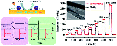
A novel heterostructure of In2O3 nanoparticle-functionalized MoO3 nanobelts was synthesized via a simple solution method. The phase purity, morphology and structure of the as-prepared In2O3-functionalized MoO3 heterostructure nanobelts were characterized by X-ray diffraction (XRD), scanning electron microscopy (SEM), transmission electron microscopy (TEM), and X-ray photoelectron spectroscopy (XPS). To demonstrate the potential applications of such In2O3/MoO3 composites, the as-prepared products were used to fabricate a gas sensor that was then investigated for gas-sensing performances. Results of the test showed that the response of In2O3 nanoparticle-functionalized MoO3 nanobelts against 10 ppm trimethylamine (TMA) is up to 31.69 at the working temperature of 260 °C, which is higher than that of bare MoO3 nanobelts. Moreover, the In2O3-functionalized MoO3 heterostructure sensor also exhibits excellent selectivity and rapid response and recovery speed. Such behaviors are attributed to the combination of In2O3 nanoparticles and uniformly decorated MoO3 nanobelts endowing a fascinating sensing performance for a novel sensing material, which may provide a new strategy to enhance the performance of sensing materials in the application of gas sensors.


Introduction

Metal oxide semiconductors have been extensively used for gas sensors owing to their high sensitivity, fast sensing, and simple and cheap fabrication.1–3 Among these metal oxides, molybdenum trioxide (MoO3), an important n-type semiconductor with a band gap of approximately 2.39–2.9 eV, is an excellent candidate for gas sensing applications.4–8 To optimize the gas performance of MoO3, a large amount of effort has been made to control the morphology and size of MoO3 nanostructures such as nanorods,9 nanoplates,10 nanobelts,11 nanofilms,12 nanoflowers,13 hollow spheres,14 and hierarchical structures15 etc. Among these MoO3 based nanomaterials, one-dimensional (1D) nanostructures with large surface-to-volume ratios have recently received a lot of attention for application as gas sensors. For example, E. Comini et al. have prepared MoO3 nanobelts via infrared irradiation heating of a Mo foil in a synthetic air atmosphere at atmospheric pressure, which showed high response to ethanol and CO.16 S. L. Bai et al. have synthesized MoO3 nanobelts by a simple probe ultrasonic approach, which exhibited a high response of 102.9 to 40 ppm NO2.17 Despite the promising potential of 1D MoO3 nanostructures for gas sensor applications, some aspects such as improvement of gas responses, low selectivity, and high working temperatures are persistent challenges to their actual implementation.

As we know, designing a heterojunction structure between different band gap and energy level semiconducting materials is an effective way to enhance the gas sensing performance of metal oxide semiconductors.18–22 Recently, it has been found that designing a heterojunction structure by combining 1D MoO3 nanostructures with other metal oxide semiconductors would be a significant route to enhance their gas response. For instance, T. S. Wang et al. reported 1D nanocomposite consists of n-type α-MoO3 nanobelts decorated with p-type CuO nanoparticles, and the p–n junction nanocomposite exhibited great enhanced H2S gas sensing properties.23 Y. J. Chen et al. have fabricated crystalline α-MoO3/TiO2 core/shell nanorods by a hydrothermal method and subsequent annealing processes, which showed enhanced sensing properties to ethanol vapor compared to bare α-MoO3 nanorods.24 Q. Wang et al. have prepared α-MoO3-In2O3 core–shell nanorods by a facile hydrothermal method. The one-dimensional core–shell nanostructures present good performance, which indicate that core–shell nanostructures with synergistic effects are good candidates for the anode of lithium ion batteries.25 Based on the above discussion, controlling the morphology and building a heterojunction structure at the same time is expected to be an effective way to enhance its gas response. However, such a kind of important and interesting topic has not yet been fully investigated.

Indium oxide (In2O3), as a typical n-type metal oxide semiconductor with a wide direct band gap of 3.5–3.7 eV, has received extensive attention because of its unique physical and chemical properties, which have led to excellent performance in the application of gas sensors.26–29 Recently, L. N. Han et al. found that gas sensors based on In2O3 nanoparticles-sensitized flowerlike ZnO exhibited significant gas response to HCHO under the visible light illumination.30 H. J. Kim et al. reported a dramatic enhancement in ethanol sensing characteristics of NiO hollow nanostructures via decoration with In2O3 nanoclusters.31 It can be seen that design and synthesis In2O3/MoO3 nanocomposites will have importantly scientific and practical significance. However, to the best of our knowledge, the gas-sensing properties of In2O3/MoO3 composite system have never been reported. In this study, we report the synthesis of MoO3 nanobelts with regular morphology via a facile hydrothermal route. In2O3 nanoparticles were subsequently decorated on the MoO3 nanobelts and formed a heterojunction structure. The microstructure and gas-sensing performance were systematically investigated.

Experimental

Preparation of pure MoO3 nanobelts and In2O3-functionalized MoO3 heterostructure

All the reagents we used in this experiment were of analysis grade and used without further purification. MoO3 nanobelts were synthesized by a hydrothermal route. First, we calcined ammonium heptamolybdenum tetrahydrate (AHM; (NH4)6Mo7O24·4H2O) at 500 °C for 4 h to obtain MoO3 powder. Subsequently, 3.6 g of as-obtained MoO3 powder was added to 27 mL of 30% aqueous H2O2 and continuous stirring until the powder was completely dissolved, then 13 mL of concentrated nitric acid and 85 mL deionized water were added to the mixed solution, continuous stirred to transform the yellow suspension to yellow transparent solution under room temperature. 35 mL of the mixed solution was transferred to a Teflon-lined stainless steel autoclave for 45 h at 170 °C. After completion of the hydrothermal reaction, the precipitates were collected by centrifugation, and washed several times with deionized water and absolute ethanol, then dried at 60 °C for 6 h. 0.024 g In(NO3)3 was dissolved in 100 mL water to form a homogeneous solution. Then 50 mg as-obtained MoO3 nanobelts were washed by 20 mL In(NO3)3 aqueous solution three times. The precipitates were dried at 60 °C for and then annealed at 500 °C for 2 h. Finally, we obtained the In2O3-functionalized MoO3 heterostructure.

Characterization

To examine the crystal structure and phase composition of as-prepared In2O3-functionalized MoO3 heterostructure nanobelts sample, we employed the X-ray diffraction (XRD, D8 X-ray diffractometer, λ = 0.15418 nm). The morphology and internal structure of the products were observed by field-emission scanning electronic microscope (FESEM, FEI Company, QUANTA FEG 250) and transmission electron microscope (TEM, Hitachi H-800). Low-magnification TEM images, high-resolution TEM (HRTEM) images were obtained. The energy-dispersive X-ray spectroscopy (EDS) analysis was analyzed by the FESEM attachment. The X-ray photoelectron spectra (XPS) were obtained on an X-ray photoelectron spectrometer (PHI 5300) to determine the electronic structure of the surface of In2O3/MoO3 nanocomposites.

Gas-sensing properties test

First of all, we fabricated the gas sensors based on pure MoO3 and In2O3-functionalized MoO3 heterostructure. The as-obtained samples were firstly mixed with ethanol to form slurry which had a certain viscosity, and then coated on a prefabricated alumina tube (attached with a pair of gold electrodes and Pt wires) by a small brush to form a thick film. We put a Ni–Cr resistor (diameter = 0.5 mm, resistance = 35 Ω) in the inner alumina ceramic tube to provide the working temperature for the gas sensor device. After aged in the air at 300 °C for at least 24 h, we could obtain a typical indirectly-heated gas sensor, and then the gas sensors were put into the test chamber. The gas-sensing properties were performed on a computer controlled WS-30A system (Weisheng Electronics Co. Ltd., Henan, China). A typical testing procedure was as follows: The as-fabricated sensors were put into a glass chamber which the capacity was 18 L. As the resistances of all the sensors were stable, the target gas or liquid was injected into glass chamber by a micro-injector and mixed with air quickly. For the target gases obtained from liquid, the concentration of target gas was calculated by the following formula,
 
C = (22.4 × ρ × d × V1)/(M × V2) (1)
where C (ppm) is the target gas concentration, ρ (g mL−1) is the density of the liquid, d is the purity of the liquid, V1 (μL) and V2 (L) are the volume of the liquid and glass chamber, respectively. M (g mol−1) is the molecular weight of the liquid. We can adjust the heating voltage (Vheating) to control the working temperature. During the test process, the working voltage was set to a fixed value which was 5 V. By monitoring the voltage of reference resistor (Voutput), the response of the sensor in air or in a test gas could be measured. The sensor response was defined as the following formula,
 
Response = Rgas/Rair (2)
Rair and Rgas are the resistances in the air and target gas, respectively. In addition, the response/recovery time was expressed to reach 90% of the overall resistance change.

Results and discussion

In order to determine the phase composition of as-prepared samples, we employed XRD analysis to obtain its XRD patterns. Fig. 1 shows the XRD patterns of the pure MoO3 and In2O3-functionalized MoO3 heterostructure samples. As we can see from the XRD pattern, all diffraction peaks of MoO3 in the pattern can be indexed to literature values (JCPDS card no. 05-0508). This indicates that the as-obtained products possess high purity and without other impurities mixed. For the XRD pattern of In2O3-functionalized MoO3 samples, compared with pure MoO3, some new diffraction peaks are appeared, which can be indexed to In2O3 standard card (JCPDS no. 06-0416), these additional peaks are marked by circles. The diffraction peaks of In2O3 are corresponding to (200), (211), (321) and (440). As can be seen from the patterns, there is no peak shift and other miscellaneous peaks, which demonstrates that we have obtained pure In2O3-functionalized MoO3 heterostructure.
image file: c6ra07292e-f1.tif
Fig. 1 XRD patterns of the pure MoO3 and In2O3-functionalized MoO3 heterostructure.

The morphology and nanostructures of the as-obtained In2O3-functionalized MoO3 heterostructure were observed by scanning electronic microscope (SEM) and transmission electron microscope (TEM). Fig. 2 shows the SEM images of MoO3 nanobelts (a, b) and In2O3-functionalized MoO3 heterostructure (c, d). EDS spectrum of In2O3-functionalized MoO3 heterostructure (e). From Fig. 2(a), we can see that the MoO3 samples are composed of approximately uniform nanobelts with an average size of width and thickness. Morphology of as-prepared MoO3 nanobelts is extremely unified. High-resolution SEM images of MoO3 nanobelts are showed in Fig. 2(b). As we can see, the surfaces of the pure MoO3 nanobelts are very smooth and without impurity. Then, after washing with the In(NO3)3 solution, the MoO3 nanobelts are coarser than those of pure MoO3 as shown in Fig. 2(c) and (d). From the images we can see that there are many In2O3 nanoparticles attach on the surface of the MoO3 nanobelts, the size and distribution of these In2O3 nanoparticles are very uniform. They are evenly distributed on each MoO3 nanobelts. In addition, we employed energy-dispersive X-ray spectroscopy (EDS) analysis to determine the elements composition of the as-obtained samples. As shown in Fig. 2(e), the EDS pattern indicates that the as-prepared samples are consisted of Mo, In and O elements, and the ratio of In element is about 1.01 mol%. We can also find that the In2O3 nanoparticles are evenly loaded on the surface of MoO3 nanobelts. Based on the previous results, we inferred that the In2O3 nanoparticles have formed and eventually attached on the surface of the MoO3 nanobelts.


image file: c6ra07292e-f2.tif
Fig. 2 SEM images of MoO3 nanobelts (a, b) and In2O3-functionalized MoO3 heterostructure (c, d). EDS spectrum of In2O3-functionalized MoO3 heterostructure (e).

In order to obtain more detailed information about the internal structure and morphology of the as-prepared samples, The TEM micrographs of In2O3-functionalized MoO3 heterostructure samples are shown in Fig. 3. As we can see in Fig. 3(a) and (b), the width of MoO3 nanobelts is about 200–300 nm, and we can see the thickness is about 75–80 nm from SEM images. The MoO3 nanobelts surface is uniformly attached with many In2O3 nanoparticles. And we can find out that the MoO3 nanobelts are solid structure and they also do not possess porous structure. From Fig. 3(c) we can see that the size of these In2O3 nanoparticles attached on MoO3 nanobelts surface is about 50–60 nm. The images of lattice fringe of the In2O3-functionalized MoO3 heterostructure samples are shown in Fig. 3(d), the lattice fringe spacing values of the In2O3 and MoO3 are about 0.506 nm and 0.199 nm, respectively. These results suggest that the as-obtained samples are well-crystallized with the In2O3 and MoO3 on the nanoscale, which is beneficial to electron transmission between MoO3 nanobelts and In2O3 nanoparticles on the surface.


image file: c6ra07292e-f3.tif
Fig. 3 TEM images of the In2O3-functionalized MoO3 heterostructure (a, b); high-resolution TEM images of In2O3-functionalized MoO3 heterostructure (c, d).

Fig. 4 presents the XPS spectra of as-obtained In2O3-functionalized MoO3 heterostructure samples. As shown in Fig. 4(a), the XPS spectra indicates that there exist Mo, O, In and some organic contamination (low intensity C 1s signal) on the surface. The binding energies are calibrated by C 1s (284.8 eV). Fig. 4(b) shows Mo 3d spectrum, from the spectrum we can see the 5/2–3/2 spin–orbit doublet for two oxidation sates. The most intense peak is located at BE = 232.5 eV whereas the low intensity is located at BE = 235.5 eV. However the binging energy of the In2O3-functionalized MoO3 heterostructure surface is different with the pure MoO3,32,33 this is due to the In2O3 that attached on the surface of MoO3, these In2O3 nanoparticles change the edge of the Fermi level of Mo ions, but this we can confirm these peaks are characteristic peaks of Mo6+. It indicates that Mo ions present as Mo6+ on the surface of samples. Fig. 4(c) shows the O 1s spectrum, there is a most intense peak at BE = 530.5 eV assigned to the O2− ions of the oxide layer. In the Fig. 4(d), the peak positions of In 3d3/2 (BE = 452 eV) and In 3d5/2 (BE = 444.3 eV) are located at 452.5 eV and 444.6 eV, which both moved to a higher energy direction, indicates that the chemical environment of In atoms have changed. It is due to the interaction of chemisorption oxygen and In atoms, enhance the bond of In–O.


image file: c6ra07292e-f4.tif
Fig. 4 XPS spectra of In2O3-functionalized MoO3 heterostructure: (a) wide XPS spectra of In2O3-functionalized MoO3 heterostructure; (b) Mo 3d spectra; (c) O 1s spectra; (d) In 3d spectra.

Gas sensing properties

As we know, the working temperature of a sensor plays an important role for gas-sensing properties of as-prepared samples. Fig. 5 presents the relationship between responses and working temperature of the sensors based on pure MoO3 and In2O3-functionalized MoO3 heterostructure to 10 ppm of trimethylamine (TMA). The working temperature range we tested is from 180 to 300 °C. As we can see, with the increasing of working temperature, the response of sensors based on pure MoO3 and In2O3-functionalized MoO3 heterostructure both become higher, and the highest response value appears at 260 °C. The maximum response values of pure MoO3 and In2O3-functionalized MoO3 heterostructure sensors are about 18.34 and 31.69, respectively. Then we continue to increase the working temperature, the response values of two sensors both significantly decreased. So we can infer that the optimum working temperature of the sensors based on pure MoO3 and In2O3-functionalized MoO3 heterostructure to TMA is 260 °C. Obviously, the response of In2O3-functionalized MoO3 heterostructure sensor is significantly higher than pure MoO3 sensor, which exactly verified the enhancement function of the In2O3 nanoparticles.
image file: c6ra07292e-f5.tif
Fig. 5 Response of sensors based on pure MoO3 and In2O3-functionalized MoO3 heterostructure to 10 ppm of TMA at different working temperature.

The gas-sensing properties of pure MoO3 and In2O3-functionalized MoO3 heterostructure sensors were investigated by detecting 10 ppm of TMA under the optimum operating temperature. The response and recovery curves of the sensors based on pure MoO3 and In2O3-functionalized MoO3 heterostructure to 10 ppm of TMA at 260 °C is shown in Fig. 6(a), we can see that the response and recovery time of pure MoO3 and In2O3-functionalized MoO3 heterostructure sensors are almost same, both are about 6 s and 9 s, respectively. Although attached In2O3 nanoparticles have no significant impact on the response and recovery time, but we can find out that after coated with the In2O3 nanoparticles, the response of the as-fabricated sensors has significantly increased. We injected different concentration of TMA (5–500 ppm) into the measuring chamber at the optimum working temperature, the resulting curves is shown in Fig. 6(b). It is obvious that the response of pure MoO3 and In2O3-functionalized MoO3 heterostructure sensors become higher as the concentration increases, and In2O3-functionalized MoO3 heterostructure shows much higher response than the pure MoO3 sensor. Even when the concentration is very low, the In2O3-functionalized MoO3 heterostructure sensor shows a good response, which means the sensor can be used to detect very low concentration of the target gas. The linear relationship of log(S − 1) − log(C) plot to TMA at 260 °C is shown in Fig. 6(c). From the image we can see that the response of pure MoO3 and In2O3-functionalized MoO3 heterostructure sensors exhibits a good linear relationship with the concentration, which is meaningful for the fabrication of practical TMA sensors. The slopes of pure MoO3 and In2O3-functionalized MoO3 heterostructure sensors are 0.520 and 0.485, respectively. It indicates that with the increase of gas concentration, the response of pure MoO3 sensor increase faster than In2O3-functionalized MoO3 heterostructure sensor. The stability of pure MoO3 and In2O3-functionalized MoO3 heterostructure sensors were tested at 260 °C, as shown in Fig. 6(d). The response values of pure MoO3 and In2O3-functionalized MoO3 heterostructure samples are reproducible for repeated testing cycles, and have no obvious change for the successional five tests to 10 ppm TMA.


image file: c6ra07292e-f6.tif
Fig. 6 (a) Response and recovery curves of the sensors based on pure MoO3 and In2O3-functionalized MoO3 heterostructure to 10 ppm of TMA at 260 °C. (b) The response and recovery curves of sensors upon exposure to 5–500 ppm of TMA at 260 °C. (c) The linear relationship of log(S − 1) − log(C) plot to TMA at 260 °C. (d) Response and recovery curves of sensors to 10 ppm TMA after 5 cycles of gas in and off at 260 °C.

Which means the pure MoO3 and In2O3-functionalized MoO3 heterostructure sensors both exhibit excellent response and reproducibility. Table 1 presents the comparison of gas-sensing performances between In2O3-functionalized MoO3 heterostructure nanobelts and other sensing materials toward trimethylamine. It can be clearly observed that the as-obtained In2O3-functionalized MoO3 heterostructure nanobelts based sensor possesses excellent sensing properties compared with other sensors.7,34–38 Therefore, it can infer that the sensors based on the In2O3-functionalized MoO3 heterostructure nanobelts displays excellent gas-sensing performances towards trimethylamine, it may use as a potential material in many fields.

Table 1 Responses to TMA of some sensors reported in the literature
Sensing materials Operating temperature (°C) Trimethylamine (ppm) Response Response/Recovery times (s) Ref.
In2O3-functionalized MoO3 heterostructure nanobelts 260 10 31.69 6/9 Present study
MoO3 microrods 300 1 8 8/9 7
MoO3 nanoplates 300 5 8.22 34
ZnO-doped SnO2 nanoparticles 330 50 125 2/5 35
NiO/ZnO nanofibers 260 100 100 5/13 36
α-Fe2O3 nanorods/TiO2 nanofibers 250 50 13.9 0.5/1.5 37
In2O3 rod 340 5 5.9 5/10 38


Fig. 7 shows the histogram of the response of pure MoO3 and In2O3-functionalized MoO3 heterostructure sensors to 10 ppm of different gases. The sensors based on pure MoO3 and In2O3-functionalized MoO3 heterostructure both shows better gas-sensing properties to TMA compared with other gases. This result displays the sensors based on pure MoO3 and In2O3-functionalized MoO3 heterostructure both have good selectivity to TMA at 260 °C. It is obviously that the responses of In2O3-functionalized MoO3 heterostructure sensors to all of these gases are higher than the pure MoO3 sensor, especially to TMA. To summarize these conclusions, the study of In2O3-functionalized MoO3 heterostructure sensor is a very promising object, because it possesses high response and selectivity, good stability to TMA.


image file: c6ra07292e-f7.tif
Fig. 7 Response of sensors based on pure MoO3 and In2O3-functionalized MoO3 heterostructure at 260 °C to 10 ppm various gases.

As we know, In2O3 and MoO3 are both n-type metal oxide semiconductors. The gas-sensing mechanism can be proposed after summarizing lots of literatures. Due to the target gas molecules are adsorbed on the surface of the materials caused the change of material's resistance.39 During testing process, the pure MoO3 and In2O3-functionalized MoO3 heterostructure sensors are put in air surrounding at first, oxygen molecules in air can be adsorbed on the surface of MoO3 and In2O3-functionalized MoO3 heterostructure, these absorbed oxygen molecules will capture free electrons from the conduction band to form chemisorbed oxygen ions, such as O2, O, O2−.40 This progress can be expressed as the following equations:41

 
O2(gas) → O2(ads) (3)
 
O2(ads) + e → O2(ads) (4)
 
O2(ads) + e → 2O(ads) (5)
 
O(ads) + e → O2−(ads) (6)

The process of absorbing oxygen molecules will form a depletion layers on the surface of MoO3 and causes the increase of resistance of the sensors. When we injected TMA, a kind of reducing gas, the TMA molecules may react with the chemisorbed oxygen ions on the surface and give the free electrons back to the conduction band, leading to the decrease in the resistance of MoO3.42 The reaction between chemisorbed oxygen ions and TMA can be simply described as following:43

 
(CH3)3N + 21O = N2 + 9H2O + 6CO2 + 21e (7)

So we have obtained the high response of pure MoO3 and In2O3-functionalized MoO3 heterostructure sensors. However, through the above test results can be seen that the gas-sensing property of In2O3-functionalized MoO3 heterostructure sensor is better than pure MoO3 sensor. The reason of this phenomenon is the hetero-interface between the MoO3 nanobelts and In2O3 nanoparticles. The hetero-interface between the MoO3 and In2O3 may act as a catalytic during the reaction process, oxygen molecules are easily adsorbed on the hetero-interface.44 In addition, In2O3 and MoO3 are both typical n-type semiconductors, and their band gap are about 2.3 eV and 3.5 eV, respectively, they are broadly use as gas-sensing materials. Because of the existence of heterojunction, the free electrons can be transferred between the In2O3 and MoO3 quickly, and the trapped electrons will be transferred to absorbed oxygen molecules to form oxygen ions. In this process, the target gas is rapidly oxidized.45 Schematic diagram of gas-sensing mechanism is shown in Fig. 8. During the process of electrons transferring, In2O3 and MoO3 play a role as synergistic catalytic effect, which promote the efficiency of electrons transferring and improve the gas-sensing performance of the sensors. Thus, the In2O3-functionalized MoO3 heterostructure sensor possesses excellent properties compared with pure MoO3.


image file: c6ra07292e-f8.tif
Fig. 8 Schematic of sensing mechanism of In2O3-functionalized MoO3 heterostructure.

In addition, the reason for high selectivity to TMA can be explained. The response of materials is related to the reducing ability and the adsorbing ability of detected gas.46 CH3– is a kind of electron-donating group, the electron cloud density around N atoms in TMA is higher than O atoms in ethanol, acetone, formaldehyde, etc. The high attractive force between N atoms and Mo6+ can promote the adsorption of TMA gas molecules on the surface. As we know, the bond energy is also important to stability of a material, the compound has higher bond energy will be harder to break. The bond strengths of C–H, C–C, C–N, C[double bond, length as m-dash]O and O–H are 411, 345, 307, 748.2, 462 kJ mol−1, respectively.47,48 The bond energy of C–N in TMA is lowest among these detected gas, which means the TMA is an unstable compound, and its reducing ability should be higher than other detected gas.

Conclusions

In summary, MoO3 nanobelts and In2O3-functionalized MoO3 heterostructure were successfully prepared by a simple solution route. The diameter of as-obtained MoO3 nanobelts is about 200–300 nm, and the size of In2O3 nanoparticles on the MoO3 surface is 45–50 nm. The sensors based on pure MoO3 and In2O3-functionalized MoO3 heterostructure demonstrated great response and selectivity to 10 ppm TMA, and their optimum working temperature is 260 °C. Furthermore, the In2O3-functionalized MoO3 heterostructure sensor possesses better sensing properties compared with pure MoO3 sensor. At 260 °C, the response values of pure MoO3 and In2O3-functionalized MoO3 heterostructure sensors to 10 ppm TMA are 18.34 and 31.69, respectively. The response and recovery times of two sensors are both 6 and 9 s. These results indicate the potential applications of the In2O3-functionalized MoO3 heterostructure in detecting TMA gas.

Acknowledgements

This work was financially supported by National Natural Science Foundation of China (No. 61102006 and 51172095), Natural Science Foundation of Shandong Province, China (No. ZR2015EM019 and ZR2014EL006), and Shandong Province Higher Educational Science and Technology Program (No. J15LA56).

Notes and references

  1. A. Tricoli, M. Righettoni and A. Teleki, Angew. Chem., Int. Ed., 2010, 49, 7632 CrossRef CAS PubMed.
  2. N. Yamazoe, G. Sakai and K. Shimanoe, Catal. Surv. Asia, 2003, 7, 63 CrossRef CAS.
  3. N. Barsan, D. Koziej and U. Weimar, Sens. Actuators, B, 2007, 121, 18 CrossRef CAS.
  4. S. S. Sun, E. Prabhu, V. Jayaraman, K. I. Gnanasekar, T. K. Seshagiri and T. Gnanasekaran, Sens. Actuators, B, 2004, 101, 161 CrossRef.
  5. S. Barazzouk, R. P. Tandon and S. Hotchandani, Sens. Actuators, B, 2006, 119, 691 CrossRef CAS.
  6. W. S. Kim, H. C. Kim and S. H. Hong, J. Nanopart. Res., 2010, 12, 1889 CrossRef CAS.
  7. X. F. Chu, S. M. Liang, W. Q. Sun, W. B. Zhang, T. Y. Chen and Q. F. Zhang, Sens. Actuators, B, 2010, 148, 399 CrossRef CAS.
  8. C. Imawan, F. Solzbacher, H. Steffes and E. Obermeier, Sens. Actuators, B, 2000, 64, 193 CrossRef CAS.
  9. X. W. Lou and H. C. Zeng, Chem. Mater., 2002, 14, 4781 CrossRef CAS.
  10. H. X. Bai, X. H. Liu and Y. C. Zhang, Mater. Lett., 2009, 63, 100 CrossRef CAS.
  11. T. Xia, Q. Li, X. D. Liu, J. Meng and X. Q. Cao, J. Phys. Chem. B, 2006, 110, 2006 CrossRef CAS PubMed.
  12. S. S. Sun, E. Prabhu, V. Jayaraman, K. I. Gnanasekar, T. K. Seshagiri and T. Gnanasekaran, Sens. Actuators, B, 2003, 94, 189 CrossRef.
  13. G. G. Wei, W. P. Qin, D. S. Zhang, G. F. Wang, R. J. Kim, K. Z. Zheng and L. L. Wang, J. Alloys Compd., 2009, 481, 417 CrossRef CAS.
  14. Z. Q. Wang, H. F. Wang, C. Yang and J. H. Wu, Mater. Lett., 2010, 64, 2170 CrossRef CAS.
  15. H. H. Yan, P. Song, S. Zhang, Z. X. Yang and Q. Wang, RSC Adv., 2015, 5, 72728 RSC.
  16. E. Comini, L. Y. bao, Y. Brando and G. Sberveglieri, Chem. Phys. Lett., 2005, 407, 368 CrossRef CAS.
  17. S. L. Bai, S. Chen, L. Y. Chen, K. W. Zhang, R. X. Luo, D. Q. Li and C. C. Liu, Sens. Actuators, B, 2012, 174, 51 CrossRef CAS.
  18. D. R. Miller, S. A. Akbar and P. A. Morris, Sens. Actuators, B, 2014, 204, 250 CrossRef CAS.
  19. X. J. Zhang and G. J. Qiao, Appl. Surf. Sci., 2012, 258, 6643 CrossRef CAS.
  20. E. Comini, M. Ferroni, V. Guidi, G. Faglia, G. Martinelli and G. Sberveglieri, Sens. Actuators, B, 2002, 84, 26 CrossRef CAS.
  21. L. Xing, S. Yuan, Z. Chen, Y. Chen and X. Xue, Nanotechnology, 2011, 22, 1 Search PubMed.
  22. W. L. Zang, Y. X. Nie, D. Zhu, P. Deng, L. L. Xing and X. Y. Xue, J. Phys. Chem. C, 2014, 118, 9209 CAS.
  23. T. S. Wang, Q. S. Wang, C. L. Zhu, Q. Y. Ouyang, L. H. Qi, C. Y. Li, G. Xiao, P. Gao and Y. J. Chen, Sens. Actuators, B, 2012, 171–172, 256 CrossRef CAS.
  24. Y. J. Chen, G. Xiao, T. S. Wang, F. Zhang, Y. Ma, P. Gao, C. L. Zhu, E. D. Zhang, Z. Xu and Q. H. Li, Sens. Actuators, B, 2011, 155, 270 CrossRef CAS.
  25. Q. Wang, J. Sun, Q. Wang, D. A. Zhang, L. L. Xing and X. Y. Xue, J. Mater. Chem. A, 2015, 3, 5083 CAS.
  26. S. J. Kim, I. S. Hwang, J. K. Choi, Y. C. Kang and J. H. Lee, Sens. Actuators, B, 2011, 155, 512 CrossRef CAS.
  27. Q. Qi, P. P. Wang, J. Zhao, L. L. Feng, L. J. Zhou, R. F. Xuan, Y. P. Liu and G. D. Li, Sens. Actuators, B, 2014, 194, 440 CrossRef CAS.
  28. S. M. Wang, B. X. Xiao, T. Y. Yang, P. Wang, C. H. Xiao, Z. F. Li, R. Zhao and M. Z. Zhang, Sens. Actuators, B, 2013, 176, 405 CrossRef.
  29. A. Chaoumead, B. H. Joo, D. J. Kwak and Y. M. Sung, Appl. Surf. Sci., 2013, 275, 227 CrossRef CAS.
  30. L. N. Han, D. J. Wang, J. B. Cu, L. P. Chen, T. F. Jiang and Y. H. Lin, J. Mater. Chem., 2012, 22, 12915 RSC.
  31. H. J. Kim, H. M. Jeong, T. H. Kim, J. H. Chung, Y. C. Kang and J. H. Lee, ACS Appl. Mater. Interfaces, 2014, 6, 18197 CAS.
  32. D. Khemchand, N. S. Nupur and K. S. Prashant, CrystEngComm, 2011, 3, 4358 Search PubMed.
  33. J. Zhang, X. M. Bai and X. Li, Chin. J. Catal., 2009, 30, 1017 CrossRef CAS.
  34. Y. H. Cho, Y. N. Ko, Y. C. Kang, I. D. Kim and J. H. Lee, Sens. Actuators, B, 2014, 195, 189 CrossRef CAS.
  35. W. H. Zhang and W. D. Zhang, Sens. Actuators, B, 2008, 134, 403 CrossRef CAS.
  36. C. Li, C. H. Feng, F. D. Qu, J. Liu, L. H. Zhu, Y. Lin, Y. Wang, F. Li, J. R. Zhou and S. P. Ruan, Sens. Actuators, B, 2015, 207, 90 CrossRef CAS.
  37. Z. Lou, F. Li, J. N. Deng, L. L. Wang and T. Zhang, ACS Appl. Mater. Interfaces, 2013, 5, 12310 CAS.
  38. X. F. Lu, Q. Q. Yu, K. Wang, L. C. Shi, X. Liu, A. G. Qiu, L. Wang and D. L. Cui, Cryst. Res. Technol., 2010, 45, 557 CrossRef CAS.
  39. S. H. Park, S. H. Kim and G. J. Sun, Synthesis, ACS Appl. Mater. Interfaces, 2015, 7, 8138 CAS.
  40. M. Bagheri, N. F. Hamedani, A. R. Mahjoub, A. A. Khodadadi and Y. Mortazavi, Sens. Actuators, B, 2014, 191, 283 CrossRef CAS.
  41. F. B. Gu, L. Zhang, Z. H. Wang, D. M. Han and G. S. Guo, Sens. Actuators, B, 2014, 193, 669 CrossRef CAS.
  42. S. Yang, Y. L. Liu, W. Chen, W. Jin, J. Zhou, H. Zhang and G. S. Zakharova, Sens. Actuators, B, 2016, 226, 478 CrossRef CAS.
  43. C. Li, C. H. Feng, F. D. Qu, J. Liu, L. H. Zhu, Y. Lin, Y. Wang, F. Li, J. R. Zhou and S. P. Ruan, Sens. Actuators, B, 2015, 207, 90–96 CrossRef CAS.
  44. R. Zhang, L. L. Wang, J. N. Deng, T. T. Zhou and Z. Lou, Sens. Actuators, B, 2015, 220, 1224 CrossRef CAS.
  45. Y. V. Kaneti, Q. M. D. Zakaria, Z. J. Zhang, C. Y. Chen, J. Yue, M. S. Liu, X. C. Jiang and A. B. Yu, J. Mater. Chem. A, 2014, 2, 13283 CAS.
  46. E. X. Chen, H. R. Fu, R. Lin, Y. X. Tan and J. Zhang, ACS Appl. Mater. Interfaces, 2014, 6, 22871 CAS.
  47. X. F. Chu, S. M. Liang, W. Q. Sun, W. B. Zhang, T. Y. Chen and Q. F. Zhang, Sens. Actuators, B, 2010, 148, 399 CrossRef CAS.
  48. X. J. Luo, Z. Lou, L. L. Wang, X. J. Zheng and T. Zhang, New J. Chem., 2014, 38, 84 RSC.

Footnote

Electronic supplementary information (ESI) available: Gas response of In2O3-functionalized MoO3 heterostructure nanobelts toward NO2 gas. See DOI: 10.1039/c6ra07292e

This journal is © The Royal Society of Chemistry 2016