Encapsulation of epoxy and amine curing agent in PAN nanofibers by coaxial electrospinning for self-healing purposes

Rasoul Esmaeely Neisianyab, Saied Nouri Khorasani*a, Jeremy Kong Yoong Leebc and Seeram Ramakrishna*b
aDepartment of Chemical Engineering, Isfahan University of Technology, Isfahan 84156-83111, Iran. E-mail: saied@cc.iut.ac.ir; Tel: +98-3133915612
bCenter for Nanofibers and Nanotechnology, Department of Mechanical Engineering, Faculty of Engineering, 2 Engineering Drive 3, Singapore 117576, Singapore. E-mail: seeram@nus.edu.sg; Tel: +65-65162216
cLloyd's Register Global Technology Centre, 1 Fusionopolis Place, #09-11, Galaxis, Singapore 138522, Singapore

Received 10th March 2016 , Accepted 16th July 2016

First published on 18th July 2016


Abstract

Dual components of a self-healing epoxy system comprising an epoxy resin and its amine based curing agent were encapsulated in a polyacrylonitrile (PAN) shell via a coaxial electrospinning technique. The morphological study showed the electrospun core–shell nanofibers were smooth, continuous, and without beads, with average diameters measured to be 483 nm and 406 nm for encapsulated epoxy and amine nanofibers, respectively. Investigations into the nanofiber's chemical structure showed the successful encapsulation of the epoxy resin and amine curing agent in the PAN shell, retaining the chemical characteristics of the encapsulated components. The thermal characterization of the nanofibers reinforced these findings, showing a 24 wt% and 37 wt% availability of the epoxy resin and amine curing agent contained within the PAN nanofibers, respectively. In addition, DSC results showed that this system holds great promise for self-healing epoxy resins in composite applications, particularly because of its spontaneous room temperature curing characteristics.

1 Introduction

Self-healing polymeric materials first emerged from the work of White et al.1 who demonstrated the earliest instance of a material which could completely autonomously repair itself, based on a microcapsule approach. This innovation sparked an arms race of sorts in the field, with many other research groups developing self-healing materials capable of attaining even higher recovery responses.2–19 Generally, the approaches used to imbue polymeric materials with the autonomous healing ability takes two forms, encapsulation of the healing agents within microcapsules2–13 or within vascular channels,15–22 which are dispersed throughout the material. Between the two methods, the microcapsule based self-healing strategy has a severe limitation in that there is significant ambiguity in realizing complete healing and multiple repeated healing due to the lack of adequate healing agent at the site of damage, which could have been completely consumed before all the damage is repaired. Repeated healings would only be feasible through loading excess healing agent in the matrix that would not be depleted after the first healing occurs.23 Dry15et al. therefore pioneered a method which enabled multiple healings through delivering a large supply of liquid healing agents from a reservoir contained within tubular channels. It is worth noting both Motuku16 and Dry employed hollow tubular structures of dimensions appreciably larger than that of the reinforcement fibres in order to contain sufficient amounts of the healing agents. These healing agent containing vascular systems, with diameters in the order of millimetres, could therefore disrupt the composite structure and ultimately be responsible for initiating the failure of the composite, limiting their usefulness. In addition, several groups including Trask et al.18,19 and Williams et al.20 showed that the deployment of layers of hollow glass containing healing agents into glass fibre and carbon fibre epoxy composites allowed substantial recovery of the initial material's strength. The fibres used in their work had hollowness of 50%, and had smaller diameters than the earlier cited works, having diameters between 30–100 μm. The relationship between hollow fibre size and the strength of the composite is perhaps best illustrated by Kousourakis,24 whose work showed that relatively large fibre sizes correspondingly reduced the static strength of the material when aligned perpendicularly to the plies of the reinforcement fibre.

Encapsulation of healing agents within of small diameters has consequently received much attention from researchers. One approach invented by Park and his collaborators25 involved the fabrication of a self-healing coating by encapsulating two parts dimethylpolysiloxane in polyvinylpyrrolidone (PVP) via a two-step electrospinning method, and combining the resultant in a coating of acrylated polyurethane on a steel substrate. His research group demonstrated the utility and effectiveness of this electrospinning method by successfully encapsulating the healing agents within nanosized fibre channels. Another research group led by Sinha-Ray et al.26 reported the encapsulation of two healing agents, dicyclopentadiene (DCPD) and isophorone diisocyanate (IPDI), in PAN nanofibers. Additionally, Wu et al.27 employed coaxial electrospinning to encapsulate DCPD healing agents in PAN nanofibers, and successfully fabricated a hybrid material by layering plies of the electrospun nanofiber webs onto the reinforcement in an epoxy/carbon fibre composite. His results showed 100% recoverable mechanical properties of the samples approximately 2 hours after fracture, allowing sufficient time for the release of the healing agent, contacting the catalyst, and for polymerization to occur. Mitchell et al.28 also encapsulated an epoxy (healing agent) in polyvinyl alcohol (PVA) nanofibers via electrospinning, but his work focused more on the methodology of core–shell fibres production without further investigation on the healing performance and recovering efficiency. Further to these reported works, Lee and co-workers also used the electrospinning method to produce self-healing composites and coatings by encapsulating dimethylsiloxane (DMS) in PAN.29–33

Due to the industrial and commercial importance of epoxies in a host of applications and composite materials, the development of a self-healing epoxy system is of great interest, with its potential to provide a chemically and mechanically suitable matrix system to many epoxy composites and coatings in use today. Much of the reported literature concentrates on the encapsulation of epoxy resins and their corresponding curing agents in dual capsule healing systems.6–14 But there have not been any reported attempts at encapsulating the epoxy resin and curing agent in nanofibers. Furthermore, ability of certain amine based curing agent systems that allow for room temperature curing would be of great interest to many industries. Therefore, in this study, we propose the methodology for encapsulating an epoxy and an amine based curing agent in a PAN nanofiber through a coaxial electrospinning technique. The epoxy and curing agent systems were specifically selected for their low viscosity and room temperature curing ability to allow the liquid resin and curing agents to flow easily into the initiated cracks upon sustaining damage, react with each other, and initiate healing at room temperature.

2 Experimental materials & methods

2.1 Materials

Both PAN (polyacrylonitrile, Mw = 150 kDa) and DMF (N,N-dimethylformamide, 99.8%) were purchased from Sigma-Aldrich. The two components of the low-viscosity epoxy system, EPIKOTE™ Resin 240 and its amine based curing agent EPIKURE™ 3370, were purchased from Hexion and used without further purification. These components were separately supplied to the core of the coaxial needle, while a 9 wt% solution of PAN in DMF was supplied to the shell of the coaxial needle, yielding PAN encapsulated resin nanofibers, and PAN encapsulated curing agent nanofibers. The PAN solution was prepared by combining the appropriate quantities of polymer powder and DMF solvent in a scintillation vial, and stirred by a magnetic stirrer for 24 h at room temperature.

2.2 Coaxial electrospinning

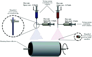
To perform coaxial electrospinning, a coaxial needle, supplied by Ramé-hart USA, comprising a 24 gauge inner needle and a 16 gauge outer needle was used. Fig. 1 shows the schematic illustration of the coaxial electrospinning process. The typical flow rate for the PAN shell material was 0.9 mL h−1, whereas for the core materials, flow rates of 0.06 mL h−1 for the epoxy resin, and 0.07 mL h−1 for the amine based curing agent were found to result in stable electrospinning. The distance between needle tip and collector was fixed at 15 cm for both encapsulating the resin and the curing agent, and a 15 kV direct current voltage was applied to induce the nanofibers formation from the solution.
image file: c6ra06434e-f1.tif
Fig. 1 Schematic illustration of the coaxial electrospinning.

2.3 Characterization

2.3.1 Morphological characterization. The surface morphology of the electrospun core–shell nanofiber mats was studied using a Hitachi S-4300 field emission scanning electron microscope (FESEM). To reveal the core–shell structure of the nanofibers and verify the successful encapsulation of the resin and curing agent within the PAN shell, we employed a JEM 2010F transmission electron microscope (TEM) operating at 200 kV.
2.3.2 Chemical and physical state of the components. Fourier transform infrared (FTIR) spectroscopy was used in order to probe the functional groups present in the core–shell nanofibers. The FTIR spectra was recorded on a Bio-Rad FTS-3500ARX FTIR spectrometer using the KBr pellets method in the range of wave numbers from 4000–500 cm−1. To eliminate the possibility of having unencapsulated epoxy and amine curing agent generating false positives during FTIR analysis, methanol was used to wash the electrospun nanofibers prior to the FTIR runs.

To attempt a quantitative assessment of the amount of encapsulated core material, a series of thermogravimetric analysis (TGA) experiments were performed using a Shimadzu DTG-60H TGA analyser. Methanol washing was again employed to remove the unencapsulated resins and curing agents from the surface of the nanofibers. The sample weight was approximately 10 mg of nanofibers for each TGA experiment, and each sample was obtained by careful excision from the collected electrospun mat with a new razor blade (cleaned with acetone), and deposited in 70 μl alumina crucibles. The TGA instrument was ramped at 10 °C min−1 from room temperature to 600 °C under argon gas at a flow rate of 50 mL min−1. Dynamic differential scanning calorimetry (DSC) studies were also carried out, using a Shimadzu DSC-60 thermal analysis instrument to examine the thermal characteristics and curing behaviour of the selected epoxy resin and amine based curing agent. The heating rate for the non-isothermal measurements was set at 10 °C min−1 from room temperature to 300 °C under argon gas at a flow rate of 50 mL min−1. Furthermore, temperatures of 30, 40, 50, and 60 °C were also used to conduct a study on the isothermal curing characteristics of the resin.

3 Results and discussion

3.1 Morphological characterization

Representative SEM images of the electrospun encapsulated epoxy and curing agent nanofibers are shown in Fig. 2(a, b, d and e), respectively. The nanofibers are sufficiently uniform in diameter, and exhibited no beading. The images were analysed using Image J. Averaged over 50 measurements, the average nanofiber diameter was measured to be 483 nm and 406 nm for encapsulated epoxy and amine nanofibers respectively. The standard deviation of nanofiber diameters was further determined to be 78 and 62 nm for epoxy and amine containing nanofibers respectively. Fig. 2(c and f) show the nanofiber diameter distribution of epoxy-PAN and amine based curing agent-PAN core–shell nanofibers, respectively. In addition, Fig. 2(g) illustrates the nanofiber damage, release of the encapsulated epoxy and curing agent, contact between the two components, and the resulting curing and solidification of the new resin. The red circles indicate the solidified epoxy after release from the damaged nanofibers.
image file: c6ra06434e-f2.tif
Fig. 2 SEM image of epoxy-PAN (core–shell) nanofibers at 5000 magnification (a), 10[thin space (1/6-em)]000 magnification (b), and its distribution of nanofibers diameters (c). Amine based curing agent-PAN (core–shell) nanofibers at 5000 magnification (d), 10[thin space (1/6-em)]000 magnification (e) and its distribution of nanofiber diameters (f), ruptured nanofibers leading to the release of encapsulated healing agents, and subsequent curing to obtain the solidified resin (circled) (g).

To further corroborate the core–shell structure of the nanofibers, TEM images were obtained as shown in Fig. 3(a) and (b) for epoxy and amine based cores, respectively. The TEM samples were prepared by depositing nanofibers onto a copper grid for a few seconds. The interfacial boundary lines between the core and the shell are clearly visible in both epoxy-PAN and amine based curing agent-PAN nanofibers. The diameter of the full epoxy-PAN core–shell nanofiber was measured to be approximately 496 nm, with the epoxy core having a diameter measured to be approximately 164 nm. In the curing agent-PAN nanofiber, the full core–shell nanofiber diameter and the amine core diameters were found to be ∼428 nm and ∼127 nm, respectively.


image file: c6ra06434e-f3.tif
Fig. 3 TEM image of epoxy-PAN (core–shell) nanofibers (a) and amine based curing agent-PAN (core–shell) nanofibers (b).

3.2 Chemical structure of nanofibers

The chemical structure of the epoxy and curing agent containing nanofibers was investigated by FTIR. Fig. 4(a) shows the IR spectra of the neat PAN, neat epoxy, and PAN encapsulated epoxy core–shell nanofibers. The FTIR spectrum of the neat PAN shell nanofibers exhibits a –C[triple bond, length as m-dash]N (stretch) absorption band at 2245 cm−1, while –CH2 absorption peaks appear at 2930 cm−1. For neat epoxy sample, the absorption peaks at 1254 and 911 cm−1 indicate the presence of C–O–C and epoxide groups, respectively. Characteristic peaks of both the epoxy and PAN appear in the FTIR spectrum of the core–shell nanofiber, clearly indicative of the encapsulation of epoxy by PAN, while the retention of the reactive functional groups suggest physical encapsulation, and the absence of chemical reactions between PAN and epoxy.
image file: c6ra06434e-f4.tif
Fig. 4 FT-IR spectra of epoxy-PAN nanofibers (a) and amine based curing agent-PAN nanofibers (b).

Fig. 4(b) shows the IR spectra of the neat PAN, neat curing agent, and curing agent containing PAN nanofibers. Similar to Fig. 4(a) the FTIR spectrum of the neat PAN shell nanofibers exhibits characteristic peaks at 2245 cm−1 and 2930 cm−1. For the amine based curing agent, absorption peaks for the N–H group could be located at 837, 1603, and 3360 cm−1. In addition, characteristic peaks of both PAN shell and the curing agent can be seen in the FTIR spectrum of the broken core–shell nanofiber, which indicate the successful encapsulation of the curing agent and the lack of chemical reactions between PAN and the amine based curing agent over the course of electrospinning.

3.3 Thermal stability of nanofibers

The thermal stability of the core–shell nanofiber is an important property which dictates its temperature performance limitations and suitability to be used as healing agents in self-healing resins. TGA is a complementary technique that can elucidate the composition and thermal stability of the nanofibers, providing a quantitative assessment of the amount of encapsulated core material, and the temperature at which thermal decomposition starts to occur. The epoxy containing PAN nanofibers and the curing agent containing nanofibers were tested along with four control samples, namely neat PAN (PAN powder before electrospinning), neat PAN nanofibers, neat epoxy resin, and neat amine based curing agent. The data obtained from these experiments are shown in Fig. 5(a) and (b) for the epoxy core and amine based curing agent core respectively.
image file: c6ra06434e-f5.tif
Fig. 5 Typical TGA curve for epoxy-PAN nanofibers (a) and amine based curing agent-PAN nanofibers (b).

Fig. 5(a) shows the superimposed TGA plots of the neat epoxy, neat PAN, neat PAN nanofibers, and encapsulated epoxy-PAN nanofiber. In the case of PAN, the shape of the TGA curve in an inert atmosphere possess two distinct mass loss steps.34 The first occurs at approximately 320 °C and is associated with nitrile oligomerization, which produces volatile products, e.g. NH3, HCN, CH3CN etc. that are driven off. The second stage of the PAN degradation occurs between 350–500 °C. In addition, there is an observed weight loss in neat PAN nanofibers at approximately 70–85 °C likely due the evaporation of residual DMF. The thermal decomposition of the epoxy resin occurs in the temperature range of 200–480 °C, and consists of two stages. In case of the epoxy containing nanofibers, the general thermal degradation pattern shows decomposition from 180 °C to 500 °C consisting of three stages. The epoxy content of the core–shell nanofibers has been approximated by considering the weight loss contributed from the PAN component of the core–shell nanofibers around 500 °C, using the weight loss from neat PAN as a baseline. The epoxy content in the core–shell nanofibers was thus observed to be approximately 24 wt%.

Similar to epoxy core, Fig. 5(b) shows the superimposed TGA plots of the neat amine based curing agent, neat PAN, neat PAN nanofibers, and core–shell nanofiber with the curing agent encapsulated in the core. The TGA curve of curing agent exhibits a one-step weight loss starting at 120 °C and continuing up to 290 °C. In case of the curing agent containing nanofibers, the general thermal degradation pattern shows decomposition from 185 °C to 500 °C consisting of two stages. By the same approximation, the curing agent content within the core–shell nanofibers was estimated to be approximately 37 wt%.

The theoretical composition of the encapsulated nanofiber samples can be determined from the prescribed mass flow rates in the electrospinning process28 since the volume flow rates of the materials and their densities are known. According to the electrospinning flow rates, the theoretical weight proportion of the cores were calculated to be 45% and 46% for epoxy resin and amine based curing agent cores respectively (assuming the complete evaporation of DMF solvent during the electrospinning process). However, the TGA derived compositions were significantly lower than predicted, coming in at 24% and 37%, respectively. This discrepancy suggests a portion of the core material is not encapsulated within nanofibers and were removed during the washing with methanol. On the other hand, comparing the encapsulated epoxy wt% and curing agent wt% reveals that encapsulation of the curing agent occurs relatively easier compared to the epoxy resin, with a smaller discrepancy between the measured and expected nanofiber composition. This is likely due to the different solution parameters such as viscosity and conductivity35 affecting the coaxial electrospinning process.

3.4 Curing studies

The reaction between epoxy and the curing agent is exothermic in nature; hence, the self-healing process of the dual-component core–shell nanofibers can be well observed by monitoring the changes in thermal behaviour of the samples by DSC. The samples for DSC studies were put in the DSC pan, crimped, and then immediately tested. Fig. 6(a) shows the curing of the neat epoxy resin (EPIKOTE™ Resin 240) with neat amine based curing agent (EPIKURE™ 3370). Fig. 6(b) and (c) show the DSC plots of the dual component encapsulated nanofibers under damaged and undamaged conditions respectively. For PAN containing samples shown in Fig. 6(b) and (c), the initiation of an exothermic peak starting at approximately 270–280 °C, is likely due to the start of the cyclization reaction of PAN. Comparing Fig. 6(b) and (c), when damage to the nanofibers is induced (via applying pressure with a pair of tweezers) prior to being loaded into the DSC pan, the dual-component encapsulated nanofiber specimens exhibited an obvious broad exothermic peak centred at about 104 °C due to the exothermic curing reaction; this is broadly similar to the curing peak observed for neat epoxy and the neat curing agent (exothermic peak centred at about 100 °C). However, for undamaged dual component containing nanofibers, the exothermic reaction peak was observed to be centred around 172 °C, with the reaction initiation from 143 °C. It is thus abundantly clear that at the onset of 140 °C the core materials (epoxy and curing agent) are released from the undamaged nanofibers, making both components available for the curing reaction to occur. This accounts for the delayed onset of the exothermic peak as compared to the damaged core–shell nanofibers in which both components leak out of the broken nanofibers, and are readily available from the onset of the DSC experiment.
image file: c6ra06434e-f6.tif
Fig. 6 DSC curves for curing of epoxy and amine based curing agent. (a) Reaction with epoxy and curing agent in initial mode. (b) Reaction between epoxy and curing agent in the nanofibers with induced damage. (c) Reaction between epoxy and curing agent in the nanofibers without induced damage.

To determine the reaction duration to completion, a series of experiments were performed. Dual component core–shell nanofibers were placed in the DSC pan, and mechanically damaged by pressing them with tweezers and performing the DSC under isothermal conditions. Through the partial integration of the area under the obtained curves in the isothermal reaction, the fractional conversion as a function of time can be obtained.36Fig. 7 shows the conversion of reaction between epoxy resin and amine based curing agent released from broken nanofibers plotted against time at temperatures from 30 to 60 °C. It is apparent that with increasing temperature, the time taken to complete the curing process decreases. However, the curing reaction can still proceed to completion at room temperature (30 °C), albeit requiring a longer duration of 360 minutes. This provides the basis for formulating spontaneously curing, self-healing resins at room temperature without the application of driving forces like elevated temperatures.


image file: c6ra06434e-f7.tif
Fig. 7 Isothermal fractional conversion of healing reaction between epoxy and amine base curing agent released from broken nanofibers in different temperature.

4 Conclusions

This study describes the protocol for, and demonstrates the feasibility of attaining self-healing epoxy systems by encapsulating the resin and amine base curing agent components in nanofibers through the use of coaxial electrospinning. The core–shell nanofibers produced had an average diameter of 483 and 406 nm for epoxy and amine based curing agent, respectively. The chemicals structure and morphological study prove that for both epoxy resin and curing agent, coaxial electrospinning is suitable method for encapsulating these healing materials in the PAN nanofibers and no more chemical reaction observed during the encapsulating of the aforementioned material in the PAN nanofibers. The thermal characteristics study confirms the availability of both resin and curing agent components at 24 and 37 wt% proportions in the PAN nanofibers respectively. Furthermore, the thermal characterisation studies also indicated that the onset of the decomposition process for the epoxy containing nanofibers begins from 200 °C compared to 185 °C for nanofibers encapsulating the amine based curing agent. Moreover, curing studies showed that rupturing the nanofibers resulted in the release of the dual components from the core–shell nanofibers, and allowed for the curing reaction to occur at room temperatures. Therefore, this self-healing system has been shown to hold much promise, especially in epoxy resins and epoxy composites that are cured at room temperature up to 140 °C. As part of the ongoing efforts to further characterize the performance and self-healing attributes of self-healing epoxy systems, an investigation into carbon fibre composites enriched with nanofibers fabricated by this coaxial electrospinning based encapsulation technique is currently being undertaken by our group.

Acknowledgements

The authors express their sincere gratitude to the Iranian Ministry of Science, Research and Technology (MSRT) for the monetary support of research visit for accomplishment of this work at National University of Singapore. This work was also supported through a grant from the Department of Mechanical Engineering, Faculty of Engineering, National University of Singapore, Singapore, Lloyd's Register Foundation [Grant number R-265-000-553-597].

References

  1. S. R. White, N. Sottos, P. Geubelle, J. Moore, M. R. Kessler, S. Sriram, E. Brown and S. Viswanathan, Nature, 2001, 409, 794–797 CrossRef CAS PubMed.
  2. E. N. Brown, S. R. White and N. R. Sottos, Compos. Sci. Technol., 2005, 65, 2466–2473 CrossRef CAS.
  3. E. N. Brown, S. R. White and N. R. Sottos, Compos. Sci. Technol., 2005, 65, 2474–2480 CrossRef CAS.
  4. H. Jin, G. M. Miller, N. R. Sottos and S. R. White, Polymer, 2011, 52, 1628–1634 CrossRef CAS.
  5. G. O. Wilson, M. M. Caruso, S. R. Schelkopf, N. R. Sottos, S. R. White and J. S. Moore, ACS Appl. Mater. Interfaces, 2011, 3, 3072–3077 CAS.
  6. Y. C. Yuan, M. Z. Rong, M. Q. Zhang, J. Chen, G. C. Yang and X. M. Li, Macromolecules, 2008, 41, 5197–5202 CrossRef CAS.
  7. Y. C. Yuan, X. J. Ye, M. Z. Rong, M. Q. Zhang, G. C. Yang and J. Q. Zhao, ACS Appl. Mater. Interfaces, 2011, 3, 4487–4495 CAS.
  8. D. S. Xiao, Y. C. Yuan, M. Z. Rong and M. Q. Zhang, Polymer, 2009, 50, 2967–2975 CrossRef CAS.
  9. D. S. Xiao, Y. C. Yuan, M. Z. Rong and M. Q. Zhang, Polymer, 2009, 50, 560–568 CrossRef CAS.
  10. D. A. McIlroy, B. J. Blaiszik, M. M. Caruso, S. R. White, J. S. Moore and N. R. Sottos, Macromolecules, 2010, 43, 1855–1859 CrossRef CAS.
  11. H. Jin, C. L. Mangun, D. S. Stradley, J. S. Moore, N. R. Sottos and S. R. White, Polymer, 2012, 53, 581–587 CrossRef CAS.
  12. Q. Li, A. K. Mishra, N. H. Kim, T. Kuila, K.-t. Lau and J. H. Lee, Composites, Part B, 2013, 49, 6–15 CrossRef CAS.
  13. Q. Li, N. H. Kim, D. Hui and J. H. Lee, Composites, Part B, 2013, 55, 79–85 CrossRef CAS.
  14. H. Jin, C. L. Mangun, A. S. Griffin, J. S. Moore, N. R. Sottos and S. R. White, Adv. Mater., 2014, 26, 282–287 CrossRef CAS PubMed.
  15. C. Dry, Compos. Struct., 1996, 35, 263–269 CrossRef.
  16. M. Motuku, U. Vaidya and G. Janowski, Smart Mater. Struct., 1999, 8, 623 CrossRef CAS.
  17. S. Bleay, C. Loader, V. Hawyes, L. Humberstone and P. Curtis, Composites, Part A, 2001, 32, 1767–1776 CrossRef.
  18. R. Trask and I. Bond, Smart Mater. Struct., 2006, 15, 704 CrossRef CAS.
  19. R. Trask, G. Williams and I. Bond, J. R. Soc., Interface, 2007, 4, 363–371 CrossRef CAS PubMed.
  20. G. Williams, R. Trask and I. Bond, Composites, Part A, 2007, 38, 1525–1532 CrossRef.
  21. C. J. Norris, G. J. Meadway, M. J. O'Sullivan, I. P. Bond and R. S. Trask, Adv. Funct. Mater., 2011, 21, 3624–3633 CrossRef CAS.
  22. K. S. Toohey, N. R. Sottos, J. A. Lewis, J. S. Moore and S. R. White, Nat. Mater., 2007, 6, 581–585 CrossRef CAS PubMed.
  23. S. K. Ghosh, Self-healing materials: fundamentals, design strategies, and applications, John Wiley & Sons, 2009 Search PubMed.
  24. A. Kousourakis and A. Mouritz, Smart Mater. Struct., 2010, 19, 085021 CrossRef.
  25. J. H. Park and P. V. Braun, Adv. Mater., 2010, 22, 496–499 CrossRef CAS PubMed.
  26. S. Sinha-Ray, D. Pelot, Z. Zhou, A. Rahman, X.-F. Wu and A. L. Yarin, J. Mater. Chem., 2012, 22, 9138–9146 RSC.
  27. X. F. Wu, A. Rahman, Z. Zhou, D. D. Pelot, S. Sinha-Ray, B. Chen, S. Payne and A. L. Yarin, J. Appl. Polym. Sci., 2013, 129, 1383–1393 CrossRef CAS.
  28. T. J. Mitchell and M. W. Keller, Polym. Int., 2013, 62, 860–866 CrossRef CAS.
  29. M. W. Lee, S. An, C. Lee, M. Liou, A. L. Yarin and S. S. Yoon, ACS Appl. Mater. Interfaces, 2014, 6, 10461–10468 CAS.
  30. M. W. Lee, S. An, C. Lee, M. Liou, A. L. Yarin and S. S. Yoon, J. Mater. Chem. A, 2014, 2, 7045–7053 CAS.
  31. M. W. Lee, S. An, H. S. Jo, S. S. Yoon and A. L. Yarin, ACS Appl. Mater. Interfaces, 2015, 7, 19546–19554 CAS.
  32. M. W. Lee, S. An, H. S. Jo, S. S. Yoon and A. L. Yarin, ACS Appl. Mater. Interfaces, 2015, 7, 19555–19561 CAS.
  33. S. An, M. Liou, K. Y. Song, H. S. Jo, M. W. Lee, S. S. Al-Deyab, A. L. Yarin and S. S. Yoon, Nanoscale, 2015, 7, 17778–17785 RSC.
  34. A. V. Korobeinyk, R. L. Whitby and S. V. Mikhalovsky, Eur. Polym. J., 2012, 48, 97–104 CrossRef CAS.
  35. A. Moghe and B. Gupta, Polym. Rev., 2008, 48, 353–377 CrossRef CAS.
  36. L. Vertuccio, S. Russo, M. Raimondo, K. Lafdi and L. Guadagno, RSC Adv., 2015, 5, 90437–90450 RSC.

This journal is © The Royal Society of Chemistry 2016
Click here to see how this site uses Cookies. View our privacy policy here.