DOI:
10.1039/C6RA06332B
(Paper)
RSC Adv., 2016,
6, 55608-55617
Aluminum substituted nickel ferrite (Ni–Al–Fe): a ternary metal oxide adsorbent for arsenic adsorption in aqueous medium†
Received
9th March 2016
, Accepted 28th May 2016
First published on 1st June 2016
Abstract
The adsorption of arsenic [arsenite (As(III)) and arsenate (As(V))] onto aluminum substituted nickel ferrite (Ni–Al–Fe) which is a ternary metal oxide nano adsorbent is evaluated. Qualitative and quantitative studies were performed to understand the adsorption phenomenon. The qualitative studies for both adsorbent and arsenic adsorbed samples were evaluated using FT-IR, Raman and XPS techniques and the quantitative studies were carried out using ICP-OES technique. The results reveal that the maximum adsorption capacities of Ni–Al–Fe adsorbent are around 114 and 103 mg g−1 for As(III) and As(V) species in 100 ppm arsenic equilibrium concentration (Ce) systems. Also, at low initial concentrations (100 and 500 ppb) a better adsorption phenomenon (i.e. WHO guidelines limit of 10 ppb) for the As(V) species onto the Ni–Al–Fe adsorbent was observed. In addition the kinetics of adsorption, and effect of concentration and pH on the adsorption phenomena have been detailed.
1. Introduction
Arsenic (As) is one of the naturally existing carcinogenic agents found in soil and aquifer systems. Generally arsenic is transmitted into the atmosphere by natural processes like weathering, geogenic and anthropogenic activities such as glass and semiconductor based industries.1 Arsenic toxicity is well understood to cause several health disorders like hyperkeratosis, cardiovascular and neurological effects. Exposure to arsenic contaminated systems for prolonged durations (5–6 years) will cause different types of cancer, because it directly affects the metabolic system [adenosine tri-phosphate (ATP) to adenosine di-phosphate (ADP) conversion] in human beings and other mammals.2 According to the new guidelines of the world health organization (WHO) the maximum limit of arsenic in drinking water should be less than 10 ppb.3 The inorganic form of arsenic exhibits multiple oxidation states varying from −3 to +5, but mainly As(III) and As(V) containing arsenic species are commonly encountered in the natural environment.1 Thus, purification of arsenic contaminated water systems was studied with several processes like electro-coagulation/precipitation, adsorption, ion exchange (IX), reverse osmosis (RO), foam floatation, solvent extraction and bioremediation.1,4 Adsorption is considered to be one of the best methods of arsenic removal because of its efficiency, economical aspects and simplicity.1,4,5
Different classes of adsorbents like carbon based systems [activated carbons (AC), carbon nanotubes (CNT) and graphene], metal impregnated organic structures, chitosan, natural clay minerals, metal–organic framework (MOF), metal oxide and hydroxides were studied for removal of arsenic species.6–10 However carbon based adsorbent systems are not economically viable. This warrants a need for cost effective and environment friendly arsenic adsorbents which can be prepared in a facile manner. Metal oxide based adsorbents have been considered as a viable alternative source.11 The advantage of using metal oxide adsorbents are (a) crystalline nature, (b) multiple oxidation state (e.g. 3d-transition metals), (c) high selective surface area (SSA), (d) large number of adsorption reactive sites and (e) high point zero charge values.
Mono-metallic oxide and hydroxide based adsorbents containing iron (Fe), aluminum (Al), copper (Cu), manganese (Mn) and magnesium (Mg) elements show good arsenic adsorption.12–19 Addition of another metal element to these individual oxides demonstrates higher efficiency in arsenic adsorption. Replacement of a divalent metal ion in Fe3O4[Fe+2Fe2+3O4] with other metal ion (e.g. Mn2+, Co2+ and Cu2+) improves the quantity of arsenic adsorption.20–26 Similarly, substitution of trivalent metal ion (e.g. Al3+) in iron oxide (α-Fe2O3) and ferrihydrite (Fe-oxyhydroxide) adsorbents are observed with an increase in the arsenic adsorption behavior.27–31 These enhancements were attributed to the increase in intensity of surface hydroxyl groups (M–OH) of the adsorbent.27 Recently, it was shown that pure nickel ferrite (i.e. NiFe2O4) adsorbs more arsenic [As(III) and As(V)] compounds at higher concentration of arsenic loading [1000 ppm].23
In addition ternary oxide adsorbents like Fe–Al–Ce, Fe–Al–Cr, Fe–Mg–La and Fe–Ca–Zr were highly efficient for removal of fluoride ion from contaminated water.32–35 But till date the study on ternary metal oxide adsorbents for arsenic adsorption remains elusive. Therefore, in the present study an attempt is made to develop ternary metal oxide adsorbent i.e. aluminum substituted nickel ferrite [Ni–Al–Fe] for arsenic(III and V) adsorption. Both the adsorbent and the arsenic [As(III) and As(V)] adsorbed materials were analyzed using qualitative (Raman, FT-IR), XPS and quantitative (ICP-OES) studies. Further the arsenic [As(III) and As(V)] adsorption under different parametric conditions like arsenic loading (C), time (t) and pH were evaluated.
2. Materials and methods
2.1 Materials
Chemicals such as Al(NO3)3·9H2O [Merck, India], Ni(NO3)2·6H2O [Loba Chemie, India], Fe(NO3)3·9H2O [Qualigens Fine Chemicals, India], ammonium hydroxide [Qualigens Fine Chemicals], citric acid [Samir Tech-Chem Pvt Ltd, India], arsenic salts [sodium As(III) (NaAsO2) and sodium As(V) hepta hydrate (NaH2AsO4·7H2O)] (S. D fine chemicals Ltd, India), HCl [36 N, Loba Chemie, India] and NaOH [Fisher Scientific, India] were procured and used as received. All synthesis processes and experimental procedures were performed under air using double distilled (D.D) water having conductivity of 2 μS m−1.
2.2 Standard solutions and ternary metal oxide adsorbent preparation
As(III) and As(V) standard stock solutions of different concentrations were prepared using NaAsO2 and NaH2AsO4·7H2O salts respectively. Standard acid and basic mediums were prepared freshly with 1 M HCl and 1 M NaOH solutions whenever it is required. Ni–Al–Fe adsorbent was synthesized by the method reported in the literature36 (ESI Table S1†).
2.3 Characterization of adsorbent
Both the synthesized and arsenic adsorbed Ni–Al–Fe adsorbents were characterized using the following instrumental techniques. XRD pattern was observed between 10–90° range to study the crystalline nature of the synthesized powder adsorbent using X-ray diffractometer [PANalytical] using Cu-kα anode with an incident wavelength of 1.54 Å. Morphological study was done using a field emission scanning electron microscope (FESEM) [TESCAN-MIRA3]. BET-surface area analyzer (Autosorb-I; Quatachrome Corp) studies were performed in obtaining surface area parameters. Point zero charge (pHPZC) value of the adsorbent was determined using a zeta potential instrument (Nano Brook 90 Plus PALS, Brookhaven). Raman spectra of the adsorbents were obtained using LabRam (Horiba scientific) spectrograph. A 632.7 nm excited He–Ne laser was used to focus onto the powder samples. Raman spectra for individual samples were studied in 100–1000 cm−1 range with a step size of 1.2 cm−1. IR spectra were recorded by using KBr pellets in the region 400–4000 cm−1 on Bruker model vertex 70. X-ray photoelectron spectroscopy (XPS) studies were performed using XPS microprobe (PHI 5000 versa probe-ULVAC-PHI Inc). In XPS analysis wide scan spectra were collected with a step size of 1.6 eV (adsorbent) and the arsenic adsorbed material were collected with a step size of 0.2 eV for As(3d) spectra. The collected spectra were normalized and the relative intensities of signals between as prepared and arsenic adsorbed samples were studied. The Raman spectra were base line corrected and curve fitted using Origin Pro 8.5 data analysis and publication-quality graphing software. XPS spectra were analyzed with help of XPS peak fitting software (XPSPEAK4.1). The pH values of the solutions were measured using microprocessor based pH meter (IQ scientific instruments). The arsenic concentrations in supernatant solutions at different parameter conditions were determined using inductively coupled plasma optical emission spectroscopy instrument (ICP-OES, iCAP 6000 series, ICP spectrometer, Thermo Scientific).
2.4 Sample preparation for batch adsorption experiments
2.4.1 Qualitative studies.
The As(III) and As(V) adsorbed samples on Ni–Al–Fe adsorbent were prepared for the qualitative measurements (Raman, IR) using the following procedure. As(III) (57.6 ppm, 100 mL) and As(V) (24 ppm, 100 mL) solutions were dispersed with Ni–Al–Fe (0.1 g) adsorbent and agitated using an orbital shaker for 24 h under different pH conditions. The separated adsorbent samples were dried in air and kept in silica gel filled desiccators prior to various spectroscopic characterizations.
2.4.2 Time based studies (kinetics study).
The adsorption kinetics studies were carried out using the following procedure. Ni–Al–Fe adsorbent (0.125 g) was dispersed in individual As(III) (250 mL, 12 ppm) and As(V) (250 mL, 12 ppm) solutions in pH 7.0 ± 0.1 condition and agitated for different time intervals. The samples were collected at intervals of time such as 2, 5, 10, 15, 30, 60, 120, 180, 240 and 360 min. The solution (∼20–25 mL) was taken out from the RB flask, filtered and the filtrate was used for ICP-OES analysis.
2.4.3 Concentration based studies (isotherms study).
The As(III) and As(V) solutions were prepared for different concentrations (0.1, 0.5, 1, 5, 10, 25, 50, 100 and 150 ppm) of 50 mL aliquots. Ni–Al–Fe adsorbent (0.025 g) was dispersed in the each prepared solution and the pH was adjusted to 7.0 ± 0.1 using HCl and NaOH. The solutions were agitated with a mechanical shaker. The solution was filtered and the filtrate was used for ICP-OES analysis. Filtrate solutions were diluted with D.D water in higher arsenic concentration systems prior to ICP analysis.
2.4.4 pH based studies.
The adsorption phenomenon of As(III) (50 mL, 10 ppm) and As(V) solutions (50 mL, 10 ppm) on Ni–Al–Fe adsorbent (0.02 g) was studied at different pH conditions like 2.0, 5.0, 7.0, 9.0 and 12.0. The pH of the solutions was maintained using standard solutions of HCl or NaOH which were agitated for 24 h. Individual samples were filtered prior to the ICP-OES study. The adsorption capacity [‘q’ (mg g−1)] of the adsorbent is calculated by the following equation.| |  | (1) |
where C0 (mg L−1) is initial arsenic concentration, Ce (mg L−1) is equilibrium concentration of arsenic, i.e. the amount of arsenic remained in the aqueous system at the end of the adsorption experiment. V (L) is the volume of solution and m (g) is the mass of the adsorbent in the solution.
3. Results and discussion
3.1 Characterization of the synthesized adsorbent
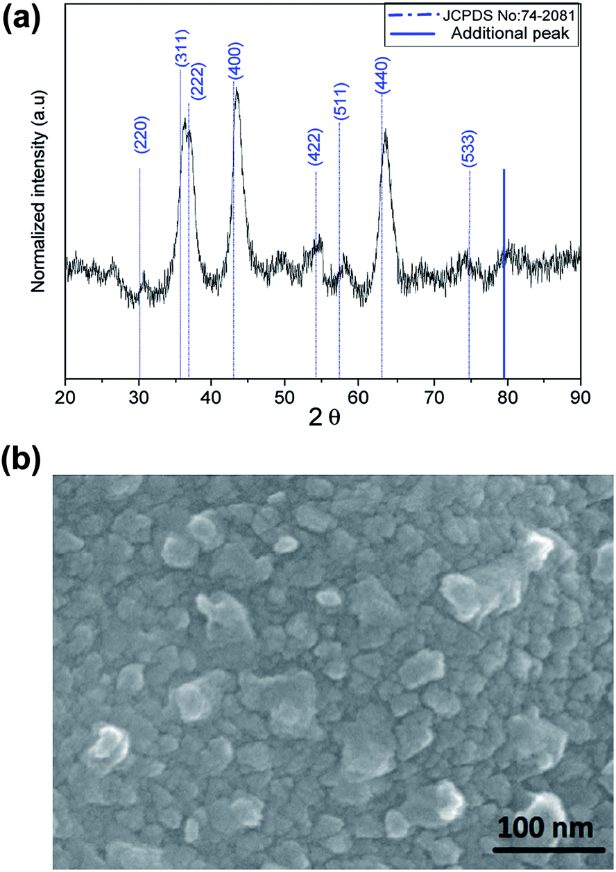
Powder X-ray diffraction (PXRD) pattern of Ni–Al–Fe adsorbent is illustrated in Fig. 1(a). The pattern observed is in correlation with the reported nickel ferrite lattice (JCPDS file no: 742081). Intense peaks around 43.67° and 63.41° corresponding to (400) and (440) lattice planes respectively are in good agreement with the standards (JCPDS file no: 742081).36,37 The crystallite size and interplanar spacing parameters of the adsorbent were evaluated by considering the intense peak around 43.67° corresponding to (400) plane. Inter planar spacing (d) of 2.1 Å and crystallite size of 5.5 nm was evaluated using Bragg's law and Scherer's formula. The occurrence of additional peak around 79°, peak shifting and peak broadening phenomenon indicates the random distribution of a new minor phase in the nickel ferrite lattice. The shift in the peaks observed in the Ni–Al–Fe adsorbent as compared to pure nickel ferrite lattice (JCPDS file no: 742081) is due to the Al3+ ions substitution for Fe3+ ions.36–38 FESEM micrograph studies of synthesized adsorbent particles show near spherical type as shown in Fig. 1(b). The average particle size of the adsorbent particles is around 20–30 nm, suggesting the polycrystalline nature of the synthesized adsorbent. The surface area related parameters of the Ni–Al–Fe adsorbents were recorded using BET surface analyzer. Accordingly, the selective surface area (SSA) of the adsorbent is 111 m2 g−1 with an average pore diameter of 12 nm and a total pore volume of 0.34 cm3 g−1. The (pHPZC) of the Ni–Al–Fe adsorbent was evaluated as 6.73 which is showing better oxyanion adsorption property of the adsorbent in near neutral pH conditions (pH ∼ 7.0).
 |
| | Fig. 1 (a) XRD plot and (b) FESEM image of Ni–Al–Fe adsorbent. | |
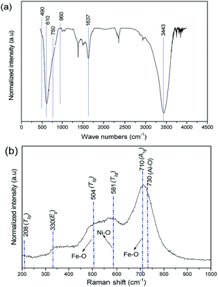
The substitution of Al3+ in place of Fe3+ was analyzed qualitatively using FT-IR, Raman and XPS techniques. The FT-IR spectrum of freshly prepared Ni–Al–Fe particles is illustrated in Fig. 2(a). The vibrational frequency observed around 610 cm−1 is attributed to Fe–O bonds in tetrahedral sites of the crystal lattice. Other bands around 3460 and 1644 cm−1 are corresponding to O–H stretching and bending vibrations of water molecules.39
 |
| | Fig. 2 (a) FT-IR (b) Raman spectra of Ni–Al–Fe adsorbent. | |
Additional bands observed in IR around 490, 750 and 960 cm−1 are the vibrations related to the asymmetric, symmetric and interactive stretching vibrations of Al–O type structures.40 Raman spectrum of freshly prepared Ni–Al–Fe was recorded which shows a broad shoulder as it was reported for the pure nickel ferrite.41 Further comparison of this spectrum with the pure nickel ferrite suggests that the five different Raman active bands can be assigned to the A1g + Eg + 3T2g modes of vibrations as shown in Fig. 2(b). Unlike in pure nickel ferrite, the shift in peaks around 470 and 680 cm−1 corresponding to octahedral and tetrahedral vibrations of Fe(III)–O lattice systems. This blue peak shifting (30 cm−1) behavior in Ni–Al–Fe adsorbent compared to pure nickel ferrite systems deducing the evaluation of a new phase wherein Fe3+ ions are substituted by Al3+ ions.42 Apart from them a small intense band around 730 cm−1 was also observed in Raman spectrum which may be assigned to Al–O type vibration.40 To further verify the presence of Al3+ ions present on the adsorbent near surface region, XPS study was carried out. The wide scan XPS spectrum with their corresponding binding energy (B.E) values of the respective elements is provided in Fig. 3. Besides the B.E values for Ni 2p3/2 (853.7 eV), Fe 2p1/2 (726.3 eV), Fe 2p3/2 (709.8 eV) and O 1s (531 eV), an additional peak was observed for Al 2p (73.4 eV). Thus all spectroscopic tools are confirming the presence of Al3+ ions in the present adsorbent.
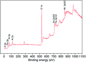 |
| | Fig. 3 XPS wide scan spectrum of Ni–Al–Fe adsorbent. | |
3.2 Adsorption of As(III) and As(V) over Ni–Al–Fe adsorbent at pH 7.0
The adsorption capability of As(III) and As(V) were evaluated using the above Ni–Al–Fe adsorbent. The freshly prepared As(III) and As(V) solutions were used for this study. The adsorbent was agitated for 24 h in these solutions (see experimental section). The adsorption behavior was evaluated using qualitative (FT-IR, Raman), XPS and quantitative (ICP-OES) measurements.
3.2.1 Analysis by FE-SEM images.
The FE-SEM images of as synthesized adsorbent and the arsenic (As) adsorbed samples are shown in Fig. 4. As(III) and As(V) adsorbed Ni–Al–Fe isotherm samples [i.e. pH 7 condition, 24 h reaction] at initial arsenic concentrations (Ci) of 50 ppm were compared with the adsorbent. It was observed that after arsenic adsorption the particles were agglomerated.43–45
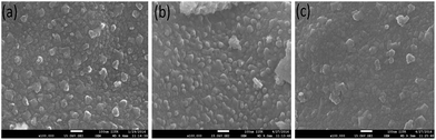 |
| | Fig. 4 FESEM images of (a) Ni–Al–Fe adsorbent and arsenic [(b) As(III) and (c) As(V)] adsorbed samples in pH 7.0. | |
3.2.2 Analysis by vibrational spectroscopy.
The FT-IR spectra of arsenic adsorbed samples were recorded in solid and the corresponding spectra of As(III) and As(V) adsorbed systems in pH 7.0 condition are shown in Fig. 5. A blue shift (20 cm−1) was observed for vibrations corresponding to tetrahedral Fe–O lattice sites additional peaks were also observed around 680–700 cm−1 for As(III) and As(V) adsorbed samples. Raman spectra of As(III) and As(V) adsorbed Ni–Al–Fe samples at pH 7.0 were illustrated in Fig. 6. The corresponding active signals for As(III) and As(V) adsorbed systems were observed between 670 and 770 cm−1 and 800–850 cm−1 region. The peaks around 700 and 800 cm−1 correspond to ν(As–OH) (symmetric and asymmetric) whereas frequencies around 840–850 cm−1 represent the ν(As–O) which are in agreement with the literature.46–53 Apart from these As–O signals a particular blue shift (20–30 cm−1) corresponding to unabsorbed adsorbent vibrations (mainly A1g and T2g modes) is also observed.
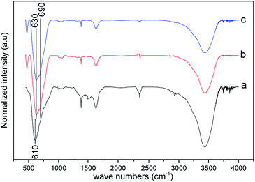 |
| | Fig. 5 FT-IR spectra of Ni–Al–Fe adsorbent (a) and arsenic [As(III) (b) As(V) (c)] adsorbed samples at pH 7.0. | |
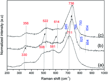 |
| | Fig. 6 Raman spectra of Ni–Al–Fe adsorbent (a) and arsenic [As(III) (b) and As(V) (c)] adsorbed samples in pH 7.0. | |
3.2.3 Analysis by XPS spectroscopy.
XPS analysis has been performed to understand the corresponding oxidation states of arsenic species near the adsorbent surface. The individual spectra of As(3d) for both the arsenic systems at pH 7 were collected.
The corresponding spectra with active binding energies (B.E) are shown in Fig. 7. The corresponding oxidation states and probable species of arsenic present onto the adsorbent were given in Table 1. A clear difference was observed between the binding energies of As 3d peaks for As(III) and As(V) adsorbing systems. As(III) adsorbed system shown peaks around 42.44, 42.93, 43.55 and 44.44 eV, whereas As(V) system displayed peaks around 42.54, 43.34, 43.92, 44.66 eV. The high intense signals found around 43.5 (43 ± 1.0) and 44.5 (44 ± 1.0) eV is assigned As(III)–O and As(V)–O compounds respectively. Thus, in both the systems a change in the oxidation states of arsenic were observed which may be due to redox reactions under normal atmospheric and room temperature conditions.43–45,54,55
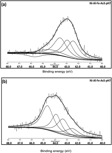 |
| | Fig. 7 Individual As(3d) spectrum arsenic [As(III) (a) and As(V) (b)] adsorbed samples prepared at pH 7.0. | |
Table 1 XPS B.E values of As(III) and As(V) species on Ni–Al–Fe adsorbents in pH 7 systems
| Arsenic – pH |
B.E (eV) |
Oxidation state |
% area |
Arsenic species |
| As(III) – pH 7 |
42.44 |
As(III) |
28.1 |
H2AsO3− |
| 42.93 |
As(III) |
25.6 |
H3AsO3 |
| 43.55 |
As(V) |
30.9 |
HAsO42− |
| 44.44 |
As(V) |
15.3 |
H2AsO4− |
| As(V) – pH 7 |
42.54 |
As(III) |
14.6 |
H2AsO3− |
| 43.34 |
As(III) |
23.9 |
H3AsO3 |
| 43.92 |
As(V) |
23.5 |
HAsO42− |
| 44.66 |
As(V) |
37.9 |
H2AsO4− |
3.3 Quantitative study
The above results clearly suggest that the arsenic adsorption occurs over Ni–Al–Fe adsorbent. In order to understand the quantity and mechanism of adsorption the ICP-OES technique was used.
3.3.1 Adsorption kinetics.
The arsenic adsorption onto the Ni–Al–Fe adsorbent at pH 7 condition was investigated by batch experiments to understand the time dependent arsenic adsorption behavior. The adsorption kinetics plots were illustrated as shown in Fig. 8. It is observed that most of the adsorption phenomenon occurs within the first few minutes of the reaction (around 30 min). The kinetics reaction is saturated over the time period of 360 min in both cases of As(III) and As(V) systems. Different kinetic models, pseudo-first order (PFO) and pseudo second order (PSO) models were used to compare the adsorption kinetics data. The mathematical equations of the PFO and PSO models are| | ln(qe − qt) = ln![[thin space (1/6-em)]](https://www.rsc.org/images/entities/char_2009.gif) qe − k1 × t qe − k1 × t | (2) |
| |  | (3) |
qe: adsorption capacities (mg g−1) on to the adsorbent at equilibrium, qt: adsorption capacities (mg g−1) on to the adsorbent at corresponding time ‘t’ (min), k1 (g mg−1 min−1) and k2 (g mg−1 min−1): related adsorption rate constants.
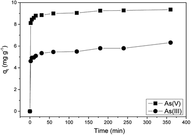 |
| | Fig. 8 Adsorption kinetics study of As(III) and As(V) on Ni–Al–Fe adsorbent. | |
The corresponding rate constants for the PFO and PSO models are listed in Table 2. The corresponding kinetics data, PFO and PSO adsorption kinetics plots were given in the ESI Fig. S1 and Table S2.† PSO model was better suited for both the adsorbates [As(III) and As(V)] implying that the adsorption rate limiting step may be due to the chemical sorption phenomenon involving valence forces by sharing of electrons between Ni–Al–Fe adsorbent and arsenic systems.24 The initial adsorption rate constant (h [mg g−1 min−1] = k2qe2) for As(V) is higher than that of the As(III) species indicating higher selectivity for As(V) adsorption.23
Table 2 Adsorption rate constants for adsorption kinetics obtained from PFO and PSO
| Kinetic models |
Kinetic parameters |
As(III) |
As(V) |
| |
q
e (mg g−1) (experimental) |
6.32 |
9.36 |
| PFO |
q
e (mg g−1) |
1.34 |
0.85 |
|
k
1 (g mg−1 min−1) |
0.004 |
0.01 |
|
R
2
|
0.86 |
0.925 |
| PSO |
q
e (mg g−1) |
6.21 |
9.43 |
|
k
2 (g mg−1 min−1) |
0.03 |
0.07 |
|
R
2
|
0.996 |
0.999 |
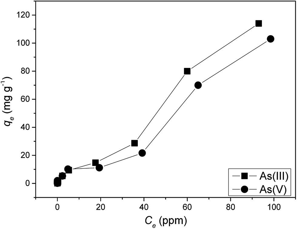
3.3.2 Adsorption isotherms.
The As(III) and As(V) sorption capacities on Ni–Al–Fe ternary oxide adsorbent in different concentration of arsenic solutions were evaluated using adsorption isotherms as given in Fig. 9. Langmuir and Freundlich isotherm models were studied to evaluate the data of adsorption isotherms. The corresponding Langmuir and Freundlich isotherm models are| |  | (4) |
qe (mg g−1): amount of arsenic adsorbed onto the adsorbent at equilibrium condition, qmax (mg g−1): maximum adsorption capacity of the adsorbent evaluated from Langmuir's equation. Ce (mg L−1): arsenic equilibrium concentration remained at the end of the experiment, KL (L mg−1): adsorbent adsorption site's affinity coefficient, KF: adsorption coefficient related to the adsorption intensity of the adsorbent, n: heterogeneity factor related to the adsorption intensity of the adsorbent.
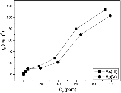 |
| | Fig. 9 Adsorption isotherms of As(III) and As(V) on to Ni–Al–Fe ternary oxide adsorbent. | |
The adsorption constants obtained from the adsorption isotherms are given in Table 3. Maximum arsenic loading abilities (qmax) of 166 [As(III)] and 100 [As(V)] mg g−1 were evaluated using Langmuir equation. Batch adsorption experiments revealed that the maximum adsorption capacities of Ni–Al–Fe adsorbent were around 114 and 103 mg g−1 for As(III) and As(V) systems in around 100 mg L−1 (ppm) arsenic equilibrium concentration (Ce) systems. Coefficients of determination (R2) values reveal that the adsorption of both As(III) and As(V) occurs through Freundlich model. Freundlich isotherm suggests multilayer adsorption on top of the heterogeneous adsorbent surface whereas Langmuir model suggests the monolayer adsorption behavior species on top of the homogenous adsorbent. The corresponding isotherm data and Freundlich isotherm plots were given in the ESI Table S3 and Fig. S2.†
Table 3 Adsorption isotherm related parameters obtained from Langmuir and Freundlich isotherm models
| Isotherm models |
Isotherm parameters |
As(III) |
As(V) |
| |
q
max (mg g−1) (experimental) |
114 |
103 |
| Langmuir |
q
max (mg g−1) |
166 |
100 |
|
K
L(L mg−1) |
0.012 |
0.022 |
|
R
2
|
0.16 |
0.34 |
| Freundlich |
K
F (mg1−n Ln g−1) |
2.48 |
4.61 |
|
n
|
1.28 |
2.04 |
|
R
2
|
0.983 |
0.884 |
3.4 Effect of pH in arsenic adsorption
The effect of concentration in the arsenic adsorption was clearly noted under pH 7.0 medium. It was established earlier that the arsenic adsorption depends on the pH of the medium particularly in the wide range between pH 2 to pH 12 which is attributed to the interaction of different arsenic species with the adsorbent. Thus the effect of arsenic adsorption over the adsorbent was evaluated under different acidic and basic conditions (pH: 2.0, 5.0, 7.0, 9.0 and 12.0). The arsenic adsorbed materials with remaining arsenic content were characterized qualitatively and the filtrate samples were analyzed quantitatively.
The FT-IR spectra (Fig. 10) of the arsenic adsorbed samples at different pH conditions were illustrated. They are nearly similar with the adsorbent except a clear intense signal around 891 cm−1 corresponding to As–O stretching vibrations observed in As(III) adsorbed sample at pH 9 condition.
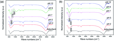 |
| | Fig. 10 FT-IR spectra of (a) As(III) and (b) As(V) adsorbed Ni–Al–Fe samples in different pH conditions. | |
In addition few peaks observed around 700–900 cm−1 band are corresponding to As–OH and As–O vibrations. The higher value in IR signal around 891 cm−1 observed in pH 9 conditions for As(III) systems indicates the strong complexation behavior of As(III) species over other pH range. A similar behavior is also observed for As(V) systems at pH 2 (856 cm−1) and pH 5 (830 cm−1) systems. However, due to the concentration of arsenic on the adsorbent a clear As–OH and As–O vibrational bands are not significantly seen.
The Raman spectra of As(III) and As(V) adsorbed Ni–Al–Fe samples at different pH conditions are given in Fig. 11. In addition to the Ni–Al–Fe adsorbent peaks a weak to intense bands are observed around 680 to 900 cm−1 for As(III) and 760 to 900 cm−1 for As(V) adsorbed samples.
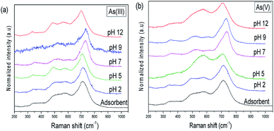 |
| | Fig. 11 Raman spectra of (a) As(III) and (b) As(V) adsorbed Ni–Al–Fe adsorbent particles in different pH conditions. | |
In case of As(III) adsorbed samples obtained at pH 5 and pH 12, a single Raman peak was visible which may be due to the presence of neutral arsenous acid and the complexed [H2AsO3]− species on the adsorbent. In all other pH conditions multiple stretching frequencies for As(III) adsorbed samples were obtained. The exact type of the arsenic binding on the adsorbent is difficult to understand from these values. The Raman spectra in different pH conditions with peak identification related to arsenic complexation were illustrated in the ESI Fig. S3 and S4.† A similar trend is also seen using the Raman spectral analysis of As(V) adsorbed samples.
Like at pH 7, the XPS data of As(III) adsorbed samples at pH 2 to pH 12, indicates the presence of both As(III) and As(V) species as shown in Fig. 12 and detailed in Table 4. However the higher B.E values and intensity of As(V) in As(III) adsorbed sample is slightly higher in pH 2 systems than the peaks observed at pH 12, which indicates a existence of oxidized As(V) form in the acidic medium.43–45
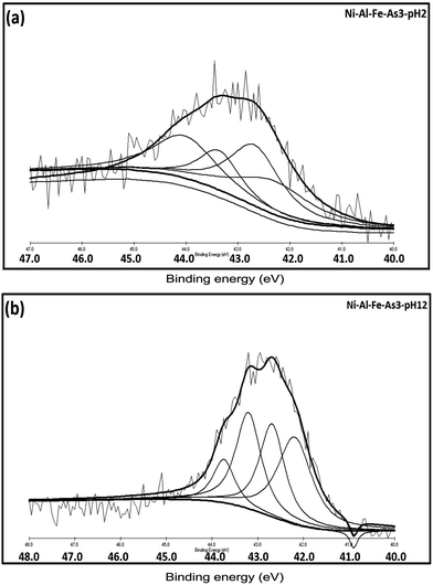 |
| | Fig. 12 Individual As(3d) spectrum of As(III) adsorbed samples prepared at (a) pH 2 and (b) pH 12. | |
Table 4 XPS binding energy values of As(III) species on Ni–Al–Fe adsorbents in different pH systems
| Arsenic – pH |
B.E (eV) |
Oxidation state |
% area |
Arsenic species |
| As(III) – pH 2 |
42.30 |
As(III) |
25.51 |
H3AsO3 |
| 42.60 |
As(III) |
31.54 |
H3AsO3 |
| 43.50 |
As(V) |
16.24 |
HAsO42− |
| 44.03 |
As(V) |
26.69 |
H2AsO4− |
| As(III) – pH 12 |
42.19 |
As(III) |
34.32 |
HAsO32− |
| 42.69 |
As(III) |
26.85 |
HAsO32− |
| 43.20 |
As(III) |
28.01 |
H2AsO3− |
| 43.75 |
As(V) |
10.79 |
HAsO42− |
Further the effective arsenic adsorption on Ni–Al–Fe adsorbent at different pH was studied using ICP-OES and the results are illustrated in the Fig. 13. A gradual decrease and increase (like a second degree polynomial curve) of As(III) adsorption was seen on going from pH 2 to pH 12. The higher As(III) adsorption (∼12 mg g−1) was obtained at pH 12 whereas the least value (∼8 mg g−1) was observed in pH 7. However the highest adsorption (∼18 mg g−1) of As(V) was noted at pH 5 corresponding to the high affinity of [H2ASO4]− binding on the adsorbents. But this trend is not maintained at higher pH conditions which follows a fourth order degree polynomial curve rather with varying crest and trough was obtained. The corresponding pH based studies data was provided in the ESI Table S4.†
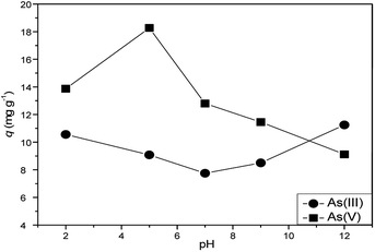 |
| | Fig. 13 Effect of pH on As(III) and As(V) systems adsorption by Ni–Al–Fe adsorbent. | |
3.5 Discussion on arsenic adsorption
A ternary metal oxide nano-adsorbent Ni–Al–Fe was synthesized which was confirmed by PXRD with a peak shift to higher angles that are in correlation with the literature.35 In the first sight, peak broadening in the diffraction pattern indicates the substitution of Al3+ is random in nature.37
This is due to the choice of Al3+ substitution that may occur at octahedral or tetrahedral or even in both sites of Fe3+ ions. The qualitative analysis clearly indicates the substitution of Al3+ ion in replacement of Fe3+ ion sites.
The adsorption of arsenic over Ni–Al–Fe adsorbent at different pH was studied. The Raman spectra of these samples show that the adsorption of arsenic [As(III)] was better at pH 2, pH 7 and pH 9 in which the multiple bands (pH 2 and pH 7) indicates the interaction of H3AsO3 to the adsorbent. The band splitting phenomenon at pH 2 condition may be attributed to As(V) systems (due to the oxidation of As(III)) in acidic conditions. In case of pH 9 both H3AsO3 and [H2AsO3]− might interact with the surface of adsorbent. However, a single band (810 cm−1 at pH 5 and 825 cm−1 at pH 12) corresponding to As–O vibration indicating the presence of H3AsO3, and H2AsO3− species. The similarity in Raman active bands around 825 cm−1 observed in pH 7, pH 9 and pH 12 systems indicates the lack of pH effect on ν(As–O) compounds. This behavior suggests that these Raman active modes are protected by direct complexation behavior onto the adsorbent resulting in the formation of inner sphere surface complex structures of As–O.47
In As(V) adsorbed sample signatory peaks corresponding to the interaction of [H2AsO4]−, [HAsO4]2− and [AsO4]3− with the adsorbent were observed however in other pH conditions a single band corresponding to the highly symmetric structure of arsenic interaction with the adsorbent were noted. The shift in the Raman peaks corresponding to the adsorption indicate both stretching modes of As–OH, As–OZcomplexed (Z = Fe, Ni, Al) and As–Ouncomplexed structures. These active signals are in agreement with the vibrational spectra results of As(V) species on GFH (granular ferric hydroxide) in 820–840 and 880–890 cm−1 bands corresponding to νs(As–O) and νas(As–O).47 Similar to As(III) systems vide infra Raman active bands around 840–850 cm−1 observed in pH 5, pH 7 and pH 9 systems are indicating the lack of pH effect on ν(As–O) compounds. This behavior once again is attributed to direct complexation behavior by forming inner sphere surface complex structures of As–O.47
As mentioned above the nature of arsenic in the arsenic adsorbed samples were analyzed using XPS data. The B.E values indicate in both As(III) and As(V) adsorbed samples fall in the range between 42.19 and 44.44 eV (former: pH 2, pH 7 and pH 12) and 42.54 to 44.66 eV (latter: pH 7). In both the case these values originate from two different oxidation states of arsenic after the adsorption. The different B.E values (Table 1) lower values are assigned to As(III) and the higher values belong to As(V) ion. These multiplet values suggest that the chemical valence of As is increased [As(III) adsorbed samples] irrespective of the pH condition which indicates a redox process occur between adsorbent and adsorbate at this experimental condition (Fig. 7 and 12). The arsenic sorption capability of Ni–Al–Fe adsorbent is detailed above and it suggests that the adsorption capacity of Ni–Al–Fe adsorbent increases with higher equilibrium concentration (Ce) of As(III) and As(V) ions. The percentage of remediation were found varying from 72.2% [As(III)] and 90.0% [As(V)] at lower concentrations (0.1 ppm). This analysis is showing better adsorption behavior of the Ni–Al–Fe adsorbent for As(III) systems in higher concentrations and for As(V) in lower concentrations.
The arsenic(III) adsorption decreases initially upon increasing pH value up to 7.0 and increases subsequently at high pH conditions with a maximum adsorption value of 12 mg g−1 at pH 12. This increase in the adsorption is also evident through an intense Raman signal at 825 cm−1 signifying the better complexation behavior of As(III). However, the adsorption of As(V) over the adsorbent increases up to pH 5 (18 mg g−1) and later decreases upon increasing the pH medium. The high pHPZC value of adsorbent around 6.73 is also in supporting the high As(V) adsorption behavior at pH 5.0 system. The higher value indicating the positive charged surface at pH 5.0 conditions so that it can absorb [H2ASO4]− anions on the adsorbent, while the decrement in the adsorption for As(V) systems at higher pH systems (i.e. pH 7.0, 9.0 and 12.0) may be because of repulsion between the negatively charged adsorbent and other arsenic anions present in the system (i.e. [HAsO4]2−, [AsO4]3−). A comparison with the adsorption capacity and arsenic equilibrium concentration against the adsorbents at pH 7 were shown in Table 5.
Table 5 As(III) and As(V) adsorption capacities of different metal oxide adsorbents at pH 7.0
| Adsorbent |
As(III) qe (mg g−1) |
As(III) Co [ppm] |
As(V) qe (mg g−1) |
As(V) Co [ppm] |
Reference |
|
Calculated based on the data provided in ref. 44.
|
| Feo (NZVI)-adsorbent |
3.5 |
0–4.5a |
N/A |
N/A |
44
|
| α-Fe2O3 |
10 |
0–190 |
N/A |
N/A |
27
|
| Al-doped α-Fe2O3 |
40 |
0–175 |
N/A |
N/A |
27
|
| Fe3O4 |
44 |
0–70 |
17 |
0–50 |
13
|
| NiFe2O4 |
168 |
0–1000 |
90 |
0–1000 |
23
|
|
Ni-Al-Fe
|
114
|
0–150
|
103
|
0–150
|
This work
|
The adsorption isotherms indicate multilayer adsorption phenomena vide infra and the kinetics study confirms the chemisorption (PSO) based rate limiting adsorption phenomenon. As mentioned earlier by Li et al. replacement of iron(III) by aluminum(III) ion increases the arsenic adsorption due to the increase in the surface hydroxyl groups.27,29 In a similar manner in the present study the substitution of iron(III) by aluminum(III) shows higher adsorption capacity of As(III) (114 mg g−1) which is slightly higher than NiFe2O4 (∼105 mg g−1) adsorbent at equilibrium concentrations (Ce) of 100 ppm (mg L−1). The present Ni–Al–Fe adsorbent indicates the quantity of adsorption is comparable to that adsorption to earlier reported by Choi and co-workers.44 However the adsorption of As(V) over the adsorbent is smaller (∼103 mg g−1) than the As(III) but this value is much higher than the NiFeO4 (∼50 mg g−1) at equilibrium concentrations (Ce) of 100 ppm.23
4. Conclusion
A ternary metal oxide nano-adsorbent containing aluminum substituted nickel ferrite (Ni–Al–Fe) is evaluated for the arsenic adsorption at different time, concentration and pH conditions. The qualitative analysis using Raman, FT-IR and XPS techniques suggests the adsorption of arsenic over the adsorbent. The pH independent Raman spectra for As(III) and As(V) adsorbed systems indicate the formation of inner sphere complex onto the adsorbent. Adsorption kinetics revealed that both As(III) and As(V) systems show PSO model suggesting the chemisorption phenomenon. As(III) and As(V) systems were observed with multilayer adsorption behavior on top of a heterogeneous surface by Freundlich isotherm model. This is supported by XPS spectra which suggest the possible redox induced adsorption property between adsorbate and adsorbent at different pH conditions. The final residual arsenic values (Ce) of 5.9 and 9.9 ppb for low initial concentrations (C0) (100 and 500 ppb) that falls below WHO standard value of the 10 ppb. This suggests that the current adsorbent may be a potential candidate which can be used for the separation of As(V) contaminants in water at pH 7.0. Further study to understand redox induced adsorption property and surface complexation behavior in detail is under progress using X-ray absorption spectroscopy (XAS) tools.
Acknowledgements
Y. K. Penke thank Indian Institute of Technology Kanpur (IIT Kanpur) for providing doctoral research fellowship. The authors thank Mr M. Siva Kumar, ACMS, IIT Kanpur in helping in different characterisation techniques. The authors would also like to thank Department of Science and Technology (DST), Government of India for providing funding to carry on this present research work.
References
- D. Mohan and C. U. Pittman, J. Hazard. Mater., 2007, 142, 1–53 CrossRef CAS PubMed.
- M. L. Pierce and C. B. Moore, Water Res., 1982, 16, 1247–1253 CrossRef CAS.
- A. H. Smith, E. O. Lingas and M. Rahman, Bull. W. H. O., 2000, 78, 1093–1103 CAS.
- H. G. Gorchev and G. Ozolins, WHO Chron., 2011, 38, 104–108 Search PubMed.
- E. O. Kartinen and C. J. Martin, Desalination, 1995, 103, 79–88 CrossRef CAS.
- F. Fu and Q. Wang, J. Environ. Manage., 2011, 92, 407–418 CrossRef CAS PubMed.
- J. Wang, W. Xu, L. Chen, X. Huang and J. Liu, Chem. Eng. J., 2014, 251, 25–34 CrossRef CAS.
- T. A. Vu, G. H. Le, C. D. Dao, L. Q. Dang, K. T. Nguyen, Q. K. Nguyen, P. T. Dang, H. T. K. Tran, Q. T. Duong, T. V. Nguyen and G. D. Lee, RSC Adv., 2015, 5, 5261–5268 RSC.
- D. Setyono and S. Valiyaveettil, ACS Sustainable Chem. Eng., 2014, 2, 2722–2729 CrossRef CAS.
- S. Vadahanambi, S. H. Lee, W. J. Kim and I. K. Oh, Environ. Sci. Technol., 2013, 47, 10510–10517 CAS.
- P. Z. Ray and H. J. Shipley, RSC Adv., 2015, 5, 29885–29907 RSC.
- C. T. Yavuz, J. T. Mayo, W. W. Yu, A. Prakash, J. C. Falkner, S. Yean, L. Cong, H. J. Shipley, A. Kan and M. Tomson, Science., 2006, 314, 964–968 CrossRef PubMed.
- L. Feng, M. Cao, X. Ma, Y. Zhu and C. Hu, J. Hazard. Mater., 2012, 217–218, 439–446 CrossRef CAS PubMed.
- S. Lin, D. Lu and Z. Liu, Chem. Eng. J., 2012, 211–212, 46–52 CrossRef CAS.
- C. Han, H. Pu, H. Li, L. Deng, S. Huang, S. He and Y. Luo, J. Hazard. Mater., 2013, 254–255, 301–309 CrossRef CAS PubMed.
- M. Anderson, J. F. Ferguson and J. Gavis, J. Colloid Interface Sci., 1976, 54, 391–399 CrossRef CAS.
- C. A. Martinson and K. J. Reddy, J. Colloid Interface Sci., 2009, 336, 406–411 CrossRef CAS PubMed.
- M. Zhu, K. W. Paul, J. D. Kubicki and D. L. Sparks, Environ. Sci. Technol., 2009, 43, 6655–6661 CrossRef CAS PubMed.
- S. Purwajanti, L. Zhou, Y. Ahmad Nor, J. Zhang, H. Zhang, X. Huang and C. Yu, ACS Appl. Mater. Interfaces, 2015, 7, 21278–21286 CAS.
- S. Kong, Y. Wang, Q. Hu and A. K. Olusegun, Colloids Surf., A, 2014, 457, 220–227 CrossRef CAS.
- B. Chen, Z. Zhu, Y. Guo, Y. Qiu and J. Zhao, J. Colloid Interface Sci., 2013, 398, 142–151 CrossRef CAS PubMed.
- G. Zhang, Z. Ren, X. Zhang and J. Chen, Water Res., 2013, 47, 4022–4031 CrossRef CAS PubMed.
- S. Liu, S. Kang, G. Wang, H. Zhao and W. Cai, J. Colloid Interface Sci., 2015, 458, 94–102 CrossRef CAS PubMed.
- W. Tang, Y. Su, Q. Li, S. Gao and J. K. Shang, Water Res., 2013, 47, 3624–3634 CrossRef CAS PubMed.
- Y. J. Tu, C. F. You, C. K. Chang, S. L. Wang and T. S. Chan, Chem. Eng. J., 2012, 198–199, 440–448 CrossRef CAS.
- S. Zhang, H. Niu, Y. Cai, X. Zhao and Y. Shi, Chem. Eng. J., 2010, 158, 599–607 CrossRef CAS.
- R. Li, Q. Li, S. Gao and J. K. Shang, J. Am. Ceram. Soc., 2011, 94, 584–591 CrossRef CAS.
- A. Adra, G. Morin, G. Ona-nguema, N. Menguy, F. Maillot, C. Casiot, O. Bruneel, S. Lebrun, F. Juillot and J. Brest, Environ. Sci. Technol., 2013, 47, 12784–12792 CrossRef CAS PubMed.
- M. A. Malana, R. B. Qureshi and M. N. Ashiq, Chem. Eng. J., 2011, 172, 721–727 CrossRef CAS.
- T. Wang, W. Yang, T. Song, C. Li, L. Zhang, H. Wang and L. Chai, RSC Adv., 2015, 5, 50011–50018 RSC.
- W. Tang, Y. Su, Q. Li, S. Gao and J. K. Shang, J. Mater. Chem. A, 2013, 1, 830–836 CAS.
- A. Dhillon, M. Nair, S. K. Bhargava and D. Kumar, J. Colloid Interface Sci., 2015, 457, 289–297 CrossRef CAS PubMed.
- Y. Yu, L. Yu and J. P. Chen, Chem. Eng. J., 2015, 262, 839–846 CrossRef CAS.
- X. Wu, Y. Zhang, X. Dou, B. Zhao and M. Yang, Chem. Eng. J., 2013, 223, 364–370 CrossRef CAS.
- K. Biswas, K. Gupta, A. Goswami and U. C. Ghosh, Desalination, 2010, 255, 44–51 CrossRef CAS.
- K. Maaz, S. Karim, A. Mumtaz, S. K. Hasanain, J. Liu and J. L. Duan, J. Magn. Magn. Mater., 2009, 321, 1838–1842 CrossRef CAS.
- A. T. Raghavender, D. Pajic, K. Zadro, T. Milekovic, P. Venkateshwar Rao, K. M. Jadhav and D. Ravinder, J. Magn. Magn. Mater., 2007, 316, 1–7 CrossRef CAS.
- S. Maensiri, C. Masingboon, B. Boonchom and S. A. Seraphin, Scr. Mater., 2007, 56, 797–800 CrossRef CAS.
- A. F. D. Lehlooh, J. Amighian and S. H. Mahmood, Hyperfine Interact., 2008, 183, 193–198 CrossRef CAS.
- A. A. Sattar, H. M. Sayed, K. M. Shokrofy and M. M. Tabey, J. Appl. Sci., 2005, 5, 162–168 CrossRef.
- A. Ahlawat and V. G. Sathe, J. Raman Spectrosc., 2011, 42, 1087–1094 CrossRef CAS.
- J. M. Saniger, Mater. Lett., 1995, 22, 109–113 Search PubMed.
- Z. Cheng, F. Fu, D. D. Dionysiou and B. Tang, Water Res., 2016, 96, 22–31 Search PubMed.
- S. R. Kanel, B. Manning, L. Charlet and H. Choi, Environ. Sci. Technol., 2005, 39, 1291–1298 Search PubMed.
- S. R. Kanel, J. M. Greneche and H. Choi, Environ. Sci. Technol., 2006, 40, 2045–2050 Search PubMed.
- K. Müller, V. S. T. Ciminelli, M. S. S. Dantas and S. A. Willscher, Water Res., 2010, 44, 5660–5672 CrossRef PubMed.
- S. Goldberg and C. T. Johnston, J. Colloid Interface Sci., 2001, 234, 204–216 CrossRef CAS PubMed.
- F. K. Vansant, B. J. Van Der Veken and H. O. Desseyn, J. Mol. Struct., 1973, 15, 425–437 CrossRef CAS.
- F. K. Vansant and B. J. Van Der Veken, J. Mol. Struct., 1973, 15, 439–444 CrossRef CAS.
- X. H. Guan, J. Wang and C. C. Chusuei, J. Hazard. Mater., 2008, 156, 178–185 CrossRef CAS PubMed.
- W. Mitchell, S. Goldberg and H. A. Al-Abadleh, J. Colloid Interface Sci., 2011, 358, 534–540 CrossRef CAS PubMed.
- S. C. Myneni, S. J. Traina, G. A. Waychunas and T. J. Logan, Geochim. Cosmochim. Acta, 1998, 62, 3285–3300 CrossRef CAS.
- S. J. Parikh, B. J. Lafferty and D. L. Sparks, J. Colloid Interface Sci., 2008, 320, 177–185 CrossRef CAS PubMed.
- S. R. Chowdhury, E. K. Yanful and A. R. Pratt, J. Hazard. Mater., 2012, 235–236, 246–256 CrossRef CAS PubMed.
- Y. Wang, W. Liu, T. Wang and J. Ni, J. Colloid Interface Sci., 2015, 440, 253–262 CrossRef CAS PubMed.
Footnote |
| † Electronic supplementary information (ESI) available: Information about adsorbent synthesis, Raman spectra (individual peak identification), quantitative study related plots and tables and arsenic stretching vibrations from literature. See DOI: 10.1039/c6ra06332b |
|
| This journal is © The Royal Society of Chemistry 2016 |
Click here to see how this site uses Cookies. View our privacy policy here. 
 Open Access Article
 This Open Access Article is licensed under a Creative Commons Attribution-Non Commercial 3.0 Unported Licence