Retracted Article: Enhanced electrocatalytic activity and durability of highly monodisperse Pt@PPy–PANI nanocomposites as a novel catalyst for the electro-oxidation of methanol

Özlem Karatepe , Yunus Yıldız, Handan Pamuk, Sinan Eris, Zeynep Dasdelen and Fatih Sen*
Sen Research Group, Biochemistry Department, Faculty of Arts and Science, Dumlupınar University, EvliyaÇelebi Campus, 43100 Kütahya, Turkey. E-mail: fatih.sen@dpu.edu.tr; Fax: +90 274 265 20 56; Tel: +90 274 265 20 31 37 02

Received 8th March 2016 , Accepted 18th May 2016

First published on 19th May 2016


Abstract

Highly monodisperse Pt nanocomposites (Pt@PPy–PANI NPs) supported on polypyrrole (PPy)–polyaniline (PANI) have been successfully synthesized for the first time by a simple one-pot process, which involves the simultaneous reduction of the conducting polypyrrole (PPy)–polyaniline (PANI) and Pt precursors using DMAB (dimethylamine borane) as a reductant under ultrasonic conditions. Pt@PPy–PANI NPs have been characterized by X-ray diffraction (XRD), transmission electron microscopy (TEM), and X-ray photoelectron spectroscopy (XPS). All the results show that highly crystalline and stable colloidal Pt@PPy–PANI NPs have been formed as one of the most active and long-lived catalysts with superior reusability performance for the electro-oxidation of methanol at room temperature. Compared to PPy or PANI supported Pt nanoparticles, Pt@PPy–PANI NPs exhibit extraordinary electrocatalytic activity and stability toward the electro-oxidation of methanol, showing their potential use as a new electrode material for direct methanol fuel cells (DMFCs). It should be primarily attributed to the PPy–PANI, which not only provided larger surface area and flaws for the deposition of Pt nanoparticles, but also the adsorption of more methanol molecules for further oxidation.

Introduction

Fuel cell technology is of tremendous interest, because of both energy and environmental considerations.1–11 Because of the continuous consumption of fossil fuels and the ever-increasing environmental issues, there has been increasing involvement in the development of fuel cell systems, especially direct alcohol fuel cells (DAFCs). DAFCs have captivated increasing attention as powerful and clean electrochemical energy converters for electric vehicles and portable electronic devices.12–15 Recently, direct methanol fuel cells (DMFCs) have been actively followed as a clean power source for portable electronic devices due to their high-energy conversion efficiency, ambient operating conditions, the systems' ease-of-use, and eco-friendliness.16–22 However, the performance of DMFCs is still limited by the lower levels of electrocatalytic activity and poor durability. With this in mind, remarkable research efforts have centred upon the development of these systems with the purpose of producing materials with higher levels of electrocatalytic activity and stability. To date, Pt-based electrocatalysts are regarded as the most popular and effective anodic electrocatalysts for DMFCs due to the very high electrocatalytic activities of these materials.23–25 However, the poisoning by CO-like intermediates and the high price of Pt hamper their extensive use in DMFCs in the commercial market.26–30 For this purpose, Pt nanoparticles (NPs) have been dispersed on high surface area supporting materials.31,32 Until now, carbon-based materials, such as carbon nanotubes (CNTs), carbon black, carbon nanofibers, etc., have been generally used as supporting materials for Pt catalysts.33–36 Additionally, conducting polymers are also well-recognized supporting materials for Pt catalysts owing to their easy operation and notable electrical properties. In the midst of these materials, polypyrrole (PPy) and polyaniline have been regarded as the most promising electrode supporting materials because of its easy synthesis, low cost, high surface area and relatively high conductivity.37–42 Moreover, these conducting polymers have been used as supporting materials for metal nanocatalysts in lots of potential applications.43–45 On the other hand, metal nanoparticles incorporated into conducting polymers are also known to enhance the conductivity of the polymers.46–48 Interestingly, it can be thought that one of the activation processes to improve the electrochemical activity of catalysts may be combination of PPy and PANI as the catalyst support. Herein, using DMAB (dimethylamino borane) as reductant was extended to prepare Pt nanoparticles loaded composite conductive polymers materials. It was hoped to combine the advantages of PPy–PANI composites and Pt nanoparticles by using this simple, green but powerful technique to make a new kind of polymer composite materials for the catalyst of fuel cell. Up to now, several methods have been used to prepare Pt-based catalysts such as impregnation, colloidal, microemulsion, seed mediated growth method etc. In those methods, generally, a suitable reducing agent, such as NaBH4, ethylene glycol, 1,2-hexadecanediol, N2H4, formic acid, formaldehyde, borane-tert-butylamine, superhydride, sodium citrate, and N,N-dimethylformamide etc. have been used for the synthesis of nanomaterials.49–57 Of particular interest, DMAB is really a model substrate since it is a nontoxic, crystalline solid at room temperature that is stable in air and water and is environmentally benign.3 In addition, it can be handled at room temperature and contains a moderate hydrogen content (3.5 wt%) that it is used for the first time as a reducing agent for nanoparticle preparation. This offers the possibility of making different noble-metal nanoparticles loaded polymer composite and also provides a new polymer nanocomposite material for DMFC application. The morphology and structure of Pt nanoparticles loaded polymer composite materials (Pt@PPy–PANI NPs) were systematically characterized by transmission electron microscopy (TEM), X-ray photoelectron spectroscopy (XPS) and X-ray diffraction (XRD). Further electrochemical experiments revealed excellent electrocatalytic activity and stability of the Pt@PPy–PANI NPs toward methanol oxidation reaction compared to Pt@PPy NPs and Pt@PANI NPs, showing potential applications of Pt@PPy–PANI NPs in the direct alcohol fuel cells.

Material and methods

The preparation of Pt@PANI, Pt@PPy and Pt@PPy–PANI NPs

Our novel route to prepare Pt@PPy–PANI nanocomposites is as follows: 20.0 mg polypyrrole was dissolved in 25 mL water by ultrasonic treatment for 1 h, and then 20 mg polyaniline and 24 mL water were added while stirring for another 1 h. After that, 2 mL 0.01 M PtCl4 and 148 mg dimethylamine borane complex were added into the above solution under ultrasonic conditions. The solution was kept stirring in reflux during at temperature of 90 °C for 12 h. The collapsed Pt@PPy–PANI NPs were separated by centrifugation. Finally, the prepared nanocatalyst was completely washed with ethanol and pure water. Then solid sample was dried in a vacuum at room temperature. For comparison, Pt nanoparticles attached on polypyrrole or polyaniline were also prepared by the same procedure as described above and the composites were denoted as Pt@PPy NPs and Pt@PANI NPs, respectively.

Fabrication of Pt@PANI NPs, Pt@PPy NPs and Pt@PPy–PANI NPs working electrodes

The Pt@PANI NPs working electrode was manufactured as follows; 6 mg Pt@PANI NPs composites were well mixed in 1 mL DMF and 10 μL 5% Nafion by ultrasonic bath to form a homogeneous solution. After, 5 μL of the resulting solution was dropped by pipette onto the surface of glassy carbon disk (diameter 3 mm) which had been polished with alumina and rinsed with pure water. Next, electrode was dried at room temperature. The other two electrodes, Pt@PPy NPs and Pt@PPy–PANI NPs working electrodes, were prepared with the same procedure described above.

Results and discussion

The characterization of morphology and structure of Pt@PPy–PANI NPs composites

Pt@PPy–PANI NPs has been prepared by sonochemical reduction method as given experimental section and their preliminary characterization was performed by FTIR, TEM, HRTEM, XRD, XPS and SEM methods.

The FTIR spectrum and detail explanation of PANI, PPy, PANI–PPy composite are shown in ESI (Fig. S1).

Crystalline structure of the as-prepared Pt@PPy–PANI NPs nanocomposites was characterized by XRD, and the typical spectrum is shown in Fig. 1 together with the spectra of as-prepared Pt@PPy NPs and as-prepared Pt@PANI NPs. The diffraction peak observed at 2θ of 39.82°, 46.04°, 67.61° and 81.35° are attributed to Pt(111), Pt(200), Pt(220), and Pt(311) characteristic diffraction peaks, respectively, which means that Pt forms a face-centered cubic (fcc) crystal structure in all prepared catalyst. The Pt(220) peak was used to calculate the particle size of Pt according to the Scherrer formula,35 and the average particle size of Pt nanoparticles was found to be 3.539, 3.969 and 3.176 nm for Pt@PPy NPs, Pt@PANI NPs and Pt@PPy–PANI NPs, respectively (Table S1).


image file: c6ra06210e-f1.tif
Fig. 1 XRD patterns of Pt@PPy NPs, Pt@PANI NPs and Pt@PPy–PANI NPs.

The morphology and structure of the synthesized catalysts were also characterized by TEM.

Plenty of Pt nanoparticles responded as black dots in the images of catalyst, and indicated in Fig. 2. It was seen that the PtNPs dispersed uniformly comparably small part on PPy–PANI support. The PtNPs has been fairly dispersed truly in surface of support material. Particle size of the Pt@PPy–PANI NPs was found as 3.326 nm in HRTEM (Table S1). The representative atomic lattice fringes get by HRTEM for Pt@PPy–PANI NPs were also shown in Fig. 2. In consequence of these fringes, Pt(111) and (200) planes were observed within spacing of 0.227 and 0.196 nm on the prepared Pt@PPy–PANI NPs, respectively, which is very close to nominal Pt(111) and (200) spacing of 0.228 and 0.198 nm, respectively.35


image file: c6ra06210e-f2.tif
Fig. 2 TEM images of Pt@PPy–PANI NPs polymer composites with particle size histogram.

X-ray photoelectron spectroscopy (XPS) was employed to explore the nanocatalyst and oxidation states of the as prepared samples. Fig. 3 shows the XPS survey spectra of Pt@PPy–PANI NPs, where four elements including C, O, N and Pt were detected. Fig. 3 XPS images (A) Pt@Ppy NPs, (B) Pt@PANI NPs and (C) Pt@PPy–PANI NPs. The existence of C, N and part of O can be ascribed to the unremoved PPy and PANI molecules. Gaussian–Lorentzian method and subtraction of the Shirley-shaped background, the fitting of XPS peak was carried out. The oxidation states of Pt were studied by XPS following the Pt 4f transitions, respectively. The Pt 4f spectral profiles for Pt@PPy–PANI NPs catalysts are included in Fig. 3, where the Pt 4f region displayed spin–orbital splitting of the 4f7/2 and 4f5/2 states. The C 1s core-line has a binding energy of 284.6 eV. The Pt 4f spectra of the catalysts are composed of two pairs of doublets which are illustrated in Fig. 3. The most intense doublet is observed at about 71.1–71.5 and 74.3–74.6 eV and is assigned to zero-valent platinum. The second doublet is seen at about 74.3–74.6 and 77.6–77.9 eV and is attributed to unreduced surface Pt(IV) range, such as PtO2 and/or Pt(OH)4. In Fig. 3, the maximum energies of the main bands for all samples appeared at 74.3 eV and 74.6 eV, suggesting the presence of metallic Pt, and the binding energy values for metallic Pt were in agreement with published data. Table S2 also summarizes the Pt(0) to Pt(IV) ratio which was calculated from the relative peak area of the Pt(0) to Pt(IV) species. The zero vallents Pt(0) and Pt(IV) ratio is an indication of the metallic character of the prepared catalysts.


image file: c6ra06210e-f3.tif
Fig. 3 The Pt 4f XPS spectra of Pt@PPy NPs (a), Pt@PANI NPs (b) and Pt@PPy–PANI NPs (c).

C 1s, O 1s N 1s XPS spectrum has also been performed for chemical state investigation as shown in Fig. S2. The major feature of the core level spectrum of C 1s is a peak at around 284.6 eV, characteristic of the neutral carbon species. This peak is also ascribed to the carbon backbone of the polypyrrole and polyaniline. Another two components with binding energies at around 285.6 and 286.7 eV are associated with the presence of C–N and C–OH or C[double bond, length as m-dash]O may come from adsorbed oxygenated species and environment. The O 1s core level peak is as expected, located at 531 eV. It can be resolved into three components, namely, as terminal oxygen ([double bond, length as m-dash]O), the linkage oxygen (–O–), and the peak fitted around 532 eV which is assumed to come from humidity in ambience. The peak at around 399.0 eV is attributed to the N 1s which comes from polypyrrole and polyaniline. The spectrum deconvoluted into two major component peaks centred at 399.6 and 400.5 eV which are characteristic of pyrrolylium nitrogen's (–NH structure) and the positively charged nitrogen (–NH+ (polaron)).

Fig. 4a–c show the FESEM micrograph of Pt@PPy NPs, Pt@PANI NPs and Pt@PPy–PANI NPs catalysts that have similar microscopic structures. The figure was taken randomly from the surface of the electrode. Monodisperse Pt NPs have been homogenous dispersed on the surface of the polymer composites and have average diameter of ∼200 nm. As for Pt NPs, PANI and PPy network was entangled to prepare Pt@PPy–PANI NPs, which was evenly distributed and showed an average diameter of 90 nm. This nice distribution may be due to the high surface area of PPy–PANI, which impregnated the catalyst and improved the catalytic activity. Fig. S3 also shows the comparison of the EDAX elemental composition data for all prepared catalysts. It can be seen that the morphology of the PPy–PANI composite are distinctly different from that of the homopolymers. Moreover, as it can be seen from Fig. S3, Pt@PPy–PANI has larger Pt% value compared to the other prepared catalysts.


image file: c6ra06210e-f4.tif
Fig. 4 The SEM images of Pt@PPy NPs (a), Pt@PANI NPs (b) and Pt@PPy–PANI NPs (c).

As addressed above, Pt@PANI NPs, Pt@PPy NPs and Pt@PPy–PANI NPs nanocomposite materials have been achieved by a one-step procedure in which PANI, PPy and Pt ions were both reduced directly with DMAB. Inspired by the attractive structure, it was evaluated as a catalyst for the electro-oxidation of alcohols. The cyclic voltammograms (CV) for all catalysts, in 0.5 M H2SO4 at room temperature, are quite similar and the CV experiments were performed with potentials between −0.2/0.8 V (vs. Ag/AgCl) and a scan rate of 50 mV s−1 at room temperature as shown in Fig. S4. Typical peaks corresponding to hydrogen desorption and adsorption on Pt occurs, which is a useful for evaluating the electrochemically active surface area (ECSA) of Pt catalyst. The electrochemical surface area (ECSA) of the catalyst in m2 g−1 could be determined from the following formula (1);8

 
image file: c6ra06210e-t1.tif(1)
where Q is the electric charge for the hydrogen desorption region, and assuming a correspondence value of 0.21 mC cm−2 Pt that indicates the charge required to oxidize a monolayer of H2 on platinum. The specific surface areas (SSA) of the catalysts were calculated using Sauter formula (2):
 
image file: c6ra06210e-t2.tif(2)
where d is the mean Pt crystalline size in Å (from the XRD results) and ρ is the density of Pt metal (21.4 g cm−2).48

ECSA, SSA, platinum utilization efficiency (% Pt utility = (ECSA/SSA) × 100), and roughness factor Rf (m2 g−1 Pt per cm2) [ECSA/Ag, where Ag is the geometric area (cm2)] are shown in Table S3 (3).3a,4,8

 
image file: c6ra06210e-t3.tif(3)

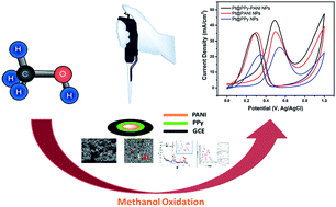
Table S3 summarizes the SSA, ECSA, Rf and % Pt utility for the prepared catalysts. It can be clearly seen that because Pt@PPy–PANI NPs has the highest SSA, ECSA, roughness factor and platinum utility%, its electrocatalytic activity towards methanol oxidation is much higher compared to the Pt@PPy NPs or Pt@PANI NPs as shown in Fig. 5.


image file: c6ra06210e-f5.tif
Fig. 5 Cyclic voltammograms of Pt@PPy NPs, Pt@PANI NPs and Pt@PPy–PANI NPs in nitrogen saturated solution of 0.5 M H2SO4 containing 0.5 M CH3OH at a scan rate of 50 mV s−1.

The polymer electroactivity of the PANI and PPy demonstrated with faradic processes in acidic media. Thus, there is major effectiveness on the catalytic reaction of the monodisperse Pt NPs. Higher catalytically active areas and flaws can be formed in the presence of PPy–PANI composites chains. Because these active areas result in the adsorption of more alcohol for further oxidation on the surface of the Pt@PPy–PANI catalyst for methanol oxidation. As can be seen, first, methanol can be dissociated spontaneously at Pt electrodes to produce CO and other species, which block Pt surface sites and suppress the electro-oxidation of methanol at potentials lower than 0.6 V. It is envisaged that PANI and PPy may play important roles on inhibition of the poisoning effect of CO on Pt particles. Firstly, the enhanced catalytic effect for the oxidation of methanol for Pt@PPy–PANI electrode is attributed to the presence of adsorbed water or hydroxide in the PPy–PANI surface. Adsorbed water or hydroxide facilitates the oxidation of CO that is bound to Pt particles at a lower potential. The adsorbed hydroxyl radicals also activate the oxidation of CO in the Pt surface. Further, the matrix of PPy–PANI is expected to (i) hinder the formation of strongly absorbed poisons, (ii) catalyze the oxidation of strongly adsorbed poisons, and (iii) catalyze the oxidation of weekly adsorbed poisons. Hence, Pt@PPy–PANI electrodes have catalytic effects to promote the oxidation of CO on Pt surface

Pt + CH3OH → Pt–(CH3OH)ads

Pt–(CH3OH)ads → Pt–(CH2OH)ads + H+ + e

Pt–(CH2OH)ads + Pt → Pt2–(CHOH)ads + H+ + e

Pt2–(CHOH)ads + Pt → Pt3–(COH)ads + H+ + e

Pt–(COH)ads → Pt–(CO)ads + H+ + e

Pt + H2O → Pt–(H2O)ads

Pt–(H2O)ads → Pt–(OH)ads + H+ + e

Pt3–(COH)ads + Pt–(H2O ya da OH)ads → 4Pt + CO2 + 3H+ + 3e

Pt–(H2O)ads + Pt–(CO)ads → 2Pt + CO2 + 2H+ + 2e

Pt–(OH)ads + Pt–(CO)ads → 2Pt + CO2 + H+ + e

Besides, for the durability measurements, both chronoamperometry and long-term life time test have been performed by comparing currents between 1st and 1000th cycle by using cyclic voltammetry. As shown in Fig. S5, PPy–PANI supported Pt nanoparticles have higher catalytic activity and durability even after 1000th cycle compared to the others because of unique π-conjugated structures, which lead to good environmental stability, high electrical and proton conductivity in acidic environments, and unique redox properties of PPy–PANI. Fig. 6 shows the chronoamperometric curves obtained at 0.50 V which is the highest value for anodic peak current, the prepared catalysts have been electrolyzed in the presence of same solution at the potential of 0.50 V. The chronoamperometry curves show a sudden change in the current density corresponding to oxidation of methanol. From Fig. 6 and S5, it can be said that PPy–PANI supported Pt nanoparticles have higher catalytic activity and durability compared to the others when we look at the current after 3600 s.


image file: c6ra06210e-f6.tif
Fig. 6 Chronoamperometric curves for of Pt@PPy NPs, Pt@PANI NPs and Pt@PPy–PANI NPs in nitrogen saturated solution of 0.5 M H2SO4 containing 0.5 M CH3OH at a scan rate of 50 mV s−1 at a fixed potential of 0.5 V (vs. Ag/AgCl).

Besides, the cyclic voltammograms of Pt@PPy–PANI on methanol oxidation have also been examined at different scan rates and switching potentials as shown in Fig. S6 and S7. A decrease of upper limit potential cycling causes: (I) a slight augmentation of current of the oxidation peak a on the second positive sweep; (II) a positive shift of the potential of peaks a, b and c compared to d; (III) the peak currents ratio of two peaks a and d approaches to the unity. These may be explained by the preventing of PtO formation by lowering the upper limit potential cycling and consequently maintaining the electrode surface relatively clean.

As a result, since the facile synthesis, perfect properties and low cost of Pt@PPy–PANI nanocatalysts, they could be used fairly widespread in PEMFC and other areas.

Conclusions

In conclusion, we have demonstrated the fabrication of PPy, PANI and PPy–PANI composite supported Pt electrocatalysts by a clean and efficient route in which DMAB was chosen as the reducing agent. With this environment-friendly approach, uniformly dispersed Pt nanoparticles attachment on PPy–PANI composite were achieved in one step via sonochemical reduction of Pt-containing precursor. The Pt@PPy–PANI NPs composite exhibited an extraordinary performance as the electrochemical catalyst for the electro-oxidation of alcohols compared to Pt@PPy NPs and Pt@PANI NPs. It should be primarily attributed to the PPy–PANI, which not only provided large surface area for the deposition of Pt nanoparticles, but also greatly enhanced the electrical conductivity in the composite via the synergistic transport with Pt nanoparticles. This facile, straightforward, and controllable method offers a new pathway for the preparation of new electrode materials with high catalytical activities, which can find extensive applications in direct methanol fuel cells. Besides, their porous structures provide a large surface area and distance for the electro-oxidation of methanol.

Acknowledgements

This research was supported by TUBITAK (213 M 448).

Notes and references

  1. R. Dillon, S. Srinivasan and A. S. Arico, J. Power Sources, 2004, 127, 112–126 CrossRef CAS.
  2. M. S. Dresselhaus and I. L. Thomas, Nature, 2001, 414, 332–337 CrossRef CAS PubMed.
  3. (a) F. Sen, S. Ertan, S. Sen and G. Gokagac, J. Nanopart. Res., 2012, 14, 922–926 CrossRef; (b) H. Jiang, K. S. Moon, Z. Zhang, S. Pothukuchi and C. P. Wong, J. Nanopart. Res., 2006, 8, 117 CrossRef CAS; (c) S. Bekkeri, J. Pharmaceut. Sci., 2014, 4, 38–44 Search PubMed.
  4. (a) F. Sen and G. Gokagac, J. Appl. Electrochem., 2014, 44, 199–207 CrossRef CAS; (b) E. Erken, H. Pamuk, Ö. Karatepe, G. Başkaya, H. Sert, O. M. Kalfa and F. Şen, J. Cluster Sci., 2016, 27, 9–23 CrossRef CAS; (c) B. Aday, H. Pamuk, M. Kaya and F. Sen, J. Nanosci. Nanotechnol., 2016, 16, 6498–6504 CrossRef.
  5. Z. P. Sun, X. G. Zhang, R. L. Liu, Y. Y. Liang and H. L. Li, J. Power Sources, 2008, 185, 801–806 CrossRef CAS.
  6. (a) F. Sen, Y. Karatas and M. Gulcan, RSC Adv., 2014, 4, 1526–1531 RSC; (b) B. Çelik, Y. Yildiz, H. Sert, E. Erken, Y. Koskun and F. Sen, RSC Adv., 2016, 6, 24097–24102 RSC; (c) B. Aday, H. Pamuk, M. Kaya and F. Sen, J. Nanosci. Nanotechnol., 2016, 16, 6498–6504 CrossRef.
  7. S. H. Ahn, I. Choi, O. J. Kwon and J. J. Kim, Chem. Eng. J., 2012, 181, 276–280 CrossRef.
  8. (a) V. R. Stamenkovic, B. S. Mun, M. Arenz, K. J. J. Mayrhofer, C. A. Lucas, G. F. Wang, P. N. Ross and N. M. Markovic, Nat. Mater., 2007, 6, 241–247 CrossRef CAS PubMed; (b) K. J. J. Mayrhofer, D. Strmcnik, B. B. Blizanac, V. Stamenkovic, M. Arenz and N. M. Markovic, Electrochim. Acta, 2008, 53, 3181–3188 CrossRef CAS; (c) W. Chen, J. Kim, S. Sun and S. Chen, Langmuir, 2007, 23, 11303–11310 CrossRef CAS PubMed.
  9. S. Basri, S. K. Kamarudin and W. R. W. Z. Daud, Int. J. Hydrogen Energy, 2010, 35, 7957–7970 CrossRef CAS.
  10. H. S. Liu, C. J. Song, L. Zhang, J. J. Zhang, H. J. Wang and D. P. Wilkinson, J. Power Sources, 2006, 155, 95–110 CrossRef CAS.
  11. H. Pamuk, B. Aday, M. Kaya and F. Sen, RSC Adv., 2015, 5, 49295–49300 RSC.
  12. H. Huang, D. Sun and X. Wang, J. Phys. Chem. C, 2011, 115, 19405–19412 CAS.
  13. A. Heinzel and V. M. Barragan, J. Power Sources, 1999, 84, 70–74 CrossRef CAS.
  14. V. Baglio, A. S. Arico, A. D. Blasi, V. Antonucci, P. L. Antonucci, S. Licoccia, E. Traversa and F. S. Fiory, Electrochim. Acta, 2005, 50, 1241–1246 CrossRef CAS.
  15. Z. Jusys, T. J. Schmidt, L. Dubau, K. Lasch, L. Jorissen, J. Garche and R. J. Behm, J. Power Sources, 2002, 105, 297–304 CrossRef CAS.
  16. K. Bergamaski, E. R. Gonzalez and F. C. Nart, Electrochim. Acta, 2008, 53, 4396–4406 CrossRef CAS.
  17. E. Ribadeneira and B. A. Hoyos, J. Power Sources, 2008, 180, 238–242 CrossRef CAS.
  18. H. Wang, C. Xu, F. Cheng and S. Jiang, Electrochem. Commun., 2007, 9, 1212–1216 CrossRef CAS.
  19. M. S. Mamat, S. A. Grigoriev, K. A. Dzhus, D. M. Grant and G. S. Walker, Int. J. Hydrogen Energy, 2010, 35, 7580–7587 CrossRef CAS.
  20. J. Zhao, H. Yu, Z. Liu, M. Ji, L. Zhang and G. Sun, J. Phys. Chem. C, 2014, 118, 1182–1190 CAS.
  21. C. T. Hsieh, Y. S. Chang and K. M. Yin, J. Phys. Chem. C, 2013, 117, 15478–15486 CAS.
  22. (a) F. Sen, S. Sen and G. Gokagac, J. Nanopart. Res., 2013, 15, 1979 CrossRef; (b) E. Erken, H. Pamuk, Ö. Karatepe, G. Başkaya, H. Sert, O. M. Kalfa and F. Şen, J. Cluster Sci., 2016, 27, 9–23 CrossRef CAS; (c) Y. Yıldız, H. Pamuk, Ö. Karatepe, Z. Dasdelen and F. Sen, RSC Adv., 2016, 6, 32858–32862 RSC.
  23. F. Zhan, T. Bian, W. Zhao, H. Zhang, M. Jin and D. Yang, CrystEngComm, 2014, 16, 2411–2416 RSC.
  24. (a) E. Erken, I. Esirden, M. Kaya and F. Sen, RSC Adv., 2015, 5, 68558–68564 RSC; (b) E. Erken, H. Pamuk, O. Karatepe, G. Baskaya, H. Sert, O. M. Kalfa and F. Sen, J. Cluster Sci., 2016, 27, 9–23 CrossRef CAS.
  25. L. Yang, X. Song, M. Qi, L. Xia and M. Jin, J. Mater. Chem. A, 2013, 1, 7316–7320 CAS.
  26. Y. Yamauchi, A. Tonegawa, M. Komatsu, H. Wang, L. Wang, Y. Nemoto, N. Suzuki and K. Kuroda, J. Am. Chem. Soc., 2012, 134, 5100–5109 CrossRef CAS PubMed.
  27. B. K. Balan and S. Kurungot, Inorg. Chem., 2012, 51, 9766–9774 CrossRef CAS PubMed.
  28. A. M. Levendorf, D. J. Chen, C. L. Rom, Y. Liu and Y. J. Tong, RSC Adv., 2014, 4, 21284–21293 RSC.
  29. A. F. Shao, Z. B. Wang, Y. Y. Chu, Z. Z. Jiang, G. P. Yin and Y. Liu, Fuel Cells, 2010, 10, 472–477 CrossRef CAS.
  30. S. H. Lee, N. Kakati, S. H. Jee, J. Maiti and Y. S. Yoon, Mater. Lett., 2011, 65, 3281–3284 CrossRef CAS.
  31. J. Prabhuram, T. S. Zhao, Z. K. Tang, R. Chen and Z. X. Liang, J. Phys. Chem., 2006, 110, 5245–5252 CrossRef CAS PubMed.
  32. (a) F. Sen, Z. Ozturk, S. Sen and G. Gokagac, J. Mater. Sci., 2012, 47, 8134–8144 CrossRef; (b) H. Goksu, Y. Yıldız, B. Celik, M. Yazıcı, B. Kılbas and F. Sen, ChemistrySelect, 2016, 1(5), 953–958 CrossRef; (c) B. Çelik, S. Kuzu, E. Erken, H. Sert, Y. Koskun and F. Sen, Int. J. Hydrogen Energy, 2016, 41, 3093–3101 CrossRef; (d) H. Goksu, Y. Yıldız, B. Çelik, M. Yazici, B. Kilbas and F. Sen, Catal.: Sci. Technol., 2016, 6, 2318–2324 RSC.
  33. (a) F. Sen and G. Gokagac, J. Phys. Chem. C, 2007, 111, 5715–5720 CrossRef CAS; (b) B. Çelik, G. Başkaya, H. Sert, Ö. Karatepe, E. Erken and F. Şen, Int. J. Hydrogen Energy, 2016, 41, 5661–5669 CrossRef; (c) E. Erken, Y. Yildiz, B. Kilbas and F. Sen, J. Nanosci. Nanotechnol., 2016, 16, 5944–5950 CrossRef; (d) B. Çelik, E. Erken, S. Eriş, Y. Yıldız, B. Şahin, H. Pamuk and F. Sen, Catal.: Sci. Technol., 2016, 6, 1685–1692 RSC.
  34. R. H. Baughman, A. A. Zakhidov and W. A. Heer, Science, 2002, 297, 787–792 CrossRef CAS PubMed.
  35. (a) S. Sen, F. Sen and G. Gokagac, Phys. Chem. Chem. Phys., 2011, 13, 6784–6792 RSC; (b) Y. Yildiz, E. Erken, H. Pamuk, H. Sert and F. Sen, J. Nanosci. Nanotechnol., 2016, 16, 5951–5958 CrossRef; (c) B. Aday, Y. Yıldız, R. Ulus, S. Eriş, M. Kaya and F. Sen, New J. Chem., 2016, 40, 748–754 RSC.
  36. S. Stankovich, D. A. Dikin, G. H. B. Dommett, K. M. Kohlhaas, E. J. Zimney, E. A. Stach, R. D. Piner, S. T. Nguyen and R. S. Ruoff, Nature, 2006, 442, 282–286 CrossRef CAS PubMed.
  37. T. M. Wu, H. L. Chang and Y. W. Lin, Compos. Sci. Technol., 2009, 69, 639–644 CrossRef CAS.
  38. P. K. Khanna, S. Bhanoth, V. Dhanwe, A. Kshirsagar and P. More, RSC Adv., 2015, 5, 92818 RSC.
  39. N. Gaikwad, S. Bhanoth, P. V. More, G. H. Jain and P. K. Khanna, Nanoscale, 2014, 6, 2746 RSC.
  40. T. M. Wu and S. H. Lin, J. Polym. Sci., Part A: Polym. Chem., 2006, 44, 6449–6457 CrossRef CAS.
  41. F. Ficicoglu and F. Kadirgan, J. Electroanal. Chem., 1998, 451, 95–99 CrossRef.
  42. C. S. C. Bose and K. Rajeshwar, J. Electroanal. Chem., 1992, 333, 235–256 CrossRef CAS.
  43. (a) K. G. Neoh, T. T. Young, N. T. Looi, E. T. Kang and K. L. Tan, Chem. Mater., 1997, 9, 2906–2912 CrossRef CAS; (b) M. M. Momeni and Z. Nazari, Surf. Eng., 2014, 31, 472–479 CrossRef; (c) M. Hosseini and M. M. Momeni, J. Mater. Sci., 2010, 45, 3304–3310 CrossRef CAS.
  44. (a) F. Sen and G. Gokagac, Energy Fuels, 2008, 22, 1858–1864 CrossRef CAS; (b) M. G. Hosseini, M. M. Momeni and M. Faraji, Electroanalysis, 2010, 22, 2620–2625 CrossRef CAS; (c) M. Hosseini and M. M. Momeni, J. Solid State Electrochem., 2010, 14, 1109–1115 CrossRef CAS.
  45. (a) E. W. H. Jager, E. Smela and O. Inganas, Science, 2000, 290, 1540–1545 CrossRef CAS PubMed; (b) M. Hosseini, M. M. Momeni and M. Faraji, J. Mol. Catal. A: Chem., 2011, 335, 199–204 CrossRef CAS; (c) M. Hosseini, M. M. Momeni and M. Faraji, J. Appl. Electrochem., 2010, 40, 1421–1427 CrossRef CAS.
  46. (a) J. F. Drillet, R. Dittmeyer and K. Juttner, J. Appl. Electrochem., 2007, 37, 1219–1226 CrossRef CAS; (b) M. G. Hosseini, M. M. Momeni and S. Zeynali, Surf. Eng., 2013, 29, 65–69 CrossRef CAS; (c) M. G. Hosseini and M. M. Momeni, Electrochim. Acta, 2012, 70, 1–9 CrossRef CAS; (d) M. G. Hosseini and M. M. Momeni, Appl. Catal., A, 2012, 427, 35–42 CrossRef.
  47. (a) J. F. Drillet, R. Dittmeyer, K. Juttner, L. Li and K. M. Mangold, Fuel Cells, 2006, 6, 432–438 CrossRef CAS; (b) M. Hosseini, M. M. Momeni and M. Faraji, J. Mater. Sci., 2010, 45, 2365–2371 CrossRef CAS; (c) M. G. Hosseinia, S. A. S. Sajjadib and M. M. Momeni, Surf. Eng., 2007, 23, 419–424 CrossRef.
  48. (a) D. Mandal, M. E. Bolander, D. Mukhopadhyay, G. Sankar and P. Mukherjee, Appl. Microbiol. Biotechnol., 2006, 69, 485–492 CrossRef CAS PubMed; (b) M. G. Hosseini and M. M. Momeni, Fuel Cells, 2012, 12, 406–414 CrossRef CAS.
  49. R. N. Singh, R. Awasthi and C. S. Sharma, Int. J. Electrochem. Sci., 2014, 9, 5607–5639 Search PubMed.
  50. A. C. Garcia and E. A. Ticianelli, Electrochim. Acta, 2013, 106, 453 CrossRef CAS.
  51. S. Du, Y. Lu, S. K. Malladi, Q. Xu and R. Steinberger-Wilckens, J. Mater. Chem. A, 2014, 2, 692 CAS.
  52. M. Rahsepar, M. Pakshir and H. Kim, Electrochim. Acta, 2013, 108, 769 CrossRef CAS.
  53. K. S. Lee, H. Y. Park, H. C. Ham, S. J. Yoo, H. J. Kim, E. Cho, A. Manthiram and J. H. Jang, J. Phys. Chem. C, 2013, 117, 9164 CAS.
  54. R. Loukrakpam, J. Luo, T. He, Y. Chen, Z. Xu, P. N. Njoki, B. N. Wanjala, B. Fang, D. Mott, J. Yin, J. Klar, B. Powell and C. J. Zhong, J. Phys. Chem. C, 2011, 115, 1682 CAS.
  55. F. G. Salomón, M. H. López and O. Feria, Int. J. Hydrogen Energy, 2012, 37, 14902 CrossRef.
  56. A. P. Oleg, J. Solid State Electrochem., 2008, 12, 609 CrossRef.
  57. H. Liu, C. Song, L. Zhang, J. Zhang, H. Wang and D. P. Wilkinson, J. Power Sources, 2006, 155, 95 CrossRef CAS.

Footnotes

Electronic supplementary information (ESI) available. See DOI: 10.1039/c6ra06210e
These authors contributed equally.

This journal is © The Royal Society of Chemistry 2016
Click here to see how this site uses Cookies. View our privacy policy here.