Highly sensitive multifunctional recyclable Ag–TiO2 nanorod SERS substrates for photocatalytic degradation and detection of dye molecules

Samir Kumar , Devesh K. Lodhi and J. P. Singh*
Department of Physics, Indian Institute of Technology Delhi, Hauz Khas, New Delhi 110016, India. E-mail: jpsingh@physics.iitd.ac.in

Received 8th March 2016 , Accepted 30th April 2016

First published on 3rd May 2016


Abstract

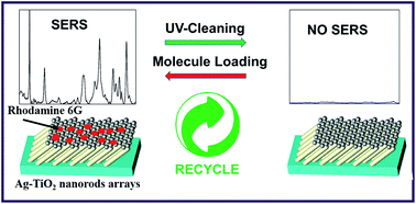
We report a facile method to fabricate novel Ag nanoparticle decorated TiO2 nanorod array substrates using a glancing angle deposition (GLAD) technique for photocatalysis and surface enhanced Raman scattering (SERS) applications. The silver nanoparticles on the TiO2 nanorods enhances the Raman signal of rhodamine 6G (Rh6G) dye with an enhancement factor ∼105. The photocatalytic degradation of Rh6G molecules present on Ag nanoparticle decorated TiO2 nanorods (Ag–TiO2) was also studied. The intensity of the Rh6G peak at 611 cm−1 decreases considerably (∼99%) after UV irradiation for 90 minutes. The change in SERS enhancement with time during ultra-violet (UV) light irradiation was used to track the photocatalytic degradation of the dye present on the Ag–TiO2 nanorods. The Ag–TiO2 SERS substrates can be recovered after 150 min in the presence of UV light illumination. The as-prepared Ag–TiO2 nanorods could be self-regenerated, fully recovered, and recycled after their use in the SERS analysis because of the self-cleaning property of TiO2 under simple UV light irradiation. This excellent SERS enhancement may be attributed to the formation of high density hotspots on top of the TiO2 nanorods which is supported by finite difference time domain (FDTD) simulations.


1. Introduction

Recently, photocatalysis has evolved as a topic of great interest, since the discovery of photocatalytic water splitting by Fujishima and Honda in 1972.1,2 It tackles numerous environmental and energy related problems by degradation of dye pollutants, hydrogen generation through water splitting and photoreduction of CO2 into valuable products.3–5 TiO2 is renowned for its photocatalytic properties in numerous nanostructural forms like nanoparticles, nanorods and nanotubes.6 The photocatalytic dye degradation properties of TiO2 nanostructures have been studied by various research groups and were found to be strongly dependent on the shape, size and crystal phase of the TiO2 nanostructures.7–9 Recent studies on noble metal–TiO2 nanocomposites have also shown their great potential to be used as photocatalysts and additionally as surface enhance Raman scattering (SERS) substrates.10–13 SERS is an enormous (∼1010) enhancement of the Raman signal intensity for molecules of interest in close proximity to plasmonic nanostructures.14 Noble metal nanostructures are renowned for their high SERS activity.15,16 The SERS technique is an ultrasensitive tool to provide molecular level information of surface absorbed chemical and biological species.17 The enhancement in the Raman signal of surface absorbed molecules predominantly depends upon the optical properties and morphology of the metal nanostructures. Noble metals notably Ag and Au have shown exceptional SERS activity in their varied nanostructural forms such as nanoparticles, nanorods, rough metal surfaces and ordered nanostructures.18–21 Origin of SERS activity lies in the electromagnetic and chemical enhancement of metal nanostructures.22 Electromagnetic enhancement is governed by the localized surface plasmon resonance on the metal nanostructures.23,24 On the other hand, the chemical enhancement is a result of charge interaction between the metal nanostructures and the absorbed Raman active molecules.25

Most of the standard SERS substrates are for one-time use only, and considering the valuableness of the noble metals, these SERS substrates cannot be completely explored as a routine analytical technique. Therefore, research has been focused on developing reusable SERS-active substrates. The recyclable SERS substrates have been reported by many researchers. For example, Alessandri and co-workers have investigated a straightforward and low-cost way to fabricate Au-coated ZnO nanorods.26 Their as-prepared substrates show excellent SERS and recyclable performances. Zhang et al. reported the fabrication of a periodic Ag nanoparticles decorated ZnO nanoflower arrays as recyclable SERS substrates using magnetron sputtering and photolithography.27 However, these nanocomposites were prepared by complex methods that limit their use. It has also to be noted that compared to ZnO, TiO2 is considered to be one of the suitable material for photocatalysts owing to its nontoxicity, biological inertness and chemical stability.28,29

Fabrication of TiO2 and metal–TiO2 nanostructures with high degree of reproducibility is extremely challenging. There are various methods with bottom-up approach like sol–gel, hydrothermal, chemical vapor deposition (CVD) that are being employed to fabricate TiO2 nanostructures such as nanobelts, nanowires, and three dimension (3-D) hierarchical nanostructures.30–32 For SERS and photocatalysis applications fabrication of reproducible and ordered nanostructures is a matter of great importance. The nanostructures grown by these methods are generally random and lack reproducibility. A multifunctional Au-coated TiO2 nanotube as a reproducible and recyclable SERS substrate for organic pollutants detection had been earlier reported by Li et al.33 However, the multifunction properties (such as self-cleaning and photocatalytic properties) of those SERS substrates are not obvious, and most of them are complicated and expensive.

To achieve that reproducibility, methods such as nanoimprint lithography, e-beam lithography and nanosphere coating are suggested. However, either they are very expensive or technologically demanding. Glancing angle deposition (GLAD) technique has emerged as versatile, simple reproducible and low cost technique to fabricate metal as well as metal oxide nanostructures for SERS and photocatalysis applications.34–36 It is a physical vapor deposition with vapor flux incident towards the substrate at very large angle (θ = 85°) with reference to the surface normal. Fabrication of 3-D ordered columnar nanostructures using GLAD is an artifact of shadowing effect that arise due to the large vapor incident angle (θ). Nanostructures like nanohelix and nanosprings can also be fabricated using GLAD with an extra degree of freedom by rotating the substrates azimuthally.37,38

In this work, we report a highly sensitive, reproducible and reusable Ag nanoparticle decorated TiO2 SERS substrate fabricated by GLAD technique. The self-cleaning ability of the Ag–TiO2 nanorods substrates based on the ultra violet (UV) light-induced photocatalytic decomposition was studied. In presence of UV light, intensity of Raman signal reduced rapidly due to the decrease in the concentration of absorbed dye molecules. Our Ag–TiO2 nanorods SERS substrates exhibit an excellent SERS performance, well evidenced by the finite difference time domain (FDTD) simulations. These Ag–TiO2 nanorods SERS substrates recovered absolutely after UV light illumination for about 150 minutes. This study suggests that Ag–TiO2 nanorods arrays substrates with stability and self-cleaning property can serve as excellent substrates for SERS sensing.

2. Experimental details

TiO2 nanorods arrays on glass substrates were fabricated using electron beam evaporation in GLAD geometry. The glass substrates were mounted in such a way that the incident vapor flux made a very high angle (α = 85°) with the substrate normal in order, so that the shadowing effect can result in the formation of slanted nanorods. The deposition rate was maintained 4.4 Å s−1 with a base pressure of about 2 × 10⁻⁶ Torr throughout the deposition. It is commonly established that the photocatalytic ability of TiO2 depends greatly on its crystal structure. The anatase form is typically more active than rutile and amorphous TiO2. We have annealed TiO2 nanorods at 500 °C for 30 min in ambient condition to crystalize the amorphous TiO2 to anatase crystal phase, in order to enhance their photocatalytic performance.39 After the deposition of TiO2 nanorods, Ag nanoparticles were deposited on top of the TiO2 nanorods. Throughout the Ag deposition, the incident vapor flux direction was maintained parallel to the substrate normal (α = 0°) as shown in Fig. 1.
image file: c6ra06163j-f1.tif
Fig. 1 Schematics of the deposition chamber used for the (a) deposition of TiO2 nanorods (b) deposition of Ag on TiO2 nanorods. The distance between the substrate and vapor source was 25 cm.

Crystal structure was identified using the glancing angle X-ray diffraction technique (GAXRD) at 1° glancing angle (Phillips X'Pert, PRO-PW 3040 diffractometer). The Raman measurements were performed using the Horiba LabRAM HR Evolution with 100× magnification and 2 s of acquisition time. A 514 nm Ar+ laser was used as an excitation source for Raman measurements. The surface morphology and structural analysis were performed using scanning electron microscope (SEM, ZEISS EVO 50) with LaB6 detector in the secondary electron mode operating at an acceleration voltage of 20 kV and transmission electron microscope (TEM) (JEM-1400 Plus transmission electron microscope with a LaB6 filament, operated at 120 kV) was used to study the size and structural properties of Ag–TiO2 nanorods.

Photocatalytic degradation measurements of rhodamine 6G (Rh6G) dye were carried out by measuring the change in the intensity of Raman signal of dye molecules with time, in presence of a UV lamp of 11 W power. Philips TUV-11 W, emitting in the UV-C (200–280 nm) region at 254 nm was used as UV source. The distance between UV source and samples was 5 cm. The photocatalytic measurements were performed at ambient pressure and temperature. The Raman measurements were done after an equal time interval of UV illumination. The dye molecules on Ag–TiO2 nanorods samples were deposited by immersing the Ag–TiO2 nanorods samples in 10−5 M aqueous solution of dye for about 1 hour. After the immersion, samples were dried using a gentle blow of dry nitrogen gas. Raman measurements for a specific sample were done at three different places on the samples and at each position an average of three spectra was taken. To investigate the photocatalytic properties of Ag–TiO2 nanorods the degradation of Rh6G was studied by observing the change in the Raman intensity of the prominent peak 611 cm−1 with time. The samples were irradiated by UV light and the Raman spectra was recorded after an equal interval of time of 30 minutes. To test the reusability and self-cleaning ability of the Ag–TiO2 nanorods substrates based on the UV light-induced photocatalytic decomposition, the substrate loaded with Rh6G molecules was immersed in the deionized water and then irradiated with the UV lamp at room temperature for a period of about 150 minutes. After that, the substrate was rinsed with deionized water several times to remove residual ions and molecules, and eventually dried out in ambient atmosphere and SERS measurements were then carried out. The method was continual for six times to ensure that the sample can be used as a new, clean SERS substrate after each cleaning process.

3. Results and discussion

The cross sectional SEM micrograph of TiO2 nanorods grown by GLAD is shown in Fig. 2(a). The length and diameter of TiO2 nanorods are 662 ± 10 nm and 90 ± 8 nm, respectively. The tilt angle of nanorods is 52 ± 2° with respect to the surface normal. Fig. 2(b) shows the SEM micrograph of Ag nanoparticles on top of TiO2 nanorods. Ag nanoparticles on top of TiO2 nanorods are in the form of non-spherical particles, which may be attributed due to the restriction of the surface diffusion of Ag on the top of the rough TiO2 nanorods samples. Silver was also deposited on TiO2 conventional thin film with the same deposition parameters. Interestingly, it was found that the Ag particles were not formed. Instead, a comparatively larger size (>200 nm) and random shape Ag islands were formed (ESI). The size of silver islands on TiO2 nanorods was found to vary from 70 nm to 100 nm with a mean value of 87 ± 8 nm. SERS activity of the noble metal nanostructures strongly depend upon size, roughness and periodicity.40,41 TEM analysis of the Ag–TiO2 samples were done to see the partial diffusion of the Ag into the TiO2 nanorods gap. From the Fig. 2(c) it is clear that there are formation of some Ag nanoparticles on the TiO2 surface which are smaller than that on top of TiO2 nanorods. During the initial growth of Ag nanoparticles, the impinging Ag atoms will form random isolated nucleation centers on the surface and on top of TiO2 nanorods which will cast shadow for the arriving vapor flux. As the nucleation center on top of the TiO2 nanorods will receive more impinging atoms as compared to the smaller islands on the surface of TiO2 nanorods it will grow and the shadowing effect will result in the growth of larger size of Ag nanoparticles on top of TiO2 nanorods.
image file: c6ra06163j-f2.tif
Fig. 2 (a) Cross sectional SEM image of TiO2 nanorods (b) SEM image of Ag deposited on TiO2 nanorods (c) TEM image of Ag–TiO2 nanorods.

The GAXRD spectra of TiO2 nanorods and Ag–TiO2 nanorods are shown in Fig. 3. The XRD spectra of TiO2 nanorods confirmed the presence of anatase phase after assigning peaks using the JCPDS data (JCPDS card no. 21-1272). The XRD spectrum of Ag–TiO2 nanorods contains four additional peaks attributed to Ag (200), (220) and (311) planes (JCPDS cards 4-0783). The intensity of Ag peaks was found relatively smaller which is due to the small quantity of Ag material on top of the TiO2 nanorods. SERS activity of Ag–TiO2 nanorods samples was examined by recording the Raman spectra of Rh6G. Fig. 4 shows the baseline corrected Raman spectra of Rh6G on Ag–TiO2 samples. The intensities of the most prominent Raman peaks of Rh6G enhanced enormously on Ag–TiO2 samples compared to that of conventional Ag thin film deposited on the glass substrates. The enhancement factor (EF) for the Ag–TiO2 samples was estimated using the conventional Ag thin film as a reference by using the following relation,

 
image file: c6ra06163j-t1.tif(1)
here IAg–TiO2 is that the intensity of Raman peaks for Ag–TiO2 samples, ITF is the intensity of Raman peaks for the conventional Ag thin film on glass substrates and IBKG is the background intensity. The EF was calculated to be ∼105 for the 611 cm−1 peak. This enhancement may be attributed to the presence of high density Ag nanoparticles on top of TiO2 nanorods. There are other reports in literature showing that the presence of silver particles on TiO2 can enhance the Raman spectra by a considerable amount.11,13,42


image file: c6ra06163j-f3.tif
Fig. 3 XRD spectra of anatase TiO2 nanorods and Ag particle decorated TiO2 nanorods.

image file: c6ra06163j-f4.tif
Fig. 4 Raman spectra of rhodamine 6G on Ag–TiO2 samples.

As for the contribution from the Ag nanoparticles partially deposited along the nanorods, if the excitation beam of visible range incidents normal to the substrate plane then it may illuminate only the top surface or apex of the inclined nanorods arrays, leaving a large surface area of the nanorods in shadow as shown in Fig. 5. The area in optical shadow may contribute only by scattering or multiple reflections of incident or emitted light. Therefore, in that case there may be some contribution from the Ag nanoparticles form the TiO2 surface but only the illuminated top surface of nanorods can make a significant contribution to the SERS phenomenon.


image file: c6ra06163j-f5.tif
Fig. 5 Schematic showing the exposed surface area of the inclined nanorods arrays for a normal incidence of the excitation beam in the visible range.

Fig. 6 shows change in the intensity of Raman spectra with the irradiation time. The all spectra shown are background subtracted. The intensity of Rh6G peak at 611 cm−1 decreases considerably (∼99%) after UV irradiation for 90 minutes. The decrease in the intensity of Raman signal indicates the degradation of surface absorbed Rh6G molecules in presence of UV light.


image file: c6ra06163j-f6.tif
Fig. 6 Raman spectra of rhodamine 6G on Ag–TiO2 samples in presence of UV light. Each spectrum was taken after an equal time interval (30 minutes) of UV irradiation.

These results indicate that the SERS spectra also can reflect the pseudo-first-order kinetics of this degradation reaction. The general photocatalytic reaction of Rh6G is as follows:

 
image file: c6ra06163j-t2.tif(2)

Generally, the photodegradation reaction of Rh6G can be described by classical Langmuir–Hinshelwood mechanism:43,44

 
image file: c6ra06163j-t3.tif(3)

Therefore, the photocatalytic activity of the synthesized catalyst can be quantitatively studied by the evaluation of k, where k is apparent-reaction-rate constant, C0 is initial concentration of Rh6G, C is the concentration of Rh6G depending on degradation time.

Earlier studies showed that the peaks intensity increases linearly with the amount of analyte adsorbed on the substrates.45 Zhao et al. showed that the SERS signals are related to the dye concentration and provides an excellent alternative to monitor the reaction process in the catalytic system.43

Hence we used the corresponding linear relationship of versus reaction time acquired from 611 cm−1 band (ESI). The k value from the slope of the straight line is 0.043 min−1.

The decrease in the intensity of 611 cm−1 peak for Ag–TiO2 nanorods, Ag–TiO2 thin film and conventional Ag thin film with UV irradiation time is shown in Fig. 7. Throughout UV irradiation, the samples were kept at ambient atmosphere so that the atmospheric oxygen and water molecules can take part in the photocatalytic process. In the Ag–TiO2 nanorods samples the SERS signal is around 7 times that of Ag–TiO2 thin film samples. Also on Ag–TiO2 thin film samples, the Rh6G degraded about 90% in 150 min. By contrast, the degradation time of 99% Rh6G on Ag–TiO2 nanorods samples is only 90 min. This result illustrate that the rate of degradation of dye can be obviously increased when Ag nanoparticles coated TiO2 nanorods are used.


image file: c6ra06163j-f7.tif
Fig. 7 Change in the intensity of 611 cm−1 peak with UV irradiation time for Ag–TiO2 nanorods, Ag–TiO2 thin film and for conventional Ag thin film.

TiO2 has attracted significant attention owing to its robust chemical stability and outstanding photocatalytic activity. As a photocatalyst, TiO2 is a semiconductor with a band gap of 3.2 eV (anatase) and is only activated by UV at wavelengths less than 385 nm to produce electrons and holes in the conduction and valence bands, respectively.46 The presence of Ag on Ag–TiO2 nanorods interface serves as an electron traps for the oxidizing and reducing agent, and electron transfer occur at the interface.47 The silver helps in the separation of the photo-generated electron–hole pairs (e–h+), which is beneficial for photocatalytic reactions. The presence of potential barrier reduces the probability of electron–hole pair recombination at the interface.48

Explicitly, when TiO2 is illuminated by UV light, it undergoes charge separation and the valence-band electrons are excited into the conduction band. The electron transfer from the TiO2 conduction band to Ag nanoparticles at the interface is thermodynamically possible because the Fermi level of TiO2 is higher than that of Ag, resulting in the formation of a Schottky barrier at metal–semiconductor interface. Therefore, Ag is an acceptor of the e transferred from TiO2 layers, whereas the holes remain in TiO2, thus improving the charge separation by suppressing the recombination of e–h+ pairs. The residual electrons on the Ag surface are then scavenged by the molecular oxygen to provide reactive oxygen radicals, while holes at the valence band of TiO2 form hydroxyl radicals by oxidization of H2O molecules present on the substrate surface. Organic molecules present in the solution can react with these oxidizing agents and can decomposed into small inorganic compounds.46,49

Consequently, the strong interaction between Ag and TiO2 would optimize the separation of photo-excited charge carriers, leading to a remarkable enhancement of the photocatalytic activity of TiO2. The recyclable property of this hybrid Ag–TiO2 SERS substrate is demonstrated through a series of repeated detection and self-cleaning experiments. Fig. 8 shows the SERS spectra from 10−5 M Rh6G recorded before and after each cyclic UV-irradiation treatment. The SERS spectrum shows that the main Raman peaks intensities gradually diminishes with time and finally the Raman spectrum of the sample approaches to that of a fresh SERS substrate without dye. This is attributed to the above mentioned mechanism that the target molecules adsorbed on the substrate gradually decompose by the UV light illumination. These results indicate that the Ag–TiO2 substrates can be used as a SERS substrate with high reproducibility and stability.


image file: c6ra06163j-f8.tif
Fig. 8 The variation is Raman intensity of Ag–TiO2 SERS substrate after UV-illumination cycles.

Furthermore, to analyze the origin of SERS enhancement by estimating the electromagnetic field distribution on the nanostructure, we have performed 3-D finite difference time domain (FDTD) numerical simulation. The model of structure utilized in simulation is shown in the Fig. 9(a), where the TiO2 nanorods of length 662 nm and diameter 90 nm with the Ag particles of 90 nm diameter on top were created to realize the real structures. The nanorods were arranged as an array of 2-D rhombic Bravais lattice with separation of 150 nm in both x- and y-directions on planer glass substrate. The cell size for the FDTD calculation was set as 2 nm and the time step for the calculation was taken to be less than 10−17 s resulting from the Courant stability condition that ensures the stability for the plane wave excitation with 514 nm wavelength. The periodic condition was used along the directions parallel to the substrate and perfectly matched layer boundary condition was used in the direction perpendicular to the substrate. The permittivity of Ag material was taken in consistent with the Drude model.50–52 The relative permittivity of TiO2 was taken as 2.4. The top view of electric field distribution on surface of the Ag particles in effect of excitation by a 514 nm plane electromagnetic wave with normal incident is shown in Fig. 9(b). The electric field increases significantly on top of Ag nanoparticles and in-between them, this is because of the electric field coupling between the silver nanoparticles and localized surface plasmon resonance effect which results in enhancement of Raman intensity of Rh6G molecules absorbed on the surface.53 Hot spots formation between the arrays of Ag particles has been well reported in the literature.12,54,55 The side view of the simulation results is shown in Fig. 9(c), where the electric field at the interface of Ag and TiO2 was found to be increased and this is because of the change in the dielectric properties of surroundings of (the presence of TiO2 which has high dielectric constant ∼2.43) the silver nanoparticles.56,57 Therefore, formation of hot spots between Ag particles and Ag–TiO2 interface may be responsible for the large enhancement in the Raman signal of Rh6G molecules.


image file: c6ra06163j-f9.tif
Fig. 9 (a) Model of structure having TiO2 nanorods decorated with the silver particles used in FDTD simulation (b) top view (XY) of simulation results a significant electric field enhancement on the surface of silver nanoparticles (c) side view (YZ) of simulation results showing an enhancement in the electric field distribution at the interface of Ag and TiO2.

4. Conclusions

In conclusion, the photocatalytic recyclable SERS substrates were fabricated by combining plasmonic metal (Ag) with semiconductor TiO2 using GLAD technique. The photocatalytic degradation of surface absorbed Rh6G molecules on silver decorated TiO2 nanorods was studied. The novel Ag–TiO2 nanorods samples were found to show high SERS enhancement factor of ∼105 with reference to the conventional silver thin film. The Ag–TiO2 SERS substrates recovered after 150 min in the presence of UV light illumination. These revived substrates have shown to be successfully reused for further SERS analyses with a correspondingly small decrease (on average 5% for each cycle) in the Raman intensity. This study suggests that Ag–TiO2 nanorods arrays substrates with stability and recyclable properties can serve as excellent substrates for SERS based sensing of hazardous chemicals and biological pathogens.

Acknowledgements

The author (DKL) is thankful to University Grant Commission (UGC) for providing the research fellowship. We are thankful to Dr Dhruv P. Singh and Prof. J. K. Kim of Pohang University of Science and Technology, S. Korea for providing TiO2 samples. We also acknowledge the Nanoscale Research facility (NRF), IIT Delhi for providing characterization facilities.

References

  1. A. Fujishima and K. Honda, Nature, 1972, 238, 37–38 CrossRef CAS PubMed.
  2. K. Hashimoto, H. Irie and A. Fujishima, Jpn. J. Appl. Phys., 2005, 44, 8269 CrossRef CAS.
  3. F. Han, V. S. R. Kambala, M. Srinivasan, D. Rajarathnam, R. Naidu, V. Subba, R. Kambala and M. Srinivasan, Appl. Catal., A, 2009, 359, 25–40 CrossRef CAS.
  4. M. Ni, M. K. H. Leung, D. Y. C. Leung and K. Sumathy, Renewable Sustainable Energy Rev., 2007, 11, 401–425 CrossRef CAS.
  5. S. N. Habisreutinger, L. Schmidt-Mende and J. K. Stolarczyk, Angew. Chem., Int. Ed., 2013, 52, 7372–7408 CrossRef CAS PubMed.
  6. X. Chen and S. S. Mao, Chem. Rev., 2007, 107, 2891–2959 CrossRef CAS PubMed.
  7. D. Tang, K. Cheng, W. Weng, C. Song, P. Du, G. Shen and G. Han, Thin Solid Films, 2011, 519, 7644–7649 CrossRef CAS.
  8. Z. Zhang, Y. Yuan, G. Shi, Y. Fang, L. Liang, H. Ding and L. Jin, Environ. Sci. Technol., 2007, 41, 6259–6263 CrossRef CAS PubMed.
  9. J. M. Macak, M. Zlamal, J. Krysa and P. Schmuki, Small, 2007, 3, 300–304 CrossRef CAS PubMed.
  10. A. Lamberti, A. Virga, A. Chiado, A. Chiodoni, K. Bejtka, P. Rivolo and F. Giorgis, J. Mater. Chem. C, 2015, 3, 6868–6875 RSC.
  11. E.-Z. Tan, P.-G. Yin, T.-T. You, H. Wang and L. Guo, ACS Appl. Mater. Interfaces, 2012, 4, 3432–3437 CAS.
  12. D. Han, H. Huang, D. Du, X. Lang, K. Long, Q. Hao and T. Qiu, Mater. Chem. Phys., 2015, 153, 88–92 CrossRef CAS.
  13. Z. Dai, G. Wang, X. Xiao, W. Wu, W. Li, J. Ying, J. Zheng, F. Mei, L. Fu, J. Wang and C. Jiang, J. Phys. Chem. C, 2014, 118, 22711–22718 CAS.
  14. M. Moskovits, Rev. Mod. Phys., 1985, 57, 783 CrossRef CAS.
  15. M. B. Müller, C. Kuttner, T. a. F. König, V. V. Tsukruk, S. Förster, M. Karg and A. Fery, ACS Nano, 2014, 8(9), 9410–9421 CrossRef PubMed.
  16. P. K. Jain, X. Huang, I. H. El-Sayed and M. A. El-Sayed, Acc. Chem. Res., 2008, 41, 1578–1586 CrossRef CAS PubMed.
  17. S. Nie and S. R. Emory, Science, 1997, 275, 1102 CrossRef CAS PubMed.
  18. S. Shanmukh, L. Jones, J. Driskell, Y. Zhao, R. Dluhy and R. a. Tripp, Nano Lett., 2006, 6, 2630–2636 CrossRef CAS PubMed.
  19. H.-H. Wang, C.-Y. Liu, S.-B. Wu, N.-W. Liu, C.-Y. Peng, T.-H. Chan, C.-F. Hsu, J.-K. Wang and Y.-L. Wang, Adv. Mater., 2006, 18, 491–495 CrossRef CAS.
  20. X. Li, H. Hu, D. Li, Z. Shen, Q. Xiong, S. Li and H. J. Fan, ACS Appl. Mater. Interfaces, 2012, 4, 2180–2185 CAS.
  21. S. Kumar, D. K. Lodhi, P. Goel, Neeti, P. Mishra and J. P. Singh, Chem. Commun., 2015, 51, 12411–12414 RSC.
  22. A. Campion, P. Kambhampati and C. Harris, Chem. Soc. Rev., 1998, 27, 241–250 RSC.
  23. S. J. Lee, Z. Guan, H. Xu and M. Moskovits, J. Phys. Chem. C, 2007, 111, 17985–17988 CAS.
  24. S. J. Lee, A. R. Morrill and M. Moskovits, J. Am. Chem. Soc., 2006, 128, 2200–2201 CrossRef CAS PubMed.
  25. M. M. Maitani, D. A. A. Ohlberg, Z. Li, D. L. Allara, D. R. Stewart and R. S. Williams, J. Am. Chem. Soc., 2009, 131, 6310–6311 CrossRef CAS PubMed.
  26. G. Sinha, L. E. Depero and I. Alessandri, ACS Appl. Mater. Interfaces, 2011, 3, 2557–2563 CAS.
  27. Q. Tao, S. Li, C. Ma, K. Liu and Q. Zhang, Dalton Trans., 2015, 3447–3453 RSC.
  28. J. F. Li, Y. F. Huang, Y. Ding, Z. L. Yang, S. B. Li, X. S. Zhou, F. R. Fan, W. Zhang, Z. Y. Zhou, D. Y. Wu, B. Ren, Z. L. Wang, Z. Q. Tian, W. Yin, B. Ren, Z. L. Wang and Z. Q. Tian, Nature, 2010, 464, 392–395 CrossRef CAS PubMed.
  29. A. K. Chakraborty, Z. Qi, S. Y. Chai, C. Lee, S. Y. Park, D. J. Jang and W. I. Lee, Appl. Catal., B, 2010, 93, 368–375 CrossRef CAS.
  30. J. Du, J. Zhang, Z. Liu, B. Han, T. Jiang and Y. Huang, Langmuir, 2006, 22, 1307–1312 CrossRef CAS PubMed.
  31. Q. Xiang, J. Yu, B. Cheng and H. C. Ong, Chem.–Asian J., 2010, 5, 1466–1474 CAS.
  32. J. Yu, J. Xiong, B. Cheng and S. Liu, Appl. Catal., B, 2005, 60, 211–221 CrossRef CAS.
  33. X. Li, G. Chen, L. Yang, Z. Jin and J. Liu, Adv. Funct. Mater., 2010, 20, 2815–2824 CrossRef CAS.
  34. K. Robbie, J. Vac. Sci. Technol., A, 1997, 15, 1460 CAS.
  35. S. Kumar, P. Goel, D. P. Singh and J. P. Singh, Appl. Phys. Lett., 2014, 104, 023107 CrossRef.
  36. Y. Zhao, D. Ye, G.-C. Wang and T.-M. Lu, Opt. Sci. Technol. SPIE's 48th Annu. Meet., 2003, vol. 5219, pp. 59–73 Search PubMed.
  37. H. Kwon, S. H. Lee and J. K. Kim, Nanoscale Res. Lett., 2015, 10, 1–12 CrossRef CAS PubMed.
  38. J. P. Singh, T. Karabacak, D.-X. Ye, D.-L. Liu, C. Picu, T.-M. Lu and G.-C. Wang, J. Vac. Sci. Technol., B: Microelectron. Nanometer Struct.–Process., Meas., Phenom., 2005, 23, 2114 CrossRef CAS.
  39. J. Xu, X. Xiao, F. Ren, W. Wu, Z. Dai, G. Cai, S. Zhang, J. Zhou, F. Mei and C. Jiang, Nanoscale Res. Lett., 2012, 7, 1–6 CrossRef PubMed.
  40. D. P. Singh, S. Kumar and J. P. Singh, RSC Adv., 2015, 5, 31341–31346 RSC.
  41. Z. Tian, B. Ren and D. Wu, J. Phys. Chem. B, 2002, 106, 9463–9483 CrossRef CAS.
  42. M. Fan and A. G. Brolo, Phys. Chem. Chem. Phys., 2009, 11, 7381–7389 RSC.
  43. X. Zhao, B. Zhang, K. Ai, G. Zhang, L. Cao, X. Liu, H. Sun, H. Wang and L. Lu, J. Mater. Chem., 2009, 19, 5547–5553 RSC.
  44. H. E. Zhong, Y. Shaogui, J. U. Yongming and S. U. N. Cheng, J. Environ. Sci., 2009, 21, 268–272 CrossRef.
  45. X. X. Han, H. Y. Jia, Y. F. Wang, Z. C. Lu, C. X. Wang, W. Q. Xu, B. Zhao and Y. Ozaki, Anal. Chem., 2008, 80, 2799–2804 CrossRef CAS PubMed.
  46. M. Miyauchi, A. Nakajima, K. Hashimoto and T. Watanabe, Adv. Mater., 1923, 2000 Search PubMed.
  47. C. Kormann, D. W. Bahnemann and M. R. Hoffmann, J. Phys. Chem., 1988, 92, 5196–5201 CrossRef CAS.
  48. T. Hirakawa, P. V Kamat, T. Hirakawa, P. V. Kamat, T. Hirakawa and P. V. Kamat, J. Am. Chem. Soc., 2005, 127, 3928–3934 CrossRef CAS PubMed.
  49. Y. Li, T. Sasaki, Y. Shimizu and N. Koshizaki, J. Am. Chem. Soc., 2008, 130, 14755–14762 CrossRef CAS PubMed.
  50. E. Hao and G. C. Schatz, J. Chem. Phys., 2004, 120, 357–366 CrossRef CAS PubMed.
  51. R. Thomas, J. Kumar, R. S. Swathi and K. G. Thomas, Curr. Sci., 2012, 102, 85–96 CAS.
  52. J. P. Singh, T. E. Lanier, H. Zhu, W. M. Dennis, R. A. Tripp and Y. Zhao, J. Phys. Chem. C, 2012, 116, 20550–20557 CAS.
  53. J. A. Dieringer, K. L. Wustholz, D. J. Masiello, J. P. Camden, S. L. Kleinman, G. C. Schatz and R. P. Van Duyne, J. Am. Chem. Soc., 2009, 131, 849–854 CrossRef CAS PubMed.
  54. J. Kumar and K. G. Thomas, J. Phys. Chem. Lett., 2011, 2, 610–615 CrossRef CAS.
  55. S. B. Chaney, S. Shanmukh, R. a. Dluhy and Y.-P. Zhao, Appl. Phys. Lett., 2005, 87, 031908 CrossRef.
  56. K. L. Kelly, E. Coronado, L. L. Zhao and G. C. Schatz, J. Phys. Chem. B, 2003, 107(3), 668–677 CrossRef CAS.
  57. T. Wang, Z. Zhang, F. Liao, Q. Cai, Y. Li, S.-T. Lee and M. Shao, Sci. Rep., 2014, 4, 4052 Search PubMed.

Footnotes

Electronic supplementary information (ESI) available. See DOI: 10.1039/c6ra06163j
Both the authors SK and DKL contributed equally.

This journal is © The Royal Society of Chemistry 2016
Click here to see how this site uses Cookies. View our privacy policy here.