A review of harvesting clean fuels from enzymatic CO2 reduction

Sabiha Sultana , Prakash Chandra Sahoo *, Satyabadi Martha and Kulamani Parida *
Centre for Nano Science and Nano Technology, ITER, Siksha ‘O’ Anusandhan University, Bhubaneswar – 751030, Odisha, India. E-mail: kulamaniparida@soauniversity.ac.in; prakash200920@gmail.com; Fax: +91-674-2351217; Tel: +91-674-2350181

Received 1st March 2016 , Accepted 16th April 2016

First published on 18th April 2016


Abstract

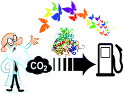
Rapid climate change and increase in the demand for hydrocarbon fuels have made the research community to recheck the carbon dioxide (CO2) concentration and its utilization in a green and efficient way. One of the best ways to utilize CO2 so far considered is its conversion back into fuels using various strategies such as thermal, photochemical, electrochemical and enzymatic. In this critical review the concepts and mechanism of CO2 reducing biocatalysts have been summarized. Specifically, more emphasis was given to enzymes related to the selective conversion of CO2 to fuels (popularly known as artificial photosynthesis). Emphasis has been given to single enzyme and multi-enzymatic systems for CO2 conversion to carbon monoxide, methanol, and formic acid/formate. Semiconducting nano-material integrated enzymatic systems and their mechanism are reviewed and described in detail. Finally, the ultimate challenges underlying the design of next generation enzymatic catalysts are explored.


image file: c6ra05472b-p1.tif

Sabiha Sultana

Ms Sabiha Sultana received her bachelor's degree from Utkal University, Bhubaneswar in 2012 and an MSc in Chemistry from Ravenshaw University, Cuttack in 2014. Then, she joined the Centre for Nano Science and Nano Technology, ITER, SOA University as a PhD student under the supervision of Prof. K. M. Parida in 2015. Her research area focuses on the development of nanostructured metal oxide and its application towards enzymatic carbon dioxide utilisation.

image file: c6ra05472b-p2.tif

Prakash Chandra Sahoo

Dr Prakash C. Sahoo completed his MSc in 2008, and his MPhil in 2010 in chemistry from Utkal University, India. He then moved to South Korea for his doctoral degree. In 2013 he completed his PhD study in Resources Recycling from the University of Science and Technology (UST) at the Korea Institute of Geosciences and Mineral Resources (KIGAM) campus, Daejeon, South Korea. During his PhD he studied biomimetic carbon dioxide sequestration. He was the winner of second overseas exchange program to France at UST-2013. In 2013 he started his job as a post-doc in Prof. Jay H Lee's group at the Korea Advanced Institute of Science and technology (KAIST), in the Chemical and Biomolecular Engineering Department, Daejeon, South Korea. He has published 12 research articles in international journals, has three international patents and presented his works in several national and international symposia and conferences. Currently (from January 2015) he is working as an assistant professor in the Center for Nano Science and Nano Technology, Department of Chemistry at Siksha ‘O’ Anusandhan University (SOA).

image file: c6ra05472b-p3.tif

Satyabadi Martha

Dr Satyabadi Martha completed his MSc in 2008 at the Utkal University, Bhubaneswar. Then, he completed his PhD degree from North Orissa University under the guidance of Prof. Kulamani Parida. His research work focused on the development of visible light responsive photocatalysts for hydrogen production, carbon dioxide reduction and pollution abatement. He also spent one year at the School of Energy and Chemical Engineering, UNIST, South Korea as a postdoc researcher with Prof. Jae Sung Lee. He has published 26 research articles in international journals and has three national patents and has presented his works at several national and international symposia and conferences. Now, he is working as assistant professor at the Centre for Nanoscience and Nanotechnology, ITER, at the SOA University. Currently, his research work focuses on powder and film-based semiconductor material for solar fuel production.

image file: c6ra05472b-p4.tif

Kulamani Parida

Prof. Kulamani Parida is currently working as professor in Chemistry and Director at the Centre for Nano Science and Nano Technology, ITER, at the SOA University, Bhubaneswar. Before coming to ITER, he worked as Chief Scientist and Head of the Colloids and Materials Chemistry Department at the CSIR Institute of Minerals and Materials Technology, Bhubaneswar, Odisha, India and was also Professor at the Academy of Scientific and Innovative Research (AcSIR), New Delhi, India. He is the author of more than 290 papers in international journals and has 18 national and international patents and has also written three book chapters. His research interest focuses on the design and development of materials comprising a wide cross section such as metal oxides, metal phosphates, metal sulfates, cationic and anionic clays, perovskites, zeolites, graphene, carbon nitride and nano metal/metal oxide/complex promoted mesoporous materials, and naturally occurring materials such as manganese nodules, manganese nodule leaching residue, manganese oxides of natural origin for energy and environmental applications.


1. Introduction

Global climate change and scarcity of energy resources will cause large problems for humanity, and it’s unclear as to how these problems are going to be resolved. The rapid increase in population and the demand for energy resources make the situation more complicated. As the major portion (80%) of the energy requirement of the world's population is met from fossil fuels (natural gases, coal, petroleum),1 this results in increased greenhouse gases (GHG) which have led to climate change, acid rain, ozone layer depletion, global warming, rise in sea level and many more environmental problems.2 The various studies by the intergovernmental panel on climate change (IPCC)3,4 have concluded that, among various anthropogenic GHG emissions, carbon dioxide (CO2) emissions produced from burning the fossil fuels are considered to be the main culprit behind climate change and global warming.5 Methane, nitrous oxide, fluorinated gases (F-gases; Fig. 1a) and so on are considered to be non-CO2 GHGs, and their impact upon climate cannot be neglected. But, as shown in a recent study, it was observed that from all the other non-CO2 GHGs, increasing amount of CO2 dominated the change in direct radiative forcing from 2004–2009. In order to stabilise the direct radiative forcing, it is estimated that an 80% reduction in the total emission of CO2 is needed. If this 80% reduction in anthropogenic CO2 can be achieved, then the environment could eventually be stabilised from the effects of radiative forcing from all other non-CO2 GHGs.6 It was shown that from the pre-industrial time (prior to 1750) the amount of anthropogenic CO2 has increased up to 30%, from a level of 280 ppm to 400 ppm today. The present CO2 levels in the atmosphere are higher than at any time during the last 650[thin space (1/6-em)]000 years for which the reliable data was extracted from the ice cores.7,8 In fact, Joseph Fourier first noted the impact and cause of the CO2 related greenhouse effect in 1824 and he was further supported by Svante Arrhenius in 1896.9 With the support of the current literature survey, it reveals that an increase in anthropogenic CO2 concentration is regarded as a forcing mechanism on the global climate because of its infrared absorbing capacity and it has a large and predictable effect on the temperature which makes it a primary driver of global warming.9,10 Based on the recent IPCC report calculation it was shown that between 1750 and 2011, around 2040 ± 310 Gt of cumulative anthropogenic CO2 was emitted to the atmosphere, from where about 40% of these emissions have remained in the atmosphere (880 ± 35 Gt CO2) and the remainder was removed from the atmosphere and remained in the ocean and on land (in soils and in plants as glucose). The ocean has absorbed about 30% of these emitted anthropogenic CO2, causing ocean acidification. In other words atmospheric CO2 was absorbed by sinks, and stored in natural carbon cycle reservoirs. By mimicking nature's key engineering principles the remaining CO2 can be utilised to create useful chemicals.
image file: c6ra05472b-f1.tif
Fig. 1 (a) A comparative analysis of all GHG emission in Gt of CO2 equivalent per year. F-Gases are the fluorinated gases (hydrofluorocarbons (HFCs), perfluorinated compounds (PFCs), sulfur hexafluoride (SF6) and nitrogen fluoride (NF3)) and are categorised under GHG after the Kyoto protocol and (b) contribution of different sources towards the world's energy economy.

Carbon dioxide, in general, is a very stable and non-flammable compound. At normal pressure and temperature, it is odourless, colourless, and heavier than air, with a slightly pungent odour. It has wide applications and it is used for many purposes in many industries, such as in cooling (solid ice), agro-production for conservation, and for medical applications. It is known to be produced during fermentation, combustion and putrefaction. Below its immediately lethal concentration, CO2 has long been considered as a neutral compound in the human body. The maximum acceptable concentration of CO2 lies between 0.5 and 3% but long term exposure of a minimum concentration of CO2 may be dangerous for health.10 So a rise in CO2 concentration in the atmosphere is a warning for the future and this was debated extensively at the Paris summit in 2015 (COP-21). The remaining anthropogenic CO2 should be minimized in order to avoid any disturbances in natural cycles, the environment and also to human and animal life.

In order to alleviate anthropogenic CO2 emission, different strategies have been proposed by various scientific communities. Among them the first way proposed is to reduce the direct emission of CO2, which is quite impossible because of insufficient alternative energy sources. However, because of the rising population, plentiful energy sources are required and their demand is only fulfilled by using fossil fuels11 (Fig. 1b) which ultimately leads to a huge anthropogenic CO2.

Carbon dioxide capture and storage is a second useful technique for CO2 minimization. At present, the readily available technology to tackle CO2 associated global warming problem is the carbon capture and storage (CCS) process. In this technology CO2 is captured and stored in risk free, secure places such as depleted coal seams, under the sea at deep levels and so on.12–14 It is limited because of the high energy requirement for gas transportation and compression and there is also a risk of leakage to environment. The continuous catalyst regeneration (CCR) process (i.e., capturing the CO2 and reusing it) has been considered to be a valuable and economical choice in comparison to the traditional CCS process. Besides economic benefits, the socio-political benefits also come in terms of a positive image for companies adopting policies of reusing the CO2 generated from fossil fuels.9

A third alternative is to convert the anthropogenic CO2 in to useful chemicals by reducing it. Various methods have been proposed for this: electrochemical conversion,15–18 photochemical conversion,19–22 thermochemical23–25 and so on. However, these technologies have drawbacks such as a high temperature and electricity requirements, drastic conditions, low selectivity of products (formation of more than one product unselectively) and so on.

Fossil fuels are the most important source of energy and human dependence on them increases day by day because of their high energy density, high stability and because they are readily available and easy to store and transport.26 But these sources are non-renewable and their amount is depleted continuously. So nowadays the search for inexpensive and plentiful energy supplies appears to be at odds with climate change mitigation commitments.27 So, different fuels have been proposed as alternatives to fossil fuels. Hydrogen (H2) has emerged as an appealing energy resource for the future generation energy systems. It has the capability to minimize pollution as well as rechecking the greenhouse gas emissions, that since the beginning of the industrial revolution have been plaguing mankind.28 But there are some disadvantages for H2 being used as a fuel. Its production is a highly labour intensive, energy consuming process. It is neither acceptable as a means to save energy nor for its subsequent use as a fuel. The handling of potentially explosive and volatile (boiling point: −253 °C) H2 gas which has negative Joule–Thomson coefficient, requires special conditions such as high pressure, use of special materials to minimize leakage and diffusion, and extensive safety precautions. Even so, its potential use as a fuel is limited because any leaks could be potential explosion hazards,29 whereas hydrocarbon fuels do not suffer from these severe drawbacks. For a long-term solution to mankind's need of fuels as well as for efficient storage of energy generated, a non-fossil fuel source is needed. The utilization and recycling of the anthropogenic atmospheric carbon CO2 itself through its reduction to use of hydrocarbon fuel such as methanol (CH3OH), formic acid (HCOOH), carbon monoxide, formaldehyde (HCOH) offers a new feasible alternative.29

Very recently CO2 utilisation by a process of reduction has emerged as an exciting field of research. The use of CO2 by green plants for photosynthesis is an excellent method for its utilisation, whereas the natural processes are very slow and complicated. A natural enzymatic system has been established as an efficient green method which selectively generates products with high yield at milder conditions. Enzymatic reduction offers a green, promising approach for CO2 reduction. In general, an enzymatic reduction system is composed of several enzymes individually or combined with a number of other enzymes, in order to perform their action on a substrate. In a CO2 reduction system enzymes are sometimes used as an electrocatalyst or they are integrated with a photocatalyst which harvests sunlight and convert it into chemical energy in the form of hydrocarbon fuel. This photocatalyst integrated system offers an artificial photosynthetic route which will become a key system for future generation of solar fuels. In this critical review the recent trends of the enzymatic CO2 reducing system have been summarized and are discussed with a detailed and mechanistic approach.

2. Basic principles leading to CO2 reduction

Carbon dioxide in its ground state is a linear, non-polar molecule containing two double bonds with a bond length of 1.17 Å between the carbon and oxygen. Carbon exhibits its highest oxidation state (+4) in this molecule and it is the ultimate product of most of the oxidation processes in biology as well as in chemistry. So it is a thermodynamically as well as kinetically stable molecule.30 However, its low energy level has discouraged its use as a carbon source. Consequently, a large energy input is required for its transformation. However, because of its electron deficiency, it has a high affinity towards electrophiles and nucleophiles.31

Reduction of CO2 is a highly unfavourable endergonic process. The majority of CO2 reduction processes (eqn (2)–(6)) is highlighted between −0.24 V and −0.6 V, but the major problem is the single electron reduction (eqn (1)) of CO2 at −1.90 V which makes the single electron reduction reaction extremely unfavourable. In addition, there is a huge kinetic overvoltage required for the one electron reduction because of the structural differences between bent CO2˙ and linear CO2 which can be clearly seen by Walsh's diagram (Fig. 2a).30

Reactions, E° (V vs. NHE)
 
CO2 + 2e → CO2˙, −1.90 (1)
 
CO2 + 2H+ + 2e → HCOOH, −0.61 (2)
 
CO2 + 2H+ + 2e → CO + H2O, −0.53 (3)
 
CO2 + 4H+ + 4e → HCHO + H2O, −0.48 (4)
 
CO2 + 6H+ + 6e → CH3OH + H2O, −0.38 (5)
 
CO2 + 8H+ + 8e → CH4 + 2H2O, −0.24 (6)


image file: c6ra05472b-f2.tif
Fig. 2 (a) Walsh diagram for the total energies upon CO2 bending and (b) molecular orbitals of CO2 at certain OCO angles (reprinted with permission from ref. 30, license no. 3845730801023).

A large amount of energy input is required to convert CO2 to other reduced species. But the energy involved in the formation of CO2˙ is much greater than that for the other reduced species. It is may be because of to the sizable reorganization energy attendant with the conversion of the linear CO2 molecule to the bent radical anion CO2˙. So its reduction is typically identified by a considerable decrease in the OCO angle besides the expected C–O bond lengthening. Originally for CO2 lowest unoccupied 2πμ molecular orbital is doubly degenerate and is composed of two antibonding π-orbitals which are orthogonal in nature. The injection of a single electron to the lowest unoccupied molecular orbital (LUMO) is energetically difficult, so a large over voltage is required. However, after the injection of electron, CO2 bending (134°) results in lowering the energy of its LUMO (2πμ), which is originally placed high enough in linear form (Walsh's diagram) as shown in Fig. 2b. Thus the enhancement in the electron accepting tendency of CO2 occurs which is favourable for other reduction. Such geometric distortion in fact entails a significant energetic expense as evidenced by the sufficiently negative potential for the one electron reduction.30,32–34

The reduction reactions of CO2 which are listed in eqn (2)–(6) all take place at much lower potentials than the first single electron reduction reactions. This may be because each of these reduction reactions involves the transfer of multiple reducing equivalents, and as a result, the formation of the high energy intermediate, CO2˙ will be circumvented. Additionally, each of these reduction reactions are associated with the transfer of an equal number of protons. More stable intermediates are formed for these multi-electron proton coupled electron transfer reactions (PCET) than the single electron reduction of CO2. Four of the last PCET reactions (eqn (3)–(6)) result in the formation of reduced carbon containing species in addition to the formation of at least one equivalent of water (H2O). Because water is a very stable molecule, its formation helps to offset the energy needed to drive these CO2 reduction processes.34 This explains the kinetics of CO2 reduction reactions, but the thermodynamics behind these reactions are quite different.

Because of the high stability (ΔG°), a substantial energy input, optimized reaction conditions, and catalysts with high stability and activity are required to convert CO2 into value added chemicals.8 According to the Gibbs–Helmholtz relationship for chemical reactions, differences between the Gibbs' free energy of reactants and products under certain conditions mainly drives the chemical reactions. The terms associated with Gibbs free energy (TΔS° and ΔH°) are not favourable for converting CO2 into other valuable products.9 A high energy input is required for dissociating the bonds in CO2 as the carbon–oxygen bonds are very strong. Similarly the entropy term (TΔS°) is also not a thermodynamic driving force for any of the reactions involving CO2. In fact the enthalpy term (ΔH°) can be conveniently considered for assessing the thermodynamic feasibility and stability of any CO2 conversion. However, it was suggested that a positive change in free energy should not be considered as sufficient reason for not pursuing potentially useful reactions of CO2 reduction which would give value added products. Even though ΔG° gives discouraging values for the formation of products at equilibrium through the relationship (ΔG° = −RT[thin space (1/6-em)]ln[thin space (1/6-em)]k), kinetics do favour certain reactions. Thus, in order to convert CO2 into value added chemicals, a good catalytic system is required. The thermodynamics of CO2 and its complications can easily be understood by studying the Frost diagram (Fig. 3). According to the Frost diagram, on the vertical axis, elements of the most stable oxidation state are placed. Oxidants and high energy fuels are placed higher up at the right and left sides of the diagram, respectively. The slope of the line joining two couples gives the reduction potential of their inter-conversion. The intermediates present above these gradients are quite unstable with respect to disproportion. Those with steeper slopes require more energy input for their interconversion. Also, the Frost diagram shows the concept of overpotential. It is the angular difference between the line joining of a couple and the potential, i.e., that which is actually required to drive the reaction. This is generally wasted energy and it can practically be influenced by the catalyst which will stabilise the inbetween intermediate. From Fig. 3 it is seen that CO2 reduction is much more difficult than water splitting. It has been seen that a single electron reduction of CO2 is an uphill process, as the large, albeit minimal, overpotential is required for continuing the reaction. Whereas, reduction to formate and CO is much more favourable as it has gone through the PCET reactions. However, reduction of CO2 to HCOH is the most energetically costly step, but the later reduction steps serve mainly to store equivalents of H2 generated upon conversion from CO2 to CH3OH and methane. In this review, how the enzymes (which are substrate specific in nature) facilitate these PCET reactions by avoiding the unwanted intermediates efficiently will be discussed.35–37


image file: c6ra05472b-f3.tif
Fig. 3 Frost diagram showing redox reactions of CO2, H2O, H2 and their intermediate products (reprinted with permission from ref. 37).

3. Structural aspects and active sites of CO2 reducing enzymes

In chemical transformation, catalysis is a key phenomenon. Among the various catalysts, enzymes are amazing molecular devices that determine the pattern of chemical transformations and can also transform one form of energy to another. All the metabolic pathways are catalyzed by enzymes. In other words no life form would ever exist without enzymes. These are multi-faceted accelerators that can accelerate enormous reactions under a wide range of conditions.38 Each day, the number of commercial applications for enzymes are increasing. This represents a remarkable diversity of substrate and reaction specificities. Using intermolecular forces, enzymes bring substrates collectively into an optimal orientation leading to the making and breaking of chemical bonds. They catalyze the reactions by stabilizing transition states (highest energy species in reaction pathways). By selectively stabilizing a transition state, an enzyme determines which one of the several declining processes is feasible.39,40 Enzymes allow systematic processing as they can make use of low impurity substrates and tolerate many impurities.41 In biocatalytic systems, isolated and purified enzymes are used as a catalyst but in some cases whole microbial cells are also used as a catalytic unit.42 This avoids the cascade process by conversion of substrate directly into product through its living metabolic pathway. This results in the elimination of the elementary enzyme purification process and supplementary addition of cofactor. But the effectiveness of whole microbial cell catalyzed bio-reduction process is inhibited by any noticeable toxicity of either substrate or product. Compared to the microorganism, enzymes have the advantage of not dispensing resources for biomass production and do not require careful conditions to keep them alive. So enzymes are excellent biocatalysts.43–45 As already discussed, conversion of CO2 into fuels is an energetic and expensive process, and requires a huge amount of energy. By using the enzyme as a catalyst, the reduction process becomes feasible. These biocatalysts easily stabilize the high energetic intermediate through proton coupled electron transfer reactions and generate products in high yield. In the following sections different CO2 catalysing enzymes are discussed.

3.1. Oxidoreductase–dehydrogenase

A large number of enzymes were discovered to belong to the oxidoreductase family. The main function of the oxidoreductase class of enzymes is to transfer the electron from an oxidant to a reductant. In some cases, some enzymes of this class catalyze those reactions involving direct molecular oxygen involvement. In this paper, the sub-classes of enzymes that oxidize the primary substrate by transferring the electrons/H2 to an acceptor, generally termed as dehydrogenase, will be concentrated on. These dehydrogenases are the basic class of enzymes which take part in CO2 reduction activity. Some of the dehydrogenases specifically provide appropriate catalytic sites for CO2 and its intermediates. Most of the CO2 and its intermediate (HCOOH and HCOH) reducing dehydrogenases possess a cofactor such as nicotinamide adenine dinucleotide-H2 (NADH), nicotinamide adenine dinucleotide phosphate-H2 (NADPH) and so on, which have binding sites which donate electrons or H2 to carry out the reaction. The detailed mechanism of the reductions is described in the next section. Structurally NAD+-dependent dehydrogenase is mainly divided into two domains, a catalytic binding domain and a co-enzyme/NAD+ binding domain.46 Each of the domains contains three polypeptide chains arranged in a super secondary structure. It also has a β sheet arranged in parallel with a left-handed twist next to a number of α-helices which are located in a fixed orientation. The NAD+ binding domain of the dehydrogenase family shows the Rossmann fold structure with a spatially conserved area.47 The Rossmann fold mainly represents the mononucleotide binding sub-domains. In the active conformation, this structure of NAD+ binding domain is responsible for binding and recognition of the cofactor NAD+/NADH. The NAD+ binding domain is nearly the same for all the enzymes of the dehydrogenase class. In contrast, the catalytic domain is different for different enzymes. It contains the amino acid residues which are in the proper orientation in the catalytic side responsible for effective catalysis.46–48 In the present review, CO2 reduction by different dehydrogenases such as carbon monoxide dehydrogenase (CODH), formate dehydrogenase (FDH), formaldehyde dehydrogenase (FaldDH) and alcohol dehydrogenase (ADH) are discussed in detail.

3.2. Carbon monoxide dehydrogenase (CODH)

This is a type of dehydrogenase enzyme which readily converts CO2 into carbon monoxide (CO) in the presence of a suitable electron donor as per the equation below. The various types of electron donor such as NADH, NADPH, MV2+, and so on can be used by the enzyme. According to the enzyme commission, it is categorised as EC 1.2.99.2.
CO2 + 2H+ + 2e ↔ CO + H2O, CODH, electron donor

Two types of CODHs have so far been identified in nature by the distinct structure of their active site. Some aerobes use enzymes containing a μ-sulfido bridged copper–sulfur–molybdenum (Cu–S–Mo) centre.48 However, some anaerobic micro-organisms contain nickel (Ni) and iron (Fe) as shown in Fig. 4, which catalyses the reversible redox reaction of CO/CO2 and the synthesis of acetyl-coenzyme A (acetyl-CoA).49 CODHs have a α2β2 quaternary structure with metal ions organized into four types of cluster: A, B, C, D. The C-cluster is only responsible for the CO/CO2 chemistry.50 The active site [NiFe] CODHs (C-cluster) contains a co-ordinatively unsaturated Ni centre bound to three sulfur ligands and a dangling Fe centre which is co-ordinated by cysteine (Cys), histidine (His), sulfido and an H2O/OH ligand. Both ions are bridged by an iron(II, III) sulfide (Fe3S4) cluster and are positioned in close proximity. At first, CO2 is bound to the Ni centre and stabilized by the Fe centre, only then does the reduction occur.48,50 In terms of the subunit components and metabolic role of the enzymes, Ni-CODHs have been divided into four classes. Among them class IV and class III enzymes are involved in the process of reduction where all the class IV enzymes contain a dimeric structure, each monomer consists of a C-cluster [Ni3Fe4S] and a dangling Fe or extra cuboidal pendant. The Ni-CODH family is extended to include the class III enzymes known as CODH/acetyl-COA synthetase (ACS) (EC 1.2.7.4) a bifunctional 310 kDa α2β2 tetramer in which an ACS is strongly associated with Ni–Fe–CODH.52 The CODH/ACS comprises four subunits: two CODH proteins and two ACS proteins. The β subunits of ACS/CODH are homo-dimeric in nature which is homologous to simple CODH enzymes found in carboxydotrophic bacteria. Each β subunit contains a novel active site C-cluster [Ni–Fe4–S4-or-5] and a [Fe4–S4] B-cluster. The two β subunits are bridged through a single [Fe4–S4] D-cluster and each α subunit of ACS/CODH contains the A-cluster, a single metal center, which is responsible for the ACS activity.30,50–53 Generally CODH from Moorella thermoacetica50,52 and Carboxydothermus hydrogenoformans (Ch)51,53–57 shows CO2 reductase activity.


image file: c6ra05472b-f4.tif
Fig. 4 Structure of CODH showing its catalytic active site (reprinted with permission from ref. 30, license no. 3845730801023).

3.3. Formate dehydrogenase (FDH)

FDH acts as an initiator enzyme in a biocatalytic system, catalyzing the oxidation of the formate ion with the concomitant reduction of NAD+ to NADH as stated in the equation below.46 Enzymes can work in reverse and this depends upon the initial substrate concentration.40 When FDH is exposed to CO2 then it readily converts CO2 to a formate ion in the presence of NADH, but in contrast when FDH is subjected to a formate ion in presence of NAD+, CO2 is evolved.
CO2 + NADH ↔ HCOOH + NAD+, FDH

The diversity of reactions as well as the enzyme composition depends upon electron acceptors such as quinine, ferredoxin, NAD(P)H and 5-deazaflavin. Brief studies on these enzymes have contributed to the genetic and biochemical understanding of Fe, Mo, selenium (Se) and tungsten (W), in biology. FDHs are active over a wide range of pH and can therefore be coupled with almost any other dehydrogenases. FDHs are a suitable biocatalyst for the efficient synthesis of bulk drug substances, agricultural products, chiral intermediates and fine chemicals.48,58,59 In general, FDHs are categorised in two parts according to the presence of a metal ion in their catalytic site.

3.3.1. Metal independent FDH. Metal independent FDH, which is NAD+-dependent, belongs to the super family of D-specific-2-hydroxy acid dehydrogenases. It is classified as EC 1.2.1.2 by the classification of the enzyme commission.48 NAD+-dependent FDH from the yeast Candida boidinii (CbFDH) which has low thermal stability and specific activity is the most suited FDH to use in a CO2 reduction system. NAD+-dependent FDHs are generally homodimers. CbFDH is a NAD+-dependent FDH and one of the monomers contains 15 α-helices and 13 β-strands that are arranged in two domains (Fig. 5). Each one of the domains contains a polypeptide strand of three layers. The NAD+ binding domain residues display a Rossmann fold structure. The catalytic domain is formed by the remaining amino acid residues and shows a flavodoxin like topology. The two domains are linked by two long helices and are separated by a deep cleft where the active site is located.48,60,61 When the CO2 has entered the active site, it is stabilized by amino acid residues of both the catalytic domains. The complete, detailed mechanism of CO2 reduction to formate is described in Section 4.2.1. Pseudomonas oxalaticus,62,63 Thiobacillus sp.64 Saccharomyces cerevisiae,67,68 and C. boidinii61,65,66,69–71 all show CO2 reductase activity with this class of FDHs.
image file: c6ra05472b-f5.tif
Fig. 5 (A) Topological diagram for CbFDH. (B) A monomer, and (C) the dimer demonstrating the tight interaction between the NAD+ binding domains of the subunits (reprinted with permission from ref. 48, license no. 3845740593135).
3.3.2. Metal dependent FDH. The metal dependent FDH class comprises only FDH from prokaryotes. These FDH are made up of complex proteins that have different redox cofactors, and the active site contains either Mo or W metals that mediate the reversible formate and CO2 conversion. Metal containing FDHs are further subdivided into two categories Mo-FDH and W-FDH. For these direct proton/electron transfer does not occur between the physiological electron acceptor and formate, whereas the active site mediates the electrons and protons transfer. Among the metal dependent FDHs there is a class called metal dependent NAD+-dependent FDH, which are mainly used in CO2 reduction activity. Mo-FDHs are suggested to be a less efficient CO2 reducing enzyme than its W-FDH counterpart, because the Mo4+ possesses a higher reduction potential than W4+.72

In the active site of Mo/W-FDH, one Mo/W atom is coordinated by the cis-dithiolene group of one or two pyranoprotein cofactor (only two PGD for W) molecules and these are mainly responsible for binding CO2. The coordination sphere is completed with an O, S or Se atom in a diversity of arrangements that determines the classification of molybdenum-enzymes into three big families xanthine oxidase, sulfite oxidase and dimethylsulfoxide reductase (DMSOR). In W-FDH (EC 1.2.1.43) the coordination sphere is completed only with O and/or S atoms from terminal groups such as amino acid side chains in the same trigonal prismatic geometry found in DMSOR family members. The electrons are necessary to carry out the reaction involving these enzymes and are transferred from the electron donor or to the electron acceptor, through different redox centres, such as the Fe–S centre, haem and flavins.72

Generally the NAD+–Mo–FDH (EC 1.1.99.33) from Cupriavidus oxalaticus, Rhodobacter capsulatus,73 Acetobacterium woodii,74 and Escherichia coli75 are involved in CO2 reductions. These are multimeric containing several flavins and Fe/S centres. R. capsulatus FDH especially, is a heterotrimer (αβγ)2 (345 kDa) containing an Mo centre, four [4Fe–4S], one [2Fe–2S] centres and one flavin mononucleotide. The Mo centre is generally responsible for formate conversion. Similarly NAD+–W–FDH from Syntrophobacter fumarodoxin,76,77 M. thermoacetica78 and Clostridium carboxidivorans79 is involved in the CO2 reduction process. M. thermoacetica is a dimer of a heterodimer (αβ)4 (95 and 75 kDa) containing a W centre with a cysteine ligand and several Fe/S centres.

3.4. Formaldehyde dehydrogenase (FaldDH)

FaldDH is the intermediate enzyme in the biocatalytic system. Its main function is to catalyze the reduction of formate to HCOH and in some cases it is also involved in the oxidation of HCOH, which is a highly toxic compound.80 The toxicity is because of its adduct formation with proteins, lipids and DNA. So FaldDH is one of the essential enzymes in the biocatalytic system:
HCOOH/HCOO + NADH ↔ HCOH + NAD+, FaldDH

FaldDH has been found in a wide variety of organisms such as rats, humans, bovines, C. boidinni, and Pseudomonas putida. The latter organism was originally numbered as EC 1.2.1.1 but with its revised nomenclature it has placed in EC 1.2.1.46.81 It is categorized under the zinc containing medium chain ADH family. Almost all FaldDHs require NAD+ and/or glutathione to activate the reaction. But the FaldDH extracted from P. putida is a structurally distinguished enzyme that can operate the reaction without the external addition of glutathione80 and it can be used as an intermediate enzyme in the CO2 reduction process.82–84

FaldDH from P. putida is an excellent enzyme used in catalytic systems. Its molecular mass is nearly equal to 42 kDa. In the active form, it possesses a homo tetramer of identical subunits each of which contains two zinc ions and 398 amino acid residues. Each subunit comprises two firmly bound zinc ion and two domains which are separated by a cleft containing a deep pocket, and one of the catalytic zinc ions is found at the bottom of the cleft. The catalytic domain and cofactor binding domains are unequal in shape and size as shown in the (Fig. 6). The larger catalytic domain consists of 231 amino acid residues whereas the smaller cofactor binding domain contains only 167 residues out of the 398 residues. The secondary structure of the cofactor binding domain comprises a six stranded β-sheet which is arranged in parallel in the centre of domain. The six stranded β-sheets are surrounded by 4 α-helices which shows a Rossmann fold comprised of a (βαβαβ)2 unit.80,81


image file: c6ra05472b-f6.tif
Fig. 6 Ribbon view of the NAD+ complex of the P. putida FaldDH enzyme subunit (α-helices (violet) and β-strands (yellow)) (reprinted with permission from ref. 81, license no. 3845740809509).
3.4.1. Alcohol dehydrogenase. ADH is a member of the zinc containing medium chain dehydrogenases which catalyze the oxidation of alcohol into aldehyde in the presence of NAD+, where it reversibly reduces HCOH to CH3OH. It is classified as EC 1.1.1.1 according to the enzyme commission.
HCOH + NADH ↔ CH3OH + NAD+, ADH

Four different families of ADH were identified in plants, eukaryotic micro organisms, vertebrates and prokaryotic bacteria.85 It is responsible for the breakdown of toxic alcohols to aldehydes in humans and animals. Yeast ADH (YADH) shown in Fig. 7 is included in the third family and was one of the first enzymes which were isolated and purified.86 It comprises a group of isoenzymes that catalyse the oxidation of alcohols to aldehydes in the presence of suitable cofactor/electron donor. The three isoenzymes (I, II, III) of ADH are found in, S. cerevisiae (baker's yeast). YADH-1 is generally expressed during anaerobic fermentation85 whereas YADH-2 is another cytoplasmic form which is repressed by glucose and YADH-3 is found in the mitochondria.87 YADH-1 plays a vital role in the activity of growing S. cerevisiae. YADH-1 and YADH-2 have very similar characteristics, whereas YADH-2 is more substrate specific in nature.88 YADH-1 is a tetramer, consisting of four identical subunits: each subunit consists of a single polypeptide chain with 347 amino acids, with a molecular mass of 36 kDa. The subunits of the yeast enzyme are divided into two domains such as the catalytic domain and the coenzyme-binding domain. One domain binds the coenzyme and the other provides a ligand to the catalytic zinc, as well as to most of the groups that control substrate specificity.88 In most of the CO2 reducing multiple enzymatic systems, YADH-1 is used.


image file: c6ra05472b-f7.tif
Fig. 7 Representation of ADH from S. cerevisiae. Structure from Protein Data Bank (PDB) ID: 2HCY.86

Both FaldDH and ADH cannot act upon CO2 individually; these two enzymes combined with FaldDH give CH3OH from CO2 which is spatially categorised under the multiple enzymatic system. So in this review an outline of an enzymatic system is given, which gives a clear description of the enzymatic system for CO2 reduction (Scheme 1).


image file: c6ra05472b-s1.tif
Scheme 1 Physical outline of enzymatic conversion of CO2 to CH3OH.

4. Conversion of CO2 via a single enzymatic system: mechanism and product selectivity

Enzymatic CO2 reduction provides a “green” and efficient alternative route to produce fuels and organic compounds. So, there is growing interest in converting the GHG CO2 into organic molecules such as CH3OH, dimethyl ether (DME), HCOH, HCOOH, and CO. A number of enzymatic systems are proposed for this.

4.1. Carbon dioxide to carbon monoxide

CO is used as a chemical feedstock for different industrial processes by companies such as Monsanto, for processes such as Cativa and Fischer–Tropsch, and so on. The basis for the industrial water gas reaction involves the concept that “CO is more reducing than H2” in which the ultimate product of H2O is H2 gas. Because of the significant fuel value (ΔcH° = −283.0 kJ mol−1), it can also be used as an alternative fuel and/or can be converted to liquid CH3OH by a simple reduction process which can be used further as a domestic fuel [e.g., by the zinc oxide (ZnO)/copper oxide/aluminium oxide catalyzed ICI process]. Conversion of CO2 to CO is a two electron uphill process, which is quite unfavourable. So many researchers have reported the conversion either by use of electrocatalysts14 or photocatalysts.89 However, in most cases, significant over potentials drive the reaction, which represents wasted energy. Enzymes, however, are excellent catalysts for the conversion of CO2 to CO. For example, CODHs act as a superior catalyst to reduce CO2 with a high turnover rate.51,54–57

The first report of CO2 reduction to CO with an appropriate mechanism on CODH was suggested by Anderson and Lindahl.90 They stated that only two reduced states of the C-cluster in CODH are capable of CO2 reduction. According to their proposed mechanism, the CO2 molecule bound to the Cred1 state of the C-cluster as shown in Scheme 2. Cred2 was then formed by the reduction of the Ni centre by dithionite. According to Anderson and Lindahl, catalysis required one active site C-cluster, one electron transfer B-cluster and one unidentified redox agent X. CO2 was first bound and then was reduced by Cred2 then Cint was produced after a one electron transfer to either the species X or the B-cluster. Later Fraser and Lindahl91 stabilized the Cint species using the Ti3+/argon substrate and this supported the mechanism described by Anderson and Lindahl. Since then, much extensive study and research has been done by the various research groups.52,89–92


image file: c6ra05472b-s2.tif
Scheme 2 Model of CO oxidation/CO2 reduction catalysis using CODHs (reprinted with permission from ref. 90, Copyright American Chemical Society 1996).

The correct mechanism is that, when CO2 is added to the reduced state of the C-cluster CODH, it first binds to the Ni centre. Because of the binding, minimal geometry changes occur and the fourth position around the Ni occupies a square planar geometry from planar T-shaped geometry. Thereafter, a water molecule is lost from Fe and this formed the Fe–O–C bond. Because of the coordination of CO2, iron acts as the Lewis acid whereas nickel acts as a Lewis base, whereas the resulting CO2 adduct is further stabilized through H2-bonding formed by the protonated histidine residue. The Fe3S4 framework holds Fe and Ni in place so that the position of these metals remain unchanged after or before CO2 addition and this cluster also acts as an electronic buffer which stabilizes the further electronic charges arising on Ni and Fe during the catalytic cycle. The formation of a Ni(II) CO species occurs with a corresponding cleavage of the C–O bond and loss of a water molecule. This Ni(II) CO species readily loses CO and enters the catalytic cycle by accepting an H2O molecule and completes the cycle as shown in Scheme 3.47,93,94


image file: c6ra05472b-s3.tif
Scheme 3 Proposed mechanism for the conversion of CO2 to CO using CODH (reprinted with permission from ref. 94. Copyright American Chemical Society 2013).
4.1.1. CODH as an electrocatalyst. The first systematic study on CODH as an electrocatalyst was published on 2003 by Shin et al.52 They suggested a selective route of CO2 reduction to CO with minimal over potential. The group observed that CODH enzymes were an excellent electrocatalyst with methyl viologene (MV) as an electron transfer mediator at pH 6.3 (0.1 M phosphate buffer). The turnover number per C-cluster was observed as 700 h−1 from electrolysis data which was higher than that of the other known catalyst nickel cyclam2+. However, the production rate of CO was decreased after electrolysis because of the reduction of activity of enzymes by various means such as pH. Parkin et al.54 have reported that CODH absorbed on a pyrolytic graphite edge (PGE) electrode displayed an increase in CO2 reduction to CO compared to the bare enzyme. From these studies it has been concluded that CODH as an electrocatalyst shows strong activity. A recent study has confirmed that the Ni containing CODH when attached to a PGE electrode shows high activity for CO2 reduction. However, when the enzyme was attached with an n-type semiconductor [titanium dioxide (TiO2) cadmium sulfide (CdS)], it favoured reduction over oxidation. When Eappl was lowered, the electron density was increased, thus an accumulation layer was formed at the semiconductor surface which is clearly indicated in Fig. 8a and the corresponding band bending was observed which facilitates the efficient electron transfer to the active site via an iron(II) sulfide (FeS) cluster for the CO2 reduction reaction.55
image file: c6ra05472b-f8.tif
Fig. 8 (a) Diagrammatic representation of the surface of MOx (TiO2 and CdS) where an electron accumulation layer is formed, when Eappl is lower than Efb. (b) Cyclic voltammograms of unmodified and enzyme modified electrodes in 0.2 M 2-(N-morpholino)ethanesulfonic acid (MES), at pH – 6.0, 20 °C (reprinted with permission from ref. 55. Copyright American Chemical Society 2013 (open access)).
4.1.2. CODH integrated with photocatalyst. CO2 reduction by harvesting solar light using photocatalyst integrated enzymes an effective method for solar fuel production. The first paper on this subject is by Woolerton et al.56 They used TiO2 with CODH in the presence of a ruthenium complex sensitizer as shown in the Fig. 9a. The sensitized hybrid nanoparticle enzymatic system produced 5 μmol CO during 4 h of irradiation, whereas the turnover efficiency is 530 h−1 per mole of CODH. It was concluded that the efficiency activity may be because of the conduction band (CB) position of TiO2 which is at −0.52 V versus standard hydrogen electrode (SHE), which is sufficient for CODH to reduce CO2 or for a weak interaction between CODH and TiO2 which lie in electro-inactive orientations that lead to a successful CO2 reduction by an efficient electron transfer from TiO2 into the FeS clusters.
image file: c6ra05472b-f9.tif
Fig. 9 (a) Schematic representation of CO2 photoreduction system using CODH attached to RuP modified TiO2 NPs. Here the active site is clearly shown (reprinted with permission from ref. 56. Copyright American Chemical Society 2010). (b) Representation of MOx modified with CODH1 and Ru-sensitizer. (c) Graphical representation of the activity of different MOx. Among them TiO2 (P-25, Degussa) exhibits highest activity (reprinted with permission from ref. 51).

Woolerton et al.51 also studied the effect of different metal oxide nanoparticles (NPs) attached with CODH and a Ru photo-sensitizer. They reported that the core mechanism is the same as the one found in the previous study. Here, with the irradiation of visible light, the ruthenium phosphate (RuP) gets sensitized and injects electrons into the CB of the semiconductor photocatalyst shown in Fig. 9b. These high energetic electrons are then able to enter the enzyme through the D-cluster and reach the active site via the B-cluster, where CO2 is reduced to CO. It was found that P25 (TiO2) NPs modified enzyme shows the highest rate of CO production. From Fig. 9c it is shown that a rutile TiO2 enzyme-based system showed no detectable CO production, because of the low uptake of both enzyme and photosensitizer component by the TiO2 NPs. Another reason is that the rutile CB edge position which is at −0.32 versus SHE at pH 6 is too low for CO2 reduction. Anatase TiO2 NPs have shown similar results in P25 (TiO2) because the catalyst consists of 80% of the anatase form of TiO2. Similarly, ZnO NPs showed less production yield even though its CB position is nearer to the anatase TiO2. As ZnO has a higher isoelectronic point than P25 at pH 6, CODH adsorption will be favoured because of its surface positive charge. A small amount of detectable CO was formed which is 10% less than that of P25. The low solubility of ZnO in the buffer system leads to desorption of enzyme and photosensitizer resulting in decreased production yield. As shown in Fig. 9c, an SrTiO3-based enzyme system shows a poor production yield of CO. This is because of the small potential difference between the CB of the photocatalyst and the excited state of the dye, which could not drive a rapid injection of electrons into the semiconductor. It was observed that a change of sacrificial electron donor also affected the product yield. For the standard system P-25TiO2, the turnover frequency at 20 °C is 0.1 s−1. Chaudhary et al.57 used an alternative metal compound CdS as a photocatalyst which was then combined with the CODH enzyme without any photosensitizer, because the solvent, MES, acts as an electron donor which quenches the hole produced from the semiconductor. They found that the particle size of the photocatalyst has a remarkable effect on CO production. They used CdS quantum dots (QDs), CdS NPs and CdS quantum dot calcined particles and attached these with the enzyme and a higher rate of photoreduction of CO2 was observed using the CdS nanorod system (turnover frequency ∼ 1.23 s−1 per enzyme molecule) because of the lower extraction recombination probability.

4.2. CO2 to formic acid/formate

Formic acid is an organic compound with very many applications. It can be fed directly into the fuel cell, removing the need for complicated catalytic reforming. Storage of HCOOH is easier and safer than for H2 because it does not need high pressures and (or) low temperatures, because HCOOH is a liquid at standard temperature and pressure. It does not cross over the polymer membrane, so its efficiency can be higher than that of CH3OH. Formate on the other hand is the first stable intermediate in the reduction of CO2 to CH3OH or methane, but it is increasingly recognized as a viable energy source. Thermodynamically, formate and H2 are oxidized at similar potentials and fuel cells that use formate are being developed. So the reduction of CO2 to formate is economically viable. The FDH enzyme is used as a catalyst which can reversibly convert CO2 to HCOOH in presence of the co-enzyme. In general, two types of FDH have been discovered: metal independent and metal dependent.
4.2.1. Metal independent NAD+-dependent FDH. The exact mechanism of metal independent FDH is shown in Scheme 4 where the NADH moiety is bound to the active site of FDH and is stabilised by different amino acid residues. NADH is positioned in such a way that it is in close proximity with the substrate so that the reduction of CO2 is easily be done by taking the hydride from NADH. The detailed mechanism was investigated by Castillo et al.58 They proposed that the nicotinamide moiety of NADH is stabilised by Thr 282, Asp 308, Ser 334, His 332 and Gln 332. After the addition of CO2 to the catalytic system, it is oriented close to NADH, and then the CO2 molecule is stabilised by Asn 146, Ile 122, and Arg 284. Then the hydride transfer from the C4 of nicotinamide to the ‘C’ of CO2 takes place. Here the enzyme environment is suitable for hydride transfer by making a specific interaction with amino acids of the protein backbone through the H2 bond. After the transformation of the hydride ion, the formate ion is released from the system leaving behind a bipolar NAD+.95
image file: c6ra05472b-s4.tif
Scheme 4 Catalytic mechanism for the reduction of CO2 to formate using a metal independent NAD+-dependent FDH (reprinted with permission from ref. 95).

The first direct CO2 reduction to formate was carried out by Ruschic et al. by using FDH and NADH, with a turnover frequency in the range of 3 s−1.62 Later Parkinson and Weaver63 intensively studied the reaction using p-type indium phosphide as a photocathode and they successfully used photogenerated electrons to reduce MV, which mediates the FDH linked reduction of CO2 to formate. The group reported an 80–93% product formation. Several studies have been done by different research groups using FDH obtained from C. boidinii.61 A paper by Choe et al.64 reported that at neutral pH, Thiobacillus FDH (TbsFDH) is more active than the conventionally used CbFDH for CO2 reduction. TbsFDH showed the highest CO2 reducing activities, i.e., 5.8-fold higher than those obtained with CbFDH. This phenomenon was explained by the structural differences and showed that TbsFDH has an elongated N- and C-terminal loop on its protein backbone. However, the turnover rate is still low for this type of mobilised system, so FDH was first immobilised on alginate silica (ALG–SiO2) hybrid gel. One of the advantages of this system is that these hybrid gels immobilised the enzyme so that the enzyme can be used multiple times in repeated catalytic cycles. The highest yield of HCOOH in this case was up to 96% and after 10 cycles the relative activity of the immobilized FDH can be maintained as high as 69%.65 Wang et al. reported that a combination of the two enzymes of FDH with carbonic anhydrase improved the product formation yield.66 They explained that CO2 might be transferred to more soluble HCO3 when carbonic anhydrase was added to the system resulting an increase in the hydration rate of CO2. So if there is a higher number of substrates available for the enzyme, the production rate of HCOOH increases by a factor of 4.2-fold compared to that obtained with a single FDH.

FDHs can also combine with a photocatalyst to improve their activity and product yield. Miyatani and Amao67 reported an enzymatic photochemical system containing FDH, MV2+, zinc tetrakis(4-methylpyridyl)porphyrin (ZnTMPyP) in the presence of triethanolamine (TEOA) as an electron donator. They described that upon irradiation of light on a solution containing TEOA, electrons were released, which was mediated by MV2+ and ZnTMPyP and then they moved to the FDH active site where CO2 was reduced to HCOOH. NADH is mainly used in a catalytic system as a terminal electron donor, which is highly expensive. However, in this system instead of natural NADH they used MV2+ and the product formation was found to be 62 μmol which is comparable to that obtained with the more expensive system. Amao et al.68 reported a system (artificial leaf) which consisted of chlorin e6, a photosensitized dye together with the electron mediator viologene and FDH on a silica gel substrate to obtain HCOOH from CO2. Upon irradiation of light the electron flows from the dye to MV2+ then to FDH in presence of NADPH where it reduces CO2 in a saturated bis–Tris buffer solution of pH 7 as shown in Fig. 10a. In a recent paper by same group,69 H2 and HCOOH production was reported by using a coupled system containing glutamate dehydrogenase (GDH) and FDH. Where, simultaneous glucose oxidation by GDH, H2 and HCOOH production with platinum (Pt) NPs and FDH was observed, as shown in Fig. 10c. Using the visible light induced photoreduction of MV2+ by photosensitization of zinc tetraphenylporphyrin tetrasulfonate (ZnTPPS), 0.2 μmol of HCOOH was produced.


image file: c6ra05472b-f10.tif
Fig. 10 (a) Schematic representation of the artificial leaf by mimicking photosystem II (PSII), producing HCOOH (reprinted with permission from ref. 68). (b) A graphene-based photocatalyst, CCGCMAQSP with Rh-photosensitizer catalyzed NADH regeneration as well as artificial photosynthesis of HCOOH from CO2 under visible light (reprinted with permission from ref. 70. Copyright American Chemical Society 2012). (c) Visible light induced H2 and HCOOH production with Pt NPs and FDH (reprinted with permission from ref. 69, license no. 3845750285042).

In order to regenerate NADH in the same catalytic system, Yadav et al. reported on a photocatalytic-enzyme coupled system for HCOOH production.70 In this they used the photocatalyst, chemically converted graphene coupled multi-anthraquinone-substituted porphyrin (CCGCMAQSP) with NADH, TEOA as an electron donor, a photosensitizer rhodium (Rh) complex and FDH. The incident light is first absorbed by MAQSP, where the photoexcitation occurs and through the stable amide bond the photoexcited electrons move into the CCG, where the TEOA acts as a hole scavenger. The extremely high charge carrier mobility and huge surface area of graphene increase the probability for electrons to be transferred into the Rh complexes, eventually accelerating the chemical regeneration of NADH as shown in Fig. 10b. In another paper by Yadav et al.71 use of a robust photocatalyst called: chemically converted graphene 1-picolylamine-2-aminophenyl-3-oxy-phenyl-4,4,4′-difluoro-1,3,5,7-tetramethyl-2,6-diethyl-4-bora-3a,4a-diaza-S-indacene-triazine (CCG-BODIPY) was proposed. Using CCG-BODIPY as a photocatalyst with other enzymes they effectively regenerated NADH in the medium with a cumulative HCOOH production yield.

4.2.2. Metal dependent FDH. In this type of FDH, the mechanism of CO2 reduction is quite different compared to the metal independent mechanism. According to the proposed mechanism, the oxidised form of the metal centre of the enzyme accepts two electrons, then the metal centre oxidation state is changes from VI to Mo(IV) or W(IV). The structure of the metal centre is changed from distorted trigonal prismatic to square pyramidal geometry where the metal active site is surrounded by four S atoms in the basal plane each two from a different pyrano protein ligand and in the apical position a fifth S atom is supposed to be there. Then the protonated selenocystein residue is removed which is found to be 12 Å away from the metal centre after the reduction. Here two other residues, His and Arg, are surrounded by a metal active centre which later takes part in the catalytic cycle. After removal of the selenocystein ligand, an intermediate is formed by the imidazole ring of the histidine residue as shown in Scheme 5, which enters further into the catalytic cycle as a proton donor. There exists a favourable condition for CO2 attachment, so the CO2 molecule is attached to the active site by abstracting the H2 from the His residue to form a C–H bond and corresponding bond breaking of one C[double bond, length as m-dash]O bond occurs. Here the Arg residue manages to orientate the formate ion for the proton removal by the His residue. This mechanism is totally different from the hydride transfer mechanism of the NADH dependent metal independent FDH.94,96,97
image file: c6ra05472b-s5.tif
Scheme 5 Catalytic cycle of CO2 reduction to formate ion via FDH (reprinted with permission from ref. 95).

FDH obtained from the anaerobic syntrophic S. fumaroxidans shows CO2 reduction activity.76,77 De Bok et al.76 reported both CO2 reduction as well as formate oxidation by taking FDH1 and FDH2 from this anaerobe. They found that FDH1 shows a higher CO2 reduction reaction than formate oxidation, where as FDH2 exhibited a 30 times higher formate oxidation activity than CO2 reduction. Similarly, Reda et al.77 reported the use of FDH1 on a PGE electrode surface. This electrocatalyst showed efficient conversion of CO2 to formate with minimal over potential in milder conditions at a turnover rate of ≈0.5 × 10³ s−1. Another FDH from C. carboxidivorans was demonstrated by Alissandratos et al.,79 which showed CO2 reductase activity at a kcat/km of 1.6 s−1 mM−1 and in this case the FDH is an NAD(P)H dependent one. They showed that the FDH of C. carboxidivorans shows that the CO2 reductase activity is more efficient than that of the C. boidinii FDH. A remarkable H2 dependent and specific CO2 reductase complex was developed by an acetogen called A. woodii which directly couples the dihydrogen oxidation with the CO2 reduction. This notable reductase complex allows the CO2 reduction by dihydrogen with a turnover frequency of 28.22 s−1.74 Bassegoda et al.75 reported a Mo-FDH extracted from E. coli (EcFDH-H), which was able to catalyse the reduction of CO2 efficiently and specifically. They found that compared to the FDH of S. fumaroxidans (SfFDH1) the EcFDH-H is strongly biased towards CO2 reduction at pH 7.5. Hartmann and Leimkuhler73 studied oxygen tolerant Mo FDH from R. capsulatus which was efficiently able to catalyse both CO2 reduction and formate oxidation in solution. However, the CO2 reduction reaction was observed at a turnover rate of 1.5 s−1, and was much slower than the observed (∼20 times slower) formate oxidation.

A single enzymatic system efficiently converts CO2 into CO and HCOOH through 2e reactions. However, a single enzyme can efficiently and specifically convert or reduce CO2 to methane via an 8e reaction. Yang et al.98 reported a CO2 reductase enzyme called remodeled nitrogenase. They substituted the Mo–Fe protein twice in the parent nitrogenase and described it as a new enzyme. When they used it for CO2 reduction, they observed that it has eight electron reduction capacities. Surprisingly, 1 nmol of the remodelled nitrogenase mediated the reduction of CO2 and produced 21 nmol of methane.

5. Multi-enzymatic system for CO2 reduction

Carbon dioxide reduction to HCOH is categorised under a multi-enzymatic system. Although HCOH is not directly used as a fuel or as an additive of fuel, it is an intermediate product of the fuel forming (CH3OH) process. In some cases it is the ultimate product by using only FDH and FaldDH82,83 that can be further selectively reduced to CH3OH by using ADH.84

5.1. Carbon dioxide to methanol

Methanol is a hydrocarbon and the simplest alcohol and it has properties such as high volatility, and it is colourless, flammable and polar. It is the most basic alcohol and a suitable choice as a fuel because of its high cetane number, efficient combustion, wide availability around the world and ease of distribution. It is used as transportation fuel in four main ways: directly as fuel or used as a part of the biodiesel production process, or blended with gasoline, or converted to DME that can be easily liquefied at a moderate pressure which can then be further used as a replacement for diesel. It is mainly produced from synthesis gas (syn gas) but it is not economically viable because of the high cost. So much research has been done to produce CH3OH by using inexpensive sources such as CO2.

Different catalysts such as photocatalysts,99,100 electrocatalysts,101,102 and biocatalysts103–117 have been made to reduce CO2 to CH3OH, although the enzymatic system has been explored less for CO2 conversion to CH3OH through consecutive reduction catalyzed by three different dehydrogenases such as FDH, FaldDH and ADH in the presence of NADH. The first paper about this approach was published by Kuwabata et al.103 They used FDH and methanol dehydrogenase (MDH) with MV2+ as an electron mediator in an electrocatalytic cell. They found that HCOH was produced when the concentration of enzyme was kept low, whereas a mixture of HCOH and CH3OH was found when they increased the enzyme concentration. Later in 1999, Obert and Dave104 took a modified version of the enzymatic system and found methanol selectively and in a more efficient way. They have reported an efficient enzymatic system containing three dehydrogenases such as FDH, FaldDH and ADH instead of MDH as found by Kuwabata et al. in a silica sol gel matrix. When CO2 gas was bubbled into the solution containing the encapsulated enzyme together with NADH, they found CH3OH as an end product, as CO2 undergoes sequential reduction by the three different enzymes. Enzymes are generally unstable in an oxygen environment. Vigorous stirring of the enzymatic cell may have also contributed to the denaturation of the enzyme. So immobilization of the labile enzyme in support matrices, increases their stability, thus resulting in an enhanced probability of reaction because of an increase in the local concentration of the substrates within the nanopores and to some extent an increased product yield. Therefore, Obert and Dave immobilized the enzymes in a silica sol gel and found an increase in the CH3OH production compared to the free mobilized system.

In order to enhance the efficiency of the system, Wu et al.105 further modified the immobilization of ADH in the Obert and Dave enzymatic system. They adjusted the pore size of the silica gel in immobilization carrier (SC-PEG) by using poly(ethylene glycol) (PEG). Results showed that the PEG modification of the silica matrix increases the enzymatic activities to a smaller extent. Similarly, Xu et al.106 suggested another hydride system containing ALG–SiO2 gel encapsulated with dehydrogenase. This hybrid gel was prepared within the ALG solution where in situ growth of silica precursor was observed, followed by calcium ion (Ca2+) crosslinking. By using this hybrid gel they immobilized the three dehydrogenases, and found that the CH3OH production yield was highest for this ALG–SiO2 hybrid system (98.1%) than the pure ALG gel system. Furthermore, the CH3OH yield that was catalyzed by dehydrogenases in an ALG–SiO2 hybrid gel could be retained as high as 78.5% after recycling the gel 10 times and as high as 76.2% after 60 days storage. The significantly improved catalytic properties of the dehydrogenases in the ALG–SiO2 composite were attributed to the creation of the appropriate immobilizing microenvironment: high hydrophilicity, moderate rigidity, ideal diffusion characteristics, and optimized cage confinement effect.

A recent study by Sun et al. showed a green and efficient way of encapsulation.107 Through a simple and mild biomimetic mineralization process they encapsulated the three dehydrogenases, within titania (TiO2) particles and found that the amount of CH3OH extracted by each mole of enzymes was higher in comparison to the sol gel silica system. The activity of enzymes are preserved more effectively because of the biomimetic process that occurred at milder conditions and also the system is more favourable for CH3OH production because of the favourable interactions among enzymes are possible as TiO2 exhibits a nanoscale environment.107 In this method, all enzymes are encapsulated by co-immobilization, from which may arise the unnecessary collision between enzymes that cause the loss of its full potential. Luo et al.108 reported a sequential immobilization of different dehydrogenases. They sequentially immobilized the enzymes in a polymeric membrane by the fouling formation technique. The membrane consisted of a regenerated cellulose skin layer and a poly(propylene) (PP) non-woven support with an effective area of 13.4 cm2. The membrane support layer was positioned to face the feed in order to increase the enzyme loading and stability, and the skin layer was covered by an extra PP support to alleviate membrane compression and prevent peeling off. When CO2 was bubbled through, a high production of CH3OH was found compared to the free enzymatic and co-immobilization enzymatic system. In another approach, a novel capsule-in-bead scaffold for a spatially separated multi-enzyme system with layer-by-layer assembly and a biomineralization technique was proposed by Jiang et al.109 In this system they constructed a microcapsule of a guest molecule containing three dehydrogenases individually as shown in Fig. 11a. These guest dehydrogenase microcapsules were formed stepwise by using protamine, charged silica and calcium carbonate (CaCO3) sequentially. Then the capsule in-bead scaffold was made using co-encapsulation technology. This provides the temporal and spatial separation of enzymes which increased the CH3OH production yield as compared to the traditional co-immobilization as shown in Fig. 11b.


image file: c6ra05472b-f11.tif
Fig. 11 (a) Schematic representation of the preparation of capsule-in-bead for enzyme immobilization (b) plot of methanol production versus reaction time for the immobilized enzyme, free enzyme and co-immobilized enzyme (reprinted with permission from ref. 109).

In most of the cases, the cofactor NADH was used and was not regenerated in the system. So, after a certain amount of time the process collapsed completely or in other words the process was continued until it ran out of NADH. However, natural cofactors are generally expensive and price has greatly hampered large scale operations. So a different system such as pure enzymatic,110,111 enzyme integrated photochemical,115,116 and electrochemical117 system was proposed for effective in situ regeneration of cofactor NADH.

For the CO2 reduction system, first a regenerating NADH system was proposed by El-Zahab et al.110 using an extra enzyme, GDH for cofactor regeneration. Here, three CO2 reducing enzymes were co-immobilized by using poly(styrene) particles together with GDHs as shown in Fig. 12. A suspension solution of the particle attached enzymes and cofactor were prepared, and then CO2 was bubbled through it. It was observed that the effective collision among the particles afforded sufficient interactions between the cofactor and enzymes, and thus enabled the sequential transformation of CO2 to methanol together with cofactor regeneration. It was seen that 0.02 μmol h−1 g−1 enzyme of methanol was obtained and 80% of the enzymes had retained their productivity after 11 reuse cycles.


image file: c6ra05472b-f12.tif
Fig. 12 Chemical route of enzymatic synthesis of methanol from CO2 with in situ regeneration of NADH (reprinted with permission from ref. 110, license no. 3845750833698).

In continuing this work Ji et al.111 also used GDH, as an enzyme for cofactor generation. The cofactor and four enzymes including FDH, FaldDH, ADH, and GDH were co-encapsulated in situ, inside the lumen of hollow nanofibers by including them in the core-phase solution for coaxial electrospinning, in which the cationic polyelectrolyte was dissolved. The polyelectrolyte penetrating across the shell of the hollow nanofibers enabled efficient tethering and retention of cofactor inside the lumen via ion exchange interactions between the oppositely charged polyelectrolytes and cofactor as shown in Fig. 13. Here another enzyme, carbonic anhydrase, assembled on the outer surface of the hollow nanofibers and was used for accelerating the hydration of CO2. This five-enzyme-cofactor catalyst system exhibited high activity for methanol synthesis. The use of the hollow nanofiber support system produced a high amount, up to 103.2%, of methanol (the highest reported value so far), compared to the use of the free enzyme, which only produced 36.17%.


image file: c6ra05472b-f13.tif
Fig. 13 Diagrammatic representation of the set-up for co-axial electrospinning for the construction of a hollow nanofibre supported multienzyme for CO2 reduction. Here GDH is used as an NADH regenerating system (reprinted with permission from ref. 111. Copyright American Chemical Society 2015).

Phosphite dehydrogenase (PTDH) can also be used as regenerating system for NADH. Cazelles et al.112 published a paper in which they describe using three different regenerating systems (see Fig. 14) such as PTDH, glycerol dehydrogenase (GlyDH) and a natural photosystem extracted from spinach leaves (chloroplast). PTDH was proven to be more efficient than others. They carried on the experiments by integrating a NADH regenerating enzyme with three dehydrogenases encapsulated in silica nanocapsules using phospholipids. This hybrid system shows an activity 55 times higher than that of the free enzymes.


image file: c6ra05472b-f14.tif
Fig. 14 Schematic illustration of multi-enzymatic system together with three enzymatic regeneration systems for NADH (reprinted with permission from ref. 112).

In the case of photochemical enzymatic regeneration system, the photocatalyst is integrated for effective regeneration of NADH. Liu et al.113 reported a carbon nitride array (s) material, which when combined with a three dehydrogenases system gives an efficient methanol production yield together with NADH regeneration. Here the CNA was prepared using a sacrificial diatom template and its scanning electron microscopy (SEM) images are shown in Fig. 15a. By using CNA integrated with enzyme and NADH (which act as a template for enzyme immobilization as well as the NADH regenerating system), Rh(III) complex (mediator), and TEOA as a sacrificial electron donor, methanol was found as a product (0.21 mmol methanol min−1 per g enzyme) under visible light irradiation as shown in Fig. 15b.


image file: c6ra05472b-f15.tif
Fig. 15 (a) SEM images of CN and (b) the electron flow in the photocatalytic system of NAD+ reduction composed of a robust CNA photocatalyst, Rh(III) electron mediator and TEOA as a sacrificial reagent (reprinted with permission from ref. 113).

Later Aresta et al.114 extensively studied the photochemical regeneration of NADH by using different photocatalysts such as copper(I) oxide (Cu2O), indium vanadate (InVO4), rutin@TiO2, and chromium-modified TiO2 {[CrF5(H2O)]2−@TiO2}. They found that [CrF5(H2O)]2−@TiO2 gave a good yield of NADH regeneration in the presence of a Rh bipyridine complex in a watery bioglycerol mixture upon irradiation of visible light. This catalyst was seen to be an efficient and selective reduction catalyst for NAD+ to 1,4-NADH. Upon irradiation of light, the photocatalysts generate an exciton and these excited electrons were moved by the mediator to the surface of the photocatalyst, where they carried out the reduction of NAD+ to NADH, involving the electron mediator and the oxidation of glycerol, and simultaneously CO2 was reduced to methanol. But for [CrF5(H2O)]2−@TiO2, the mechanism showed that the photoexcited electrons were transferred from the Cr-complex to the conduction band of TiO2, then these electrons were moved to the Rh complex which acted as a electron transferring agent. It was found that the reduction of the pentamethylcyclopentadienyl rhodium 2,2′-bipyridin {[Cp*Rh(bpy)·(H2O)]2+} complex to [Cp*Rh(bpy)] adds a proton and results in the conversion into a hydrido form, which further donates hydride and electrons to NAD+ for reduction. Because of this reason, the [CrF5(H2O)]2−@TiO2 exhibits higher activity than other photocatalysts. Dibenedetto et al.115 suggested another photocatalyst, ZnS-A, which can effectively regenerate NADH in an enzymatic system upon irradiation of light.

Similarly, Yadav et al.116 reported a graphene-based photocatalyst with sequentially coupled enzymes. They first used CCGCMAQSP, but they found a very low conversion rate. For improved performance they took a combination of two highly versatile chromophoric motifs, isatin and porphyrin together with chemically converted graphene which is collectively known as robust CCG-IP. Isatin and 2-aminoanthraquinone exhibited a much lower absorption band between 400 and 500 nm. So they concluded that CCG-IP is capable of efficient visible light harvesting and thus provides photocatalytic energy for the highly efficient regeneration of enzymatically active NADH, which is vital for methanol formation. According to Yadav et al., in the electron transfer mechanism for the whole system, as shown in Fig. 16a, the photoexcitation electrons are generated at IP and these electrons transfer to CCG and then to the Rh complex. Addo et al.117 proposed another system in which poly(neutral red) is deposited on a glassy carbon electrode (GCE) which efficiently regenerates NADH from NAD+ in a multi-enzymatic system as shown in the Fig. 16b. In this system, carbonic anhydrase was also used for more hydration of CO2 for efficient reduction to methanol.


image file: c6ra05472b-f16.tif
Fig. 16 (a) The schematic electron flow in the photocatalytic system of NAD+ reduction composed of a robust CCG-IP photocatalyst, Rh(III)-electron mediator and TEOA as a sacrificial reagent and the methanol production by a multi-enzymatic system (reprinted with permission from ref. 116. Copyright American Chemical Society 2014). (b) Schematic representation of multi-enzymatic CO2 reduction to methanol and here NADH regeneration is done with a GCE (reproduced from ref. 117).

6. Artificial photosynthesis

In this review, some of the biomimetic photosystems68,70,116 which comprise semiconducting material as a light harvesting centre and natural enzymes as a catalytic centre have been discussed. However, natural enzymes are very expensive and show some characteristic disadvantages. In order to avoid these drawbacks, scientists have proposed a fully artificial, molecular integrated photosystem.118 The artificial photosystem is composed of five components as shown in the Fig. 17 such as a light harvesting antenna, photosensitized charge separating sites, a reduction catalyst (H2 evolving catalyst/CO2 reduction catalyst), an oxidising catalyst (O2 evolving catalyst) and a membrane isolating the catalyst.119 First, light-harvesting antennae will be discussed. These are generally composed of an assembled group of light harvesting chromophores or a metallosupramolecular light harvesting centre. In order to level the natural light harvester, the antenna must be composed of some strongly absorbing, well organised chromophores which can absorb the entire incident solar radiation. A combination of Zn(II) porphyrin and tetrapyridyl free-base porphyrin120 in a fixed ratio was the first to be described as an efficient light harvesting antenna, then many transition metal based di-pyridyl perylene bismuth derivatives121,122 and dendrimers,123,124 and so on, have been developed as light harvesting antennae. The main role of these antennae is to collect the solar light and pass it to the photosensitizer, where electron and hole charge separation occurs. The most efficient photosensitizers are those which are able to generate long lived charge separated sites.125 Therefore different non-covalent and covalent photosensitizing triads, dyads and larger assemblies have been developed as efficient photosensitizers.126 In order to delay the recombination rate and maximize the life time of charge carriers, a supplementary electron donor and acceptor may be added to the photosensitizer. After the photosensitized charge separation, the separated holes and electrons are moved to oxidizing and reducing equivalents, respectively, where the solar energy is ultimately converted to chemical energy. On the oxidation catalytic centre, water oxidation results in the evolution of O2. Many catalysts have been reported to date by different scientific groups, which efficiently carry out the oxidation reaction;127–129 in this paper, water splitting reactions have not been discussed as more emphasis has been given to CO2 reduction. In a natural photosystem, the protons and electrons generated during water oxidation are used to generate NADPH and ATP, respectively, which provides the chemical driving force for converting CO2 in the form of carbohydrates. In the artificial system, electrons move towards a reducing equivalent and carry out a reduction reaction. Most of the artificial photosynthetic systems are especially designed to catalyse the reduction of protons. Many investigations have been carried out in the reduction of protons, whereas the CO2 reduction system has been less investigated.130 Kimura et al.131 were the first to report a polypyridyl Ru(II) photosensitizer and a Ni(π) cyclam catalyst, which served as the first single component system for CO2 reduction. Then Bian et al.132 developed a Ru(II)–Re(I) metallosupramolecule which was able to reduce CO2. Then many more investigations have been carried out by different research groups. They gave more emphasis to single component semiconducting materials. Liu et al.133 and Alotaibi et al.89 have developed nanowires composed of Si, TiO2 and gallium nitride, respectively, which represent economically viable devices for artificial photosynthesis. Then Singh et al.134 have designed a new composite which was composed of TiO2 and copper indium sulfide. They used the concept of hot electrons and reduced the CO2 to different solar fuels. Much work has still to be done in this field for it to match natural photosynthesis and to minimize the drawbacks from using enzymatic biomimetic artificial photosynthesis.
image file: c6ra05472b-f17.tif
Fig. 17 ​Assembly of an artificial photosystem such as light harvesting antenna, photosensitizer, electron donor/ acceptor, oxidation catalyst and reduction catalyst (reprinted with permission from ref. 119).

7. Conclusion and outlook

The “enzymatic conversion of CO2” is a process that may play a key role in the conversion of exhaust carbon into working carbon by reducing the CO2 into energy rich species. Table 1 summarizes the production of different sustainable fuels obtained from various enzymatic systems. Despite the low yields, methanol is the most studied fuel obtained from CO2 reduction. To enhance the efficiency of the bio-catalytic reaction, diverse technologies or approaches have been reported for the coherent preparation of enzyme-based catalysts, optimization of the reaction conditions and for the analysis of the reaction mechanisms. However, there are still several bottlenecks in the research which still need to be addressed in enzymatic CO2 capture:
Table 1 A summary of the basic enzymatic systems generating hydrocarbon-based fuela
Enzyme Process Materials Immobilization support Product Catalytic efficiency/product yield Ref.
a BABM = bioadhesion-assisted bio-inspired mineralization; CCGIP = chemically converted graphene–isatin porphyrin; MgATP: magnesium adenosine triphosphate; p-InP = p-type-indium phosphide; PAH = polycyclic aromatic hydrocarbons; PU = poly(urethane); SrTiO3 = strontium titanate.
CODH M. thermoacetica Electrocatalytic GCE, MV2+ CO 700 h−1 52
(Ch)CODH Electrocatalytic Pyrolytic graphitic edge CO 54
(Ch)CODHI Photoelectrocatalytic PGE electrode, N-type semiconductor (CdS/TiO2), MES CO 55
(Ch)CODHI Photocatalytic integrated enzyme TiO2, RuP sensitizer CO 530 h−1 56
(Ch)CODHI Photocatalytic integrated enzyme TiO2 (P-25)/ZnO/SrTiO3, RuP sensitizer, MES CO 0.14 s−1 51
(Ch)CODHI Photocatalytic integrated enzyme CdS QDs, MES   CO 1.23 s−1 57
FDH P. oxalaticus Enzymatic NADH HCOOH 3 s−1 62
FDH Photoelectrocatalytic p-InP, MV2+ HCOOH 80–93% 63
TbsFDH Enzymatic Sodium phosphate buffer, NADH HCOOH 5.8-fold more than CbFDH 64
FDH Enzymatic NADH, Tris–HCl buffer ALG–SiO2 HCOOH 95.6% 65
CbFDH Enzymatic NADH, TEOA, phosphate buffer, carbonic anhydrase HCOOH 2.17 × 10³ μmol min−1 66
FDH Photocatalytic integrated enzyme ZnTMPyP, MV2+, TEOA HCOOH 62 μmol/3 h 67
FDH Photocatalytic integrated enzyme NADPH, MV2+, chlorin-e6, bis–Tris buffer Silica gel HCOOH 20 μmol/3 h 68
CbFDH Photocatalytic integrated enzyme ZnTPPS, NADPH, NADH, Pt NPs, MV2+, GDH H2, HCOOH 0.2 μmol/1.5 h 69
FDH Photocatalytic integrated enzyme NADH, Rh sensitizer, graphene-based photocatalyst HCOOH 70 and 71
Mo-FDH R. capsulatus Enzymatic NADH, potassium phosphate buffer HCOOH 1.5 s−1 73
W-FDH (1 and 2), S. fumaroxidans Enzymatic MV+, sodium bicarbonate HCOOH 2.5 × 10³ s−1 76
0.2 × 10³ s−1
W-FDH1 S. fumaroxidans Electrocatalytic PGE electrode, buffer HCOOH 0.5 × 10³ s−1 77
W-FDH C. carboxidivorans Enzymatic NADH, NADPH, phosphate buffer HCOOH Kcat = 0.08 79
FDH A. Woodii Enzymatic H2, buffer HCOOH 28 s−1 74
EcFDH-H E. coli Electrocatalytic MV2+, MES, graphite-epoxy electrode HCOOH <1 s−1 75
Remolded nitrogenase Enzymatic Buffer containing sodium dithionate and MgATP regenerating system CH4 21 nmol 98
FDH and FaldDH Enzymatic-BABM approach NADH TiO2 NPs HCOH 80.9% 82
FDH and FaldDH Enzymatic NADH, phosphate buffer HCOH 83
ADH Photocatalytic integrated enzyme ZnTPPS, MV2+, NAD+, TEOA, NADH CH3OH Conversion ratio 2.3% 84
FDH, MDH Electrocatalytic MV2+ CH3OH 0.05 μmol h−1 103
FDH, FaldDH, ADH Enzymatic NADH Silica sol gel matrix CH3OH 91.2% 104
FDH, FaldDH, ADH Enzymatic NADH SC-PEG CH3OH 105
FDH, FaldDH, ADH Enzymatic NADH ALG–SiO2 CH3OH 78.5% 106
FDH, FaldDH, ADH Enzymatic-biomimetic mineralization process NADH TiO2 CH3OH 2.1 μmol h−1 107
FDH, FaldDH, ADH Enzymatic NADH, Tris–HCl buffer Cellulose–PP CH3OH 0.7 mM/1.5 h 108
FDH, FaldDH, ADH Enzymatic-layer-by-layer biomineralization NADH Protamine-charged silica–CaCO3 CH3OH 1.5 μmol h−1 109
FDH, FaldDH, ADH,   GDH, NADH Polystyrene CH3OH 0.02 μmol h−1 g−1 110
FDH, FaldDH, ADH Enzymatic NADH, GDH, carbonic anhydrase Hollow PU nanofibres, PAH, glutamic acid CH3OH 36.17% 111
FDH, FaldDH, ADH Enzymatic PTDH, GlyDH, chloroplast Silica nanocapsules by phospholipids CH3OH 112
FDH, FaldDH, ADH Photocatalytic integrated enzyme Rh complex, TEOA CNA CH3OH 0.21 mmol h−1 g−1 113
FDH, FaldDH, ADH Photocatalytic integrated enzyme NADH, Cu2O, InVO4, rutin@TiO2, [CrF5(H2O)]2−@TiO2, NADH, Rh complex, bioglycerol–water Ca alginate–TEOS CH3OH 114
FDH, FaldDH, ADH Photocatalytic integrated enzyme ZnS-A, NADH, sodium dithionite, Tris–HCl buffer, bioglycerol Ca alginate–TEOS CH3OH 115
FDH, FaldDH, ADH Photocatalytic integrated enzyme NADH, CCGIP, Rh complex, TEOA CH3OH 11.21 μM 116
FDH, FaldDH, ADH Electrocatalytic GCE, neutral red, NADH, carbonic anhydrase, phosphate buffer CH3OH 0.6 mmol g−1 h−1 117


(a) The enzymes used for this are very sensitive and are unsuitable for long-term use. They easily get denaturised, harsh conditions, even intense sunlight, can decrease its activity, but the major drawback is the costly protein purification process through which the enzymes are extracted. These negatives hinder this enzymatic system for large scale use.

(b) For an industrial exploitation, the design of a suitable bioreactor is a key issue. A solution needs to be found for several important issues such as the discovery of efficient systems for solar energy harvesting, a system for easy electron transfer to CO2 for an efficient reduction, proficient charge separation systems, space separation of oxidation and reduction processes on the catalysts, selective synthesis of hydrocarbon, and use of low cost compounds for catalyst design.

Fortunately, several approaches and systematic studies are in progress to make “enzymatic conversion of CO2” a sustainable and effective one. A de novo catalyst has been proposed by mimicking the nature of the enzymes so that costly enzymes can be replaced. Enzymes whose active site is composed of metal ions (such as Mn, W, Mo, Fe, and Ni) in a specific rearrangement of amino acids provides a way to mimic it in an efficient manner. Many researchers have reported systems where PSII, hydrogenase enzymes are mimicked in light for water splitting. However, very little work has done relating to mimicking CO2 reducing enzymes. Furthermore, computational study using ab initio and molecular simulation can provide a deeper understanding of active sites and reaction mechanisms. Finally, the solution of such problems will require time, but all targets can be reached as there is no real (negative thermodynamics, for example) barrier. The list of abbreviations used in the review is presented in Table 2.

Table 2 List of abbreviations and their expanded form used in the review
Abbreviations Full form
ADH Alcohol dehydrogenase
ALG Alginate
CbFDH Candida boidinii formate dehydrogenase
CCG-BODIPY Chemically converted graphene 1-picolylamine-2-aminophenyl-3-oxy-phenyl-4,4′-difluoro-1,3,5,7-tetramethyl-2,6-diethyl-4-bora-3a, 4a-diaza-S-indacene-triazene
CCGIP Chemically converted graphene–isatin porphyrin
CCGMAQSP Chemically converted graphene multi-anthraquinone substituted porphyrin
CNA Carbon nitride array
CODH Carbon monoxide dehydrogenase
DME Dimethyl ether
F-Gases Fluorinated gases
FaldDH Formaldehyde dehydrogenase
FDH Formate dehydrogenase
GDH Glutamate dehydrogenase
GHG Greenhouse gas
GlyDH Glycerol dehydrogenase
IPCC Intergovernmental panel on climate change
LUMO Lowest unoccupied molecular orbital
MDH Methanol dehydrogenase
MES 2-(N-Morpholino)ethanesulfonic acid
MV Methyl viologene
NADH Nicotinamide adenine dinucleotide-H2
NADPH Nicotinamide adenine dinucleotide phosphate-H2
NPs Nanoparticles
PCET Proton coupled electron transfer reaction
PEG Poly(ethylene glycol)
PGE Pyrolytic graphite edge electrode
PTDH Phosphite dehydrogenase
TbsFDH Thiobacillus formate dehydrogenase
TEOA Triethanolamine
YADH Yeast alcohol dehydrogenase
ZnTMPyP Zinc tetrakis(4-methylpyridyl)porphyrin
ZnTPPS Zinc tetraphenylporphyrin tetrasulfonate


References

  1. L. Suganthi and A. A. Samuel, Renewable Sustainable Energy Rev., 2012, 16, 1223–1240 CrossRef .
  2. P. Nejat, F. Jomehzadeh, M. M. Taheri, M. Gohari and M. Z. Majid, Renewable Sustainable Energy Rev., 2015, 43, 843–862 CrossRef CAS .
  3. Intergovernmental panel on climate change, IPCC fifth assessment report: climate change 2007, Geneva, Switzerland, IPCC secretariat, 2013 Search PubMed .
  4. Intergovernmental panel on climate change, IPCC fifth assessment report: climate change 2014, Geneva, Switzerland, IPCC secretariat, 2014 Search PubMed .
  5. J. Baek, Appl. Energy, 2015, 145, 133–138 CrossRef CAS .
  6. S. A. Montzka, E. J. Dlugokencky and J. H. Butler, Nature, 2011, 476, 43–50 CrossRef CAS PubMed .
  7. D. Luthi, M. L. Floch, B. Bereiter, T. Blunier, J. Barnola, U. Siegenthaler, D. Raynaud, J. Jouzel, H. Fischer, K. Kawamura and T. F. Stocker, Nature, 2008, 453, 379–382 CrossRef PubMed .
  8. P. N. Pearson and M. R. Palmer, Nature, 2000, 406, 695–699 CrossRef CAS PubMed .
  9. I. Ganesh, Renewable Sustainable Energy Rev., 2014, 31, 221–257 CrossRef CAS .
  10. A. Guais, G. Brand, L. Jacquot, M. Karrer, S. Dukan, G. Grevillot, T. J. Molina, J. Bonte, M. Regnier and L. Schwartz, Chem. Res. Toxicol., 2011, 24, 2061–2070 CrossRef CAS PubMed .
  11. Y. Izumi, Coord. Chem. Rev., 2013, 257, 171–186 CrossRef CAS .
  12. K. Li, X. An, K. H. Park, M. Khraisheh and J. Tang, Catal. Today, 2014, 224, 3–12 CrossRef CAS .
  13. S. M. Benson, C. Oldenburg, M. Hoversten and S. Imbus, Book Elsevier, 2005, vol. 2.
  14. S. M. Benson and F. M. Orr Jr, MRS Bull., 2008, 33, 303–305 CrossRef CAS .
  15. J. W. Raebiger, J. W. Turner, B. C. Noll, C. J. Curtis, A. Miedaner, B. Cox and D. L. Dubois, Organometallics, 2006, 25, 3345–3351 CrossRef CAS .
  16. M. Gattrell, N. Gupta and A. Co, J. Electroanal. Chem., 2006, 594, 1–19 CrossRef CAS .
  17. L. Qu, Y. Liu, J. Baek and L. Dai, ACS Nano, 2010, 4, 1321–1326 CrossRef CAS PubMed .
  18. Y. Hori, H. Konishi, T. Futamura, A. Murata, O. Koga, H. Sakurai and K. Oguma, Electrochim. Acta, 2005, 50, 5354–5369 CrossRef CAS .
  19. K. Iizuka, T. Wato, Y. Miseki, K. Saito and A. Kudo, J. Am. Chem. Soc., 2011, 133, 20863–20868 CrossRef CAS PubMed .
  20. G. Yin, M. Nishikawa, Y. Nosaka, N. Srinivasan, D. Atarashi, E. Sakai and M. Miyauchi, ACS Nano, 2015, 9, 2111–2119 CrossRef CAS PubMed .
  21. S. Xie, Y. Wang, Q. Zhang, W. Deng and Y. Wang, ACS Catal., 2014, 4, 3644–3653 CrossRef CAS .
  22. A. J. Morris, G. J. Meyer and E. Fujita, Acc. Chem. Res., 2009, 42, 1983–1994 CrossRef CAS PubMed .
  23. J. L. Lyman and R. J. Jensen, Sci. Total Environ., 2001, 277, 7–14 CrossRef CAS .
  24. A. J. Traynor and R. J. Jensen, Ind. Eng. Chem. Res., 2002, 41, 1935–1939 CrossRef CAS .
  25. C. C. Agrafiotis, C. Pagkoura, S. Lorentzou, M. Kostoglou and A. G. Konstandopoulos, Catal. Today, 2007, 127, 265–277 CrossRef CAS .
  26. S. C. Roy, O. K. Varghese, M. Paulose and C. A. Grimes, ACS Nano, 2010, 4, 1259–1278 CrossRef CAS PubMed .
  27. P. L. Staddon and M. H. Depledge, Environ. Sci. Technol., 2015, 49, 8269–8270 CrossRef CAS PubMed .
  28. J. Baxter, Z. Bian, G. Chen, D. Danielson, M. S. Dresselhaus, A. G. Fedorov, T. S. Fisher, C. W. Jones, E. Maginn, U. Kortshagen, A. Manthiram, A. Nozik, D. R. Rolison, T. Sands, L. Shi, D. Sholl and Y. Wu, Energy Environ. Sci., 2009, 2, 559–588 CAS .
  29. G. A. Olah, Angew. Chem., Int. Ed., 2005, 44, 2636–2639 CrossRef CAS PubMed .
  30. B. Mondal, J. song, F. Neese and S. Ye, Curr. Opin. Chem. Biol., 2015, 25, 103–109 CrossRef CAS PubMed .
  31. S. M. Glueck, S. Gümüs, W. M. F. Fabian and K. Faber, Chem. Soc. Rev., 2010, 39, 313–328 RSC .
  32. G. L. Gutsev, R. J. Bartlett and R. N. Compton, J. Chem. Phys., 1998, 108, 6756–6762 CrossRef CAS .
  33. R. N. Compton, P. W. Reinhardt and C. D. Cooper, J. Chem. Phys., 1975, 63, 3821–3827 CrossRef CAS .
  34. J. Rosenthal, Progress in inorganic chemistry, ed. K. d. Karlin, John Wiley and Sons, Inc, 1st edn, 2014, vol. 59 Search PubMed .
  35. F. A. Armstrong and J. Hirst, Proc. Natl. Acad. Sci. U. S. A., 2011, 108, 14049–14054 CrossRef CAS PubMed .
  36. E. Fujita, Coord. Chem. Rev., 1999, 185–186, 373–384 CrossRef CAS .
  37. T. W. Woolerton, S. Sheard, Y. S. Chaudhary and F. A. Armstrong, Energy Environ. Sci., 2012, 5, 7470–7490 CAS .
  38. S. Cantone, U. Hanefeld and A. Basso, Green Chem., 2007, 9, 954–971 RSC .
  39. J. M. Berg, J. L. Tymoczko and L. Stryer, Biochemistry, W.H. Freeman, New york, 5th edn, 2002 Search PubMed .
  40. W. D. McArdle, F. I. Katch and V. L. Katch, Essentials of Exercise Physiology, Lippincott Williams & Wilkins, Baltimore, Maryland, 3rd edn, 2006, pp. 312–313, ISBN 978-0781749916 Search PubMed.
  41. F. S. Baskaya, X. Zhao, M. C. Flickinger and P. Wang, Appl. Biochem. Biotechnol., 2010, 162, 391–398 CrossRef CAS PubMed .
  42. H. Hwang, Y. J. Yeon, S. Lee, H. Choe, M. G. Jang, D. H. Cho, S. Park and Y. H. Kim, Bioresour. Technol., 2015, 185, 35–39 CrossRef CAS PubMed .
  43. W. Lou, L. Chen, B. Zhang, T. J. Smith and M. H. Zong, BMC Biotechnol., 2009, 9(90) DOI:10.1186/1472-6750-9-90 .
  44. S. Bräutigam, D. Dennewald, M. Schürmann, J. Lutje-Spelberg, W. Pitner and D. Weuster-Botz, Enzyme Microb. Technol., 2009, 45, 310–316 CrossRef .
  45. S. Bräutigam, S. Bringer-meyer and D. Weuster-botz, Tetrahedron: Asymmetry, 2007, 18, 1883–1887 CrossRef .
  46. V. S. Lamzin, A. E. Aleshin, B. V. Strokopytov, M. G. Yukhnevich, V. Popov, E. H. Harutyunyan and K. S. Wilson, Eur. J. Biochem., 1992, 206, 441–452 CrossRef CAS PubMed .
  47. M. G. Rossmann, D. Moras and K. W. Olsen, Nature, 1974, 250, 194–199 CrossRef CAS PubMed .
  48. K. Schirwitz, A. Schmidt and V. S. Lamzin, Protein Sci., 2007, 16, 1146–1156 CrossRef CAS PubMed .
  49. J. Jeoung and H. Dobbek, Science, 2007, 318, 1461–1464 CrossRef CAS PubMed .
  50. C. Darnault, A. Volbeda, E. J. Kim, P. Legrand, X. Vernède, P. A. Lindahl and J. C. Fontecilla-Camps, Nat. Struct. Biol., 2003, 10, 271–279 CrossRef CAS PubMed .
  51. T. W. Woolerton, S. Sheard, E. Pierce, S. W. Ragsdale and F. A. Armstrong, Energy Environ. Sci., 2011, 4, 2393–2399 CAS .
  52. W. Shin, S. H. Lee, J. W. Shin, S. P. Lee and Y. Kim, J. Am. Chem. Soc., 2003, 125, 14688–14689 CrossRef CAS PubMed .
  53. P. Wang, M. Bruschi, L. De Gioia and J. Blumberger, J. Am. Chem. Soc., 2013, 135, 9493–9502 CrossRef CAS PubMed .
  54. A. Parkin, J. Seravalli, K. A. Vincent, S. W. Ragsdale and F. A. Armstrong, J. Am. Chem. Soc., 2007, 129, 10328–10329 CrossRef CAS PubMed .
  55. A. Bachmeier, V. C. C. Wang, T. W. Woolerton, S. Bell, J. C. Fontecilla-Camps, M. Can, S. W. Ragsdale, Y. S. Chaudhary and F. A. Armstrong, J. Am. Chem. Soc., 2013, 135, 15026–15032 CrossRef CAS PubMed .
  56. T. W. Woolerton, S. Sheard, E. Reisner, E. Pierce, S. W. Ragsdale and F. A. Armstrong, J. Am. Chem. Soc., 2010, 132, 2132–2133 CrossRef CAS PubMed .
  57. Y. S. Chaudhary, T. W. Woolerton, C. S. Allen, J. H. Warner, E. Pierce, S. W. Ragsdale and F. A. Armstrong, Chem. Commun., 2012, 48, 58–60 RSC .
  58. R. Castillo, M. Oliva, S. Martí and V. Moliner, J. Phys. Chem. B, 2008, 112, 10012–10022 CrossRef CAS PubMed .
  59. J. G. Ferry, FEMS Microbiol. Rev., 1990, 87, 377–382 CrossRef CAS .
  60. B. Li, Y. Li, D. Bai, X. Zhang, H. Yang, J. Wang, G. Liu, J. Yue, Y. Ling, D. Zhou and H. Chen, Sci. Rep., 2014, 4, 6750,  DOI:10.1038/srep06750 .
  61. S. Kim, M. K. Kim, S. H. Lee, S. Yoon and K. Jung, J. Mol. Catal. B: Enzym., 2014, 102, 9–15 CrossRef CAS .
  62. U. Ruschic, U. Muller, P. Willnow and T. Hopner, Eur. J. Biochem., 1970, 70, 325–330 Search PubMed .
  63. B. A. Parkinson and P. F. Weaver, Nature, 1984, 309, 148–149 CrossRef CAS .
  64. H. Choe, J. C. Joo, D. H. Cho, M. H. Kim, S. H. Lee, K. D. Jung and Y. H. Kim, PLoS One, 2014, 9, e103111 Search PubMed .
  65. Y. Lu, Z. Jiang, S. Xu and H. Wu, Catal. Today, 2006, 115, 263–268 CrossRef CAS .
  66. Y. Wang, M. Li, Z. Zhao and W. Liu, J. Mol. Catal. B: Enzym., 2015, 116, 89–94 CrossRef CAS .
  67. R. Miyatani and Y. Amao, J. Mol. Catal. B: Enzym., 2004, 27, 121–125 CrossRef CAS .
  68. Y. Amao, N. Shuto, K. Furuno, A. Obata, Y. Fuchino, K. Uemura, T. Kajino, T. Sekito, S. Iwai, Y. Miyamoto and M. Matsuda, Faraday Discuss., 2012, 155, 289–296 RSC .
  69. Y. Amao, S. Takahara and Y. Sakai, Int. J. Hydrogen Energy., 2014, 39, 20771–20776 CrossRef CAS .
  70. R. K. Yadav, J. Baeg, G. H. Oh, N. Park, K. Kong, J. Kim, D. W. Hwang and S. K. Biswas, J. Am. Chem. Soc., 2012, 134, 11455–11461 CrossRef CAS PubMed .
  71. R. K. Yadav, J. Baeg, A. Kumar, K. Kong, G. H. Oh and N. Park, J. Mater. Chem. A, 2014, 2, 5068–5076 CAS .
  72. L. B. Maia, J. J. G. Moura and I. Moura, J. Biol. Inorg. Chem., 2015, 20, 287–309 CrossRef CAS PubMed .
  73. T. Hartmann and S. Leimkuhler, FEBS J., 2013, 280, 6083–6096 CrossRef CAS PubMed .
  74. K. Schuchmann and V. Müller, Science, 2013, 342, 1382–1385 CrossRef CAS PubMed .
  75. A. Bassegoda, C. Madden, D. W. Wakerley, E. Reisner and J. Hirst, J. Am. Chem. Soc., 2014, 136, 15473–15476 CrossRef CAS PubMed .
  76. F. A. M. de Bok, P. L. Hagedoorn, P. J. Silva, W. R. Hagen, E. Schiltz, K. Fritsche and J. M. Stams, Eur. J. Biochem., 2003, 270, 2476–2485 CrossRef CAS PubMed .
  77. T. Reda, C. M. Plugge, N. J. Abram and J. Hirst, Proc. Natl. Acad. Sci. U. S. A., 2008, 105, 10654–10658 CrossRef CAS PubMed .
  78. I. Yamamoto, T. Saiki, S. M. Liu and L. G. Ljungdahl, J. Biol. Chem., 1983, 258, 1826–1832 CAS .
  79. A. Alissandratos, H. Kim, H. Matthews, J. E. Hennessy, A. Philbrook and C. J. Easton, Appl. Environ. Microbiol., 2013, 79, 741–744 CrossRef CAS PubMed .
  80. N. Tanaka, Y. Kusakabe, K. Ito, T. Yoshimoto and K. T. Nakamura, Chem.-Biol. Interact., 2003, 143–144, 211–218 CrossRef CAS PubMed .
  81. N. Tanaka, Y. Kusakabe, K. Ito, T. Yoshimoto and K. T. Nakamura, J. Mol. Biol., 2002, 324, 519–533 CrossRef CAS PubMed .
  82. J. Shi, X. Wang, Z. Jiang, Y. Liang, Y. Zhu and C. Zhang, Bioresour. Technol., 2012, 118, 359–366 CrossRef CAS PubMed .
  83. W. Liu, Y. Hou, B. Hou and Z. Zhao, Chin. J. Chem. Eng., 2014, 22, 1328–1332 CrossRef CAS .
  84. Y. Amao and T. Watanabe, J. Mol. Catal. B: Enzym., 2007, 44, 27–31 CrossRef CAS .
  85. T. Young, V. Williamson, A. Taguchi, M. Smith, A. Sledziewski, D. Russell, J. Osterman, C. Denis, D. Cox and D. Beier, Genetic Engineering of Microorganisms for Chemicals, ed. A. Hollaender, R. D. DeMoss, S. Kaplan, J. Konisky, D. Savage and R. S. Wolfe, Plenum, New York, 1982, pp. 335–361,  DOI:10.1007/978-1-4684-4142-0_26.
  86. B. V. Plapp, B. R. Savarimuthu and S. Ramaswamy, Asymmetry in a structure of yeast alcohol dehydrogenase, Protein Data Bank, 2006 Search PubMed .
  87. E. T. Young and D. Pillgri, Mol. Cell. Biol., 1985, 5, 3024–3034 CrossRef CAS PubMed .
  88. V. Leskovac, S. Trivić and D. Peričin, FEMS Yeast Res., 2002, 2, 481–494 CAS .
  89. B. Alotaibi, S. Fan, D. Wang, J. Ye and Z. Mi, ACS Catal., 2015, 5, 5342–5348 CrossRef CAS .
  90. M. E. Anderson and P. A. Lindahl, Biochemistry, 1996, 35, 8371–8380 CrossRef CAS PubMed .
  91. D. M. Fraser and P. A. Lindahl, Biochemistry, 1999, 38, 15706–15711 CrossRef CAS PubMed .
  92. J. Heo, C. R. Staples and P. W. Ludden, Biochemistry, 2001, 40, 7604–7611 CrossRef CAS PubMed .
  93. E. E. Benson, C. P. Kubiak, A. J. Sathrum and J. M. Smieja, Chem. Soc. Rev., 2009, 38, 89–99 RSC .
  94. A. M. Appel, J. E. Bercaw, A. B. Bocarsly, H. Dobbek, D. L. DuBois, M. Dupuis, J. G. Ferry, E. Fujita, R. Hille, P. J. A. Kenis, C. A. Kerfeld, R. H. Morris, C. H. F. Peden, A. R. Portis, S. W. Ragsdale, T. B. Rauchfuss, J. N. H. Reek, L. C. Seefeldt, R. K. Thauer and G. L. Waldrop, Chem. Rev., 2013, 113, 6621–6658 CrossRef CAS PubMed .
  95. J. Shi, Y. Jiang, Z. Jiang, X. Wang, X. Wang, S. Zhang, P. Han and C. Yang, Chem. Soc. Rev., 2015, 44, 5981–6000 RSC .
  96. C. S. Mota, M. G. Rivas, C. D. Brondino, I. Moura, J. J. G. Moura, P. J. González and N. M. F. S. A. Cerqueira, J. Biol. Inorg. Chem., 2011, 16, 1255–1268 CrossRef CAS PubMed .
  97. H. Dobbek, Coord. Chem. Rev., 2011, 255, 1104–1116 CrossRef CAS .
  98. Z. Y. Yang, V. R. Moure, D. R. Dean and L. C. Seefeldt, Proc. Natl. Acad. Sci. U. S. A., 2012, 109, 19644–19648 CrossRef CAS PubMed .
  99. P. Kumar, B. Sain and S. L. Jain, J. Mater. Chem. A, 2014, 2, 11246–11253 CAS .
  100. P. Li, J. Xu, H. Jing, C. Wu, H. Peng, J. Lu And and H. Yin, Appl. Catal., B, 2014, 156–157, 134–140 CrossRef CAS .
  101. J. Albo, M. Alvarez-Guerra, P. Castaño and A. Irabien, Green Chem., 2015, 17, 2304–2324 RSC .
  102. Y. Yan, E. L. Zeitler, J. Gu, Y. Hu and A. B. Bocarsly, J. Am. Chem. Soc., 2013, 14020–14023 CrossRef CAS PubMed .
  103. S. Kuwabata, R. Tsuda and H. Yoneyama, J. Am. Chem. Soc., 1994, 116, 5431–5443 CrossRef .
  104. R. Obert and B. C. Dave, J. Am. Chem. Soc., 1999, 121, 12192–12193 CrossRef CAS .
  105. H. Wu, S. Huang and Z. Jiang, Catal. Today, 2004, 98, 545–552 CrossRef CAS .
  106. S. Xu, Y. Lu, J. Li, Z. Jiang and H. Wu, Ind. Eng. Chem. Res., 2006, 45, 4567–4573 CrossRef CAS .
  107. Q. Sun, Y. Jiang, Z. Jiang, L. Zhang, X. Sun and J. Li, Ind. Eng. Chem. Res., 2009, 48, 4210–4215 CrossRef CAS .
  108. J. Luo, A. S. Meyer, R. V. Mateiu and M. Pinelo, New Biotechnol., 2015, 32, 319–327 CrossRef CAS PubMed .
  109. Y. Jiang, Q. Sun, L. Zhanga and Z. Jiang, J. Mater. Chem., 2009, 19, 9068–9074 RSC .
  110. B. El-Zahab, D. Donnelly and P. Wang, Biotechnol. Bioeng., 2008, 99, 508–514 CrossRef CAS PubMed .
  111. X. Ji, Z. Su, P. Wang, G. Ma and S. Zhang, ACS Nano, 2015, 9, 4600–4610 CrossRef CAS PubMed .
  112. R. Cazelles, J. Drone, F. Fajula, O. Ersen, S. Moldovan and A. Galarneau, New J. Chem., 2013, 37, 3721–3730 RSC .
  113. J. Liu, R. Cazelles, Z. P. Chen, H. Zhou, A. Galarneau and M. Antonietti, Phys. Chem. Chem. Phys., 2014, 16, 14699–14705 RSC .
  114. M. Aresta, A. Dibenedetto, T. Baran, A. Angelini, P. Łabuz and W. Macyk, Beilstein J. Org. Chem., 2014, 10, 2556–2565 CrossRef CAS PubMed .
  115. A. Dibenedetto, P. Stufano, W. Macyk, T. Baran, C. Fragale, M. Costa and M. Aresta, ChemSusChem, 2012, 5, 373–378 CrossRef CAS PubMed .
  116. R. K. Yadav, G. H. Oh, N. Park, A. Kumar, K. Kong and J. Baeg, J. Am. Chem. Soc., 2014, 136, 16728–16731 CrossRef CAS PubMed .
  117. P. K. Addo, R. L. Arechederra, A. Waheed, J. D. Shoemaker, W. S. Sly and S. D. Minteer, Electrochem. Solid-State Lett., 2011, 14, E9–E13 CrossRef CAS .
  118. L. Hammarström and S. Hammes-Schiffer, Acc. Chem. Res., 2009, 42, 1859–1860 CrossRef PubMed .
  119. P. D. Frischmann, K. Mahata and F. Würthner, Chem. Soc. Rev., 2013, 42, 1847–1870 RSC .
  120. R. A. Haycock, A. Yartsev, U. Michelsen, V. Sundström and C. A. Hunter, Angew. Chem., Int. Ed., 2000, 39, 3616–3619 CrossRef CAS .
  121. M. T. Indelli, C. Chiorboli, F. Scandola, E. Iengo, P. Osswald and F. Würthner, J. Phys. Chem. B, 2010, 114, 14495–14504 CrossRef CAS PubMed .
  122. A. Sautter, B. K. Kaletas, D. G. Schmid, R. Dobrawa, M. Zimine, G. Jung, I. H. M. van Stokkum, L. De Cola, R. M. Williams and F. Würthner, J. Am. Chem. Soc., 2005, 127, 6719–6729 CrossRef CAS PubMed .
  123. F. Puntoriero, A. Sartorel, M. Orlandi, G. La Ganga, S. Serroni, M. Bonchio, F. Scandola and S. Campagna, Coord. Chem. Rev., 2011, 255, 2594–2601 CrossRef CAS .
  124. W. R. Murphy Jr, K. J. Brewer, G. Gettliffe and J. D. Petersen, Inorg. Chem., 1989, 28, 81–84 CrossRef .
  125. D. M. Guldi, Chem. Soc. Rev., 2002, 31, 22–36 RSC .
  126. H. Imahori, D. M. Guldi, K. Tamaki, Y. Yoshida, C. Luo, Y. Sakata and S. Fukuzumi, J. Am. Chem. Soc., 2001, 123, 6617–6628 CrossRef CAS PubMed .
  127. J. S. Kanady, E. Y. Tsui, M. W. Day and T. Agapie, Science, 2011, 333, 733–736 CrossRef CAS PubMed .
  128. Y. V. Geletii, B. Botar, P. Kögerler, D. A. Hillesheim, D. G. Musaev and C. L. Hill, Angew. Chem., Int. Ed., 2008, 47, 3896–3899 CrossRef CAS PubMed .
  129. A. Sartorel, M. Carraro, G. Scorrano, R. De Zorzi, S. Geremia, N. D. McDaniel, S. Bernhard and M. Bonchio, J. Am. Chem. Soc., 2008, 130, 5006–5007 CrossRef CAS PubMed .
  130. M. R. Singh and A. T. Bell, Energy Environ. Sci., 2016, 9, 193–199 CAS .
  131. E. Kimura, X. Bu, M. Shionoya, S. Wada and S. Maruyama, Inorg. Chem., 1992, 31, 4542–4546 CrossRef CAS .
  132. Z.-Y. Bian, K. Sumi, M. Furue, S. Sato, K. Koike and O. Ishitani, Inorg. Chem., 2008, 47, 10801–10803 CrossRef CAS PubMed .
  133. C. Liu, N. P. Dasgupta and P. Yang, Chem. Mater., 2014, 26, 415–422 CrossRef CAS .
  134. V. Singh, I. J. C. Beltran, J. C. Ribot and P. Nagpal, Nano Lett., 2014, 14, 597–603 CrossRef CAS PubMed .

This journal is © The Royal Society of Chemistry 2016
Click here to see how this site uses Cookies. View our privacy policy here.