Lithium orthosilicate with halloysite as silicon source for high temperature CO2 capture

Mengya Niuab, Xiaoyu Liab, Jing Ouyangab and Huaming Yang*abc
aCentre for Mineral Materials, School of Minerals Processing and Bioengineering, Central South University, Changsha 410083, China. E-mail: hmyang@csu.edu.cn; Fax: +86-731-88830549; Tel: +86-731-88710804
bKey Laboratory for Mineral Materials and Application of Hunan Province, Central South University, Changsha 410083, China
cState Key Laboratory of Powder Metallurgy, Central South University, Changsha 410083, China

Received 25th February 2016 , Accepted 26th April 2016

First published on 27th April 2016


Abstract

Lithium orthosilicate (Li4SiO4)-based sorbents were synthesized using a low cost and naturally available mineral resource (halloysite) as silicon source for high temperature CO2 capture. Halloysite nanotubes (HNTs) were acid-treated by 6 M HCl for 6 h to leach diaspore-like sheet to produce Si source (H6), which showed the best extraction effects. Pure Li4SiO4 (P-LS) and H6-Li4SiO4 (H6-LS) were thermally analyzed under a CO2 flux. X-ray diffraction (XRD), X-ray fluorescence (XRF), scanning electron microscopy (SEM), nitrogen adsorption, and thermogravimetric (TG) analysis were used to examine the character of the phase, morphology, and CO2 chemisorption properties of the samples. The Li4SiO4 sorbent was synthesized at 800 °C for 4 h (H6-LS800), and the metal impurities especially aluminum were doped into the structure of H6-LS800, resulting in the increased surface area. Thermal analysis indicated the maximum CO2 adsorption capacity of H6-LS800 reached up to 34.45%, with the temperature range from 350 to 720 °C, which had a better CO2 adsorption than P-LS. In addition, H6-LS800 sorbent exhibited excellent adsorption–desorption performance.

1. Introduction

Carbon dioxide (CO2) is a key anthropogenic greenhouse gas and the rapidly increasing concentration of CO2 in the atmosphere has brought more and more problems like global warming and climate change over the last few decades.1,2 CO2 concentration in the atmosphere has monotonically increased from 310 to 390 ppm from 1960 to 2010.3 At present, carbon-based fossil fuels which provide most of the world's energy needs are the large stationary sources of CO2 gas,4 and the temperature of these flue gases produced after the combustion of fossil fuels in turbine is usually in the range of 352–627 °C.5 Therefore, development of the material with high adsorption efficiency at high-temperature, cheap and stable CO2 adsorption is urgently needed for carbon capture and (underground) storage. The high-temperature sorbents for CO2 capture, such as hydrotalcite-like compounds,6 calcium-based sorbents,7,8 and lithium-based sorbents,9 have been investigated in detail.

Recently, lithium-based CO2 adsorbent materials, including Li4TiO4,10 Li4SiO4,11 Li5AlO4,12 and Li6Zr2O7[thin space (1/6-em)]13 have been widely used in CO2 adsorption with excellent performance in adsorption efficiency, and stability, especially lithium orthosilicate (Li4SiO4). Li4SiO4 sorbent has a better adsorption and faster adsorption rate for CO2 than other lithium-based materials, for example Li2ZrO3,14 and has shown excellent adsorption–desorption performance.15 Li4SiO4 has been variously studied about the synthesis method, including the common solid-state,16 precipitation,17 impregnated suspension18 and sol–gel method.19 Solid-state is a conventional method to synthesize Li4SiO4 samples, which usually consists of solid mixtures of amorphous silica (SiO2) and a lithium compound, heated in air for a period of time. Further to enhance the inherent reactivity of Li4SiO4 for sorption of CO2, doping Li4SiO4 with sodium17 and other hetero-elements20–22 should be used. Other scholars tried to improve the sequestration capacity, cyclic stability by changing the synthesis condition, sintering time, raw materials, particle size and so on.23–26 According to the previous report, CO2 was captured by this material through the following reaction,26 generally, it can completely react in 750 °C for 6 h.

 
Li4SiO4 + CO2 ⇔ Li2SiO3 + Li2CO3 (1)

Natural mineral, we can modify it by a variety of methods to obtain a high performance functional materials.27–37 Halloysite with the aluminosilicate nanotubes internal surface composed of gibbsite-like array of Al–OH groups whereas the external surface consisting of Si–O–Si groups has been developed in many fields.38–40 Halloysite clay nanotubes have been used for the controlled release of protective agents,41 for storage and controlled release of oxygen in aqueous media.42 Hybrid halloysite nanotubes (HNTs) were constructed as nanoarchitectures for enhancing the capture of oils from vapor and liquid phases,43 the hydrophobically modified halloysite as reverse micelles for water-in-oil emulsion might be suitable for the industrial and biological applications.44 Additionally, natural halloysite clay nanotubes have been applied as miniature vehicles for sustained release of drugs and proteins.45 So natural halloysite clay has attracted specific research attention in material preparations, and gas sorption in recent years. Treatment of HNTs by organic or inorganic acids led to the leaching of the Al–OH groups from the structure,46 hence, the silicon groups were separated from aluminum. The use of silicon groups as sources for the preparation of lithium orthosilicate and aluminum groups for other application could be an efficient route.

Herein, the aim of this work was to synthesize Li4SiO4-based sorbents from HNTs by solid-state reaction for high temperature CO2 capture. Pure Li4SiO4 (P-LS) was also prepared for comparison purpose. The effect of sintering temperature and silicon source on phase composition and CO2 adsorption properties were discussed. Additionally, the adsorption–desorption properties of Li4SiO4-based sorbents were investigated by thermogravimetric analysis.

2. Experimental

Halloysite nanotubes (HNTs) used in this study were taken from Hunan, China. All reagents were analytical grade and used without further purification. Based on a previous study on HNTs of our research group,46 the HNTs samples (1.00 g) reacted with 250 mL of 6 M HCl solution at 100 °C in an oil bath. The reaction was carried out in a conical flask for 2 h, 4 h and 6 h with constant stirring, respectively. The suspension was then filtered, washed repeatedly with water until no acid was detected in the filtrate. Both treated HNTs were all dried at 80 °C overnight to produce a precursor, the as-obtained precursors were labelled as H2, H4, and H6 corresponding to different reaction times (2 h, 4 h and 6 h), respectively.

Li4SiO4-based sorbents from HNTs were synthesized by solid-state reaction of lithium carbonate (Li2CO3, AR) with acid-treated HNTs in a Li[thin space (1/6-em)]:[thin space (1/6-em)]Si mixture with molar ratio of 4[thin space (1/6-em)]:[thin space (1/6-em)]1. The powders were mixed with some anhydrous ethanol into the agate mortar, and continuously ground for 30 min, then dried at 80 °C in air to remove anhydrous ethanol. Finally, the powders were calcined at 800 °C for 4 h to produce Li4SiO4-based sorbents, which were labelled as Hx-LS800 (x = 2, 4 or 6). For comparison, pure Li4SiO4 (P-LS) was also prepared by following the same method described before from SiO2 as silicon source.

The chemical composition of HNTs and sorbents were determined using X-ray fluorescence (XRF) spectrometer. The phases were identified by X-ray diffraction (XRD) analysis with a RIGAKU D/max-2550VBR + 18 kW powder diffractometer with Cu Kα-radiation (λ = 0.15418 Å). The data were collected from 5° to 80° of 2θ with a step of 0.02° s−1. Compounds were identified conventionally by corresponding Joint Committee Powder Diffraction Standards (JCPDS) files. The morphology of the sample was observed with SEM (FEI Quanta-200). The surface of samples was coated with a layer of gold film to avoid electrical conductivity. The specific surface area, pore volume, and pore size distribution of the sorbents were measured by Quantachrome Instruments nitrogen (N2) adsorption–desorption analyzer. The thermal stability and CO2 absorption properties of the samples were tested by a thermogravimetric analyzer (STA449C Netzsch Germany) with N2 as the protective gas and CO2 as the purge gas. About 10 mg of the sorbent was placed into crucible and heated from room temperature to 800 °C at a heating rate of 5 °C min−1 in 100 vol% CO2 flow (60 mL min−1). Furthermore, the CO2 absorption isotherms of the sorbents were measured in 700 °C for 120 min. The sorption/desorption properties were analyzed in a fixed temperature (700 °C), during the test, the uptake conditions in a CO2 atmosphere (60 min) and the desorption conditions in a N2 atmosphere (60 min).

3. Results and discussion

The composition HNTs and acid-treated HNTs samples (H2, H4, and H6) were given in Table 1. HNTs mainly consisted of silica-like sheet (SiO2) and diaspore-like sheet (Al2O3), treatment of HNTs by acid let the Al2O3 leach from the structure. And the leaching degree of aluminate increased with increasing the acid-treated time. When HNTs were acid-treated for 6 h, the silicon content rose to 96.12%, which indicated that the diaspore-like sheet was almost all leached and the structure of halloysite was a silica-like sheet. The halloysite acid-treated for 6 h (H6) could be used as the silica source to synthesize lithium orthosilicate. One thing to note is the metal impurities, such as Al, Zn, Ca, and Mg, still existed in the sample of H6. The XRD analysis showed that the data of HNTs fitted well with the characteristic data of halloysite (Fig. 1), the (001) diffraction peaks at 2θ = 12.0° corresponded to basal spacing of 0.73 nm, which means this sample is halloysite-7 Å.47 After acid treatment of 6 h, these diffraction peaks of halloysite disappeared, and only presented a broad peak at 2θ of 22°, which demonstrated the amorphous nature of the silica. The full width at half-maximum (FWHM) of H6 was wider than that of HNTs, indicating that the obtained amorphous silica had a more highly disordered structure.
Table 1 Chemical components of halloysite after acid treated for different times
Samples SiO2 Al2O3 ZnO CaO MgO K2O
HNTs 54.85 43.859 0.972 0.218 0.06 0.03
H2 69.27 29.66 0.779 0.201 0.05 0.04
H4 89.24 9.82 0.71 0.16 0.04 0.03
H6 95.43 3.76 0.61 0.12 0.06 0.02
H6-LS800 96.12 3.17 0.57 0.09 0.05 0.05


image file: c6ra05004b-f1.tif
Fig. 1 XRD patterns of HNTs, acid-treated H6, P-LS and Li4SiO4-based samples.

Fig. 1 shows the comparison of XRD patterns of P-LS and those of the Li4SiO4-based samples synthesized by solid-state method between Li2CO3 and H6 from different conversion temperature. P-LS and H6-LS800 patterns fitted very well to JCPDS file of 37-1472, which represents the same compound. While some Li2CO3 phases were observed in the sample of H6-LS650, and the purities of Li4SiO4 samples increased with the increase of calcination temperature. When the calcination temperature reached up to 800 °C, the pure Li4SiO4 phase could be successfully synthesized.

In order to analyze the influence of calcination temperature and raw material on the CO2 capture properties of Li4SiO4, preliminary sorption runs performed on P-LS and H6-LS (650–800). Fig. 2 presented the dynamic TG analysis of P-Li4SiO4 and Li4SiO4-based sorbents into a CO2 flux. The thermal behavior analysis in Fig. 2 clearly showed that the CO2 absorption capacities increased with the increase of the purity of Li4SiO4 in the synthesized samples. The samples synthesized at 650–800 °C exhibited absorption capacities. According to the results, H6-LS800 synthesized at 800 °C for 4 h showed the highest CO2 chemisorption. CO2 sorption capacities of H6-LS800 showed a little improvement compared with P-LS. Fig. 2b provided the TG-DSC curves of H6-LS800 which exhibited high CO2 chemisorption. The 34.45 wt% increment of weight change occurred between 400 and 720 °C, corresponding to an exothermic peak (704 °C) present in the DSC curve, indicated the samples reacted with CO2 and released heat meanwhile. The weight of samples began to reduce when the temperature increased up to about 720 °C. The weight loss of 8.2 wt% occurred between 720 and 800 °C, which corresponded to an endothermic peak in the DSC curve. The desorption process needs to absorb heat and the chemical reaction towards the opposite direction (eqn (1)).


image file: c6ra05004b-f2.tif
Fig. 2 (a) TG analysis of as-synthesized Li4SiO4-based sorbents and (b) TG-DSC curves of H6-LS800 sample.

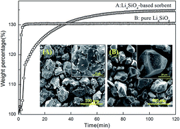
Fig. 3 shows the CO2 sorption isotherms of H6-LS800 and P-LS at 700 °C for 120 min, the CO2 capacity increased with the time. H6-LS800 reached to a maximum adsorption capacity 34.75 wt% after 2 h, while that of P-LS was 30.49 wt%. Then the adsorption kinetics of CO2 on H6-LS800 and P-LS was studied by considering double exponential model:

 
y = A[thin space (1/6-em)]expk1x + B[thin space (1/6-em)]expk2x + C (2)
where y is the weight percentage of CO2 absorbed, x is time, A, B and C are the pre-exponential factors. k1, k2 is the chemisorption constant and diffusion constant, respectively. As Li4SiO4 took place by two different processes, the chemisorption and the lithium diffusion. Lithium located on the surface of Li4SiO4 particles first reacted with CO2, and produced a Li2CO3 external shield (k1), then lithium and oxygen diffusion (k2) which went across external shield to react with CO2 controlled the chemisorption kinetics, when the external layer was completely formed. Table 2 shows the kinetic parameters obtained from the isotherms of the two samples, H6-LS800 more fits the double exponential model. k1 of H6-LS800 is 1 order of magnitude higher than k2, implying that the lithium diffusion is the limiting step during the adsorption process. However, k1 and k2 values of P-LS are high than those of H6-LS800, which may be due to the different materials preparation. P-LS only took 5–8 min to reach 95% of maximum adsorbed amount in Fig. 3, faster than H6-LS800. In such fast time, the Li2CO3 external shield was formed too quickly, which led to the less of lithium and oxygen diffusion.


image file: c6ra05004b-f3.tif
Fig. 3 Isotherms of CO2 sorption on P-LS, H6-LS800 and corresponding fit double exponential model.
Table 2 Kinetic parameters obtained from the isotherms at 700 °C fitted to a double exponential model
Sample k1 k2 R2
H6-LS800 0.214 0.036 0.990
P-LS 0.620 0.621 0.878


A crucial issue for an adsorbent is its chemical stability during the regeneration process. From the experimental results presented above, the most promising sorbent among those compared is the sample H6-LS800, so the regeneration properties and the thermal stability after 10 cycles of this sample was assessed. The test was carried out at a fixed temperature (700 °C) in a Netzsch TG analyzer, the uptake conditions in a CO2 atmosphere (60 min) and the desorption conditions in a N2 atmosphere (60 min) during the test. The adsorption–desorption performance of H6-LS800 indicated that the adsorption capacity increased firstly from 28.74 wt% to 31.99 wt% after the 3rd cycle (Fig. 4). Then the capacity decreased for several cycles and to 28.9 wt% after 10th cycle. The CO2 chemisorption capacity varied in a small area range with the increase of cycle number. The stability of this sorbent showed excellent cyclic adsorption stability, indicating that the sorbent could have interesting potential as a kind of materials for high temperature CO2 capture.


image file: c6ra05004b-f4.tif
Fig. 4 CO2 chemisorption capacities of H6-LS800 as a function of the cycle number during the multiple sorption–desorption cycles.

As was previously mentioned, Li4SiO4 is a promising CO2 absorbent material. Moreover, H6-LS800 sorbents from halloysite showed an enhancing CO2 absorption compared with P-LS. In order to elucidate this enhancement effects, the CO2 adsorption behavior of H6-LS800 was discussed. After Li4SiO4-based sorbent was characterized by XRF and XRD, the metal impurities, such as Al, Zn et al. still existed in the H6-LS800 sorbents (Table 1), which did not modify the XRD patterns of the Li4SiO4-based phase (Fig. 1), but XRD patterns showed some profile changes compared with P-LS, (200) and (002) crystal planes both moved a little to the left (Fig. 5), which indicated that the crystalline structure has been slightly expanded. Ortiz-Landeros et al.20 synthesized the lithium orthosilicate solid solutions: Li4+x(Si1−xAlx)O4 and Li4−x(Si1−xVx)O4, and noted that both aluminum and vanadium ions occupied silicon sites into the Li4SiO4 lattice and the dissolution of aluminum was compensated by Li+ insertion, the dissolution of vanadium led to the lithium vacancies formation, the doping Li4SiO4 with aluminum and vanadium caused the expanded crystalline structures and the shift of the diffraction peaks. Such results were also observed in the H6-LS800, Al3+ (0.039 nm) and Zn (0.135 nm) possessed larger ionic radii than Si4+ (0.026 nm), which was contributed to the cell expansion. The levels of Ca, Mg and K content were low; therefore there were other phases in the H6-LS800.


image file: c6ra05004b-f5.tif
Fig. 5 Zoom of the XRD patterns of P-LS and H6-LS800 samples.

A Rietveld refinement analysis was further performed in order to corroborate the XRD results above. The lattice parameters and cell volume obtained showed that the refinements should be considered as acceptable according to the Rwp values in Table 3. The cell parameters of H6-LS800, a, b, c and β is 5.29927, 6.1125, 5.1556 Å and 90.29 deg, respectively, as well as the cell volume (167.06 Å3), show a slight increase compared with P-LS, which indicated the impurities (Al3+, Na+) doping into the Li4SiO4 structure could expand the crystal lattices. Then the morphology of the samples were obtained by SEM (Fig. 6), showing the SEM images of P-LS and H6-LS800 samples, (A) and (B) represent the SEM images of Li4SiO4 obtained by H6, SiO2 as the silicon source, respectively. The H6-LS800 sample presented a particle size average of 50 μm (Fig. 6a). These particles seemed to be the highly sintered agglomerates; this kind of morphology corresponded well with the high temperature used during the thermal treatment. Some holes were observed on their surface from inserted figure. The P-LS sample presented more dense particles (Fig. 6b), with a particle size of around 60 μm, having a polyhedral shape, and the surface became smoother than H6-LS800, there's no any other holes appeared on it. The simple changes on morphology were probably associated with the existence of metal impurities; actually these metals were not completely leached from HNTs. The metal impurities especially aluminate,48 were reported to inhibit the growing of the particles, and the material seemed to have a higher surface area of H6-LS800. To further understand the effect of these metal impurities, the morphologies of H6-LS800 and P-LS after CO2 sorption were given in Fig. 6c and d. Compared with the SEM image of the initial samples, the particles appear more loose and smaller, the surface of H6-LS800 sorbent presents porous structure, which is beneficial to the CO2 diffusion into the interior of sorbent. Wang et al. also studied the effect of potassium and sodium content on the absorption capacity,5 and found that the surface of Li4SiO4-based sample presented loose and porous structure after 15 cycles sorption/desorption processes, which could ensure the good regenerability properties.

Table 3 Rietveld refinement data obtained from P-LS and H6-LS800
Samples Cell parameters (Å) β (deg) Cell volume (Å)3 Rwp
a b c
Ref 5.298 6.102 5.150 90.25 166.5  
P-LS 5.2975 6.1018 5.1504 90.05 166.48 13.15
H6-LS800 5.2993 6.1125 5.1556 90.29 167.06 12.46


image file: c6ra05004b-f6.tif
Fig. 6 SEM image of as-synthesized (a) H6-LS800, (b) P-LS sorbents, and the corresponding the SEM image of (c) H6-LS800, (d) P-LS after CO2 sorption. The rectangle inset shows magnification of corresponding samples.

SEM images showed that the surface of H6-LS800 presented porous structure, indicating that H6-LS800 had more pores and higher surface area, the existence of metal in the H6-LS800 could be the factor for this phenomenon. Fig. 7 compared the pore size distributions and BET surface area of P-LS and H6-LS800. There a peak was located in the range of 0–20 nm. These two samples all showed a low surface area due to the highly sintered in 800 °C. However, the surfaces of two sorbents are 5.029 m2 g−1 and 4.563 m2 g−1, respectively. From the curves of pore size distributions, H6-LS800 also had a small increase compared with P-LS, therefore, the metal in H6-LS800 indeed exerted a certain extent effect on pore size and BET surface area.


image file: c6ra05004b-f7.tif
Fig. 7 Pore size distributions of P-LS and H6-LS800.

It has to be emphasized that H6-LS800 sorbent captured CO2 more efficiently than P-LS. The thermograms of P-LS and H6-LS800 presented similar behavior, P-LS samples were very stable at temperature lower than 450 °C, then began to absorb CO2, finishing around 700 °C with 30.6% maximum absorption, the capability was well agreement with the previously reported. However, H6-LS800, had the aluminum and other mental impurities, showed a significantly improved CO2 absorption of 34.45% CO2 adsorption capacity. The reaction between Li4SiO4 and CO2 was proven to occur at the outer surface of the crystal grain, the ion diffusion of Li+ and O2− contributed to react with CO2 and to form lithium carbonate. Thus, defects in the crystalline Li4SiO4 could improve its reactivity.49 On the one hand, the addition of aluminum and other metal impurities from HNTs formed defects in H6-LS800 samples, and improved ion mobility. On the other hand, the existence of aluminum inhibited the growing of the particles, and the material tended to have a higher surface area. Therefore, the CO2 chemisorption of H6-LS800 was enhanced compared with P-LS. Because aluminum ions could occupy silicon sites into the Li4SiO4 lattice to form Li4SiO4 solid solutions containing aluminum (Li4+x(Si1−xAlx)O4),20 so H6-LS800 sorbents captured CO2 with a reaction as following:

 
Li4+x(Si1−xAlx)O4 + (1 + x)CO2 → (1 + x)Li2CO3 + (1 − x)Li2SiO3 + xLiAlO2 (3)

Table 4 showed the comparison of the CO2 capture properties of the as-synthesized H6-LS800 sorbent with other Li4SiO4-based sorbents in literature, CO2 chemisorption capacity and temperature ranges were calculated in the process of the sorbents heated from room temperature to 800 °C in 100 vol% CO2 flow. The top half of Table 4, from RHA-Li4SiO4 to IDS-Li4SiO4 sample, showed all kinds of sorbents with different silicon sources, such as rice husk and diatomite. The bottom half indicated some researches on Li4SiO4-based sorbents which were doped with sodium, vanadium and aluminum ions in order to enhance the CO2 adsorb capacity. Compared with diatomite and rice husk as silicon sources, H6-LS800 sample showed an obvious advantage, additionally, H6-LS800 was synthesized by one-step method, which could simplify the doping step of the metal ions.

Table 4 Comparison of CO2 capture properties of as-synthesized samples with the reported materials
Samples Raw materials Synthesis method CO2 chemisorption capacity in 100% CO2 (wt%) CO2 chemisorption temperature ranges (°C) Reference
RHA-Li4SiO4 Rice husk, Li2CO3 Solid-state 32.4 450–710 5
Diatomite-Li4SiO4 Diatomite, Li2CO3 Solid-state 30.32 480–620 11
IDS-Li4SiO4 Diatomite, LiNO3, NH3·H2O Impregnation precipitation 29.89 450–680 15
Li4−xNaxSiO4 TEOS, Li2CO3, Na2CO3 Co-precipitation 19.3 450–680 17
Li4−x(Si1−xVx)O4 SiO2, LiOH, V2O Solid state 4.1 450–680 20
Li4+x(Si1−xAlx)O4 SiO2, LiOH, α-Al2O3 Solid state 17 380–770 20
H6-LS800 Halloysite, Li2CO3 Solid state 34.45 400–720 This work


4. Conclusions

An economical and environmentally friendly Li4SiO4-based sorbent was successfully prepared via solid-state method at 800 °C for 4 h by using natural mineral as silicon sources (H6). The metal impurities especially aluminum from H6 were demonstrated to dope into the structure of Li4SiO4, and the pore volume and surface area of the sorbent were increased. The presence of metals in the sorbent produced an increase of CO2 capacity than pure Li4SiO4. The maximum CO2 adsorption capacity of the sorbent reached up to 34.45%, and the temperature range of CO2 absorption was 350–720 °C. Compared with pure Li4SiO4 prepared by SiO2 as silica source, Li4SiO4-based sorbent not only reduced the cost of synthesis, but also improved the capability of CO2 adsorption. Meanwhile the sorbent exhibited fast kinetics and good stability on ten cycles of CO2 adsorption/desorption performance, indicating a preferential potential material for the higher CO2 quantity and the wider CO2 chemisorption temperature ranges.

Acknowledgements

This work was supported by the National Science Fund for Distinguished Young Scholars (51225403), the National Natural Science Foundation of China (41572036), the State Key Laboratory of Powder Metallurgy, Central South University (2015-19) and the Hunan Provincial Co-Innovation Centre for Clean and Efficient Utilization of Strategic Metal Mineral Resources (2014-405).

Notes and references

  1. Q. Wang, J. Luo and Z. Zhong, Energy Environ. Sci., 2011, 4, 42–55 CAS.
  2. M. Olivares-Marín and M. Maroto-Valer, Greenhouse Gases: Sci. Technol., 2012, 2, 20–35 CrossRef.
  3. S. D. Kenarsari, D. Yang, G. Jiang, S. Zhang, J. Wang, A. G. Russell, Q. Wei and M. Fan, RSC Adv., 2013, 3, 22739 RSC.
  4. H. Yang, Z. Xu, M. Fan, R. Gupta, R. B. Slimane, A. E. Bland and I. Wright, J. Environ. Sci., 2008, 20, 14–17 CrossRef CAS.
  5. K. Wang, X. Guo, P. Zhao, F. Wang and C. Zheng, J. Hazard. Mater., 2011, 189, 301–307 CrossRef CAS PubMed.
  6. A. D. Ebner, S. P. Reynolds and J. A. Ritter, Ind. Eng. Chem. Res., 2006, 45, 6387–6392 CrossRef CAS.
  7. H. R. Radfarnia and M. C. Iliuta, Ind. Eng. Chem. Res., 2012, 51, 10390–10398 CrossRef CAS.
  8. F. Yan, J. Jiang, M. Zhao, S. Tian, K. Li and T. Li, J. Mater. Chem. A, 2015, 3, 7966–7973 CAS.
  9. Y. Duan, H. Pfeiffer, B. Li, I. C. Romero-Ibarra, D. C. Sorescu, D. R. Luebkea and J. W. Halleyd, Phys. Chem. Chem. Phys., 2013, 15, 13538–13558 RSC.
  10. N. Togashi, T. Okumura and K. Oh-ishi, J. Ceram. Soc. Jpn., 2007, 115, 324–328 CrossRef CAS.
  11. S. Shan, Q. Jia, L. Jiang, Q. Li, Y. Wang and J. Peng, Ceram. Int., 2013, 39, 5437–5441 CrossRef CAS.
  12. T. Ávalos-Rendón, V. H. Lara and H. Pfeiffer, Ind. Eng. Chem. Res., 2012, 51, 2622–2630 CrossRef.
  13. X. Yin, M. Song, Q. Zhang and J. Yu, Ind. Eng. Chem. Res., 2010, 49, 6593–6598 CrossRef CAS.
  14. M. Kato, S. Yoshikawa and K. Nakagawa, J. Mater. Sci. Lett., 2002, 21, 485–487 CrossRef CAS.
  15. S. Shan, S. Li, Q. Jia, L. Jiang, Y. Wang and J. Peng, Ind. Eng. Chem. Res., 2013, 52, 6941–6945 CrossRef CAS.
  16. H. Xu, W. Cheng, X. Jin, G. Wang, H. Lu, H. Wang, D. Chen, B. Fan, T. Hou and R. Zhang, Ind. Eng. Chem. Res., 2013, 52, 1886–1891 CrossRef CAS.
  17. V. L. Mejía-Trejo, E. Fregoso-Israel and H. Pfeiffer, Chem. Mater., 2008, 20, 7171–7176 CrossRef.
  18. R. Rodríguez-Mosqueda and H. Pfeiffer, J. Phys. Chem. A, 2010, 114, 4535–4541 CrossRef PubMed.
  19. M. J. Venegas, E. Fregoso-Israel, R. Escamilla and H. Pfeiffer, Ind. Eng. Chem. Res., 2007, 46, 2407–2412 CrossRef CAS.
  20. J. Ortiz-Landeros, C. Gómez-Yáñez, L. M. Palacios-Romero, E. Lima and H. Pfeiffer, J. Phys. Chem. A, 2012, 116, 3163–3171 CrossRef CAS PubMed.
  21. M. Seggiani, M. Puccini and S. Vitolo, Int. J. Greenhouse Gas Control, 2011, 5, 741–748 CrossRef CAS.
  22. M. Seggiani, M. Puccini and S. Vitolo, Int. J. Greenhouse Gas Control, 2013, 17, 25–31 CrossRef CAS.
  23. S. Zhang, Q. Zhang, Y. Ni and Z. Zhu, Int. J. Hydrogen Energy, 2014, 39, 17913–17920 CrossRef CAS.
  24. S. Shan, Q. Jia, L. Jiang, Q. Li, Y. Wang and J. Peng, Chin. Sci. Bull., 2012, 57, 2475–2479 CrossRef CAS.
  25. R. Pacciani, J. Torres, P. Solsona, C. Coe, R. Quinn, J. Hufton, T. Golden and L. F. Vega, Environ. Sci. Technol., 2011, 45, 7083–7088 CrossRef CAS PubMed.
  26. M. Olivares-Marín, T. C. Drage and M. M. Maroto-Valer, Int. J. Greenhouse Gas Control, 2010, 4, 623–629 CrossRef.
  27. S. Liu and H. Yang, Energy Technol., 2015, 3, 77–83 CrossRef CAS.
  28. L. Fu, C. Huo, X. He and H. Yang, RSC Adv., 2015, 5, 20414–20423 RSC.
  29. X. He and H. Yang, Dalton Trans., 2015, 44, 1673–1679 RSC.
  30. J. Jin, L. Fu, H. Yang and J. Ouyang, Sci. Rep., 2015, 5, 12429 CrossRef PubMed.
  31. K. Peng, J. Zhang, H. Yang and J. Ouyang, RSC Adv., 2015, 5, 66134 RSC.
  32. W. Ding, H. Yang and J. Ouyang, RSC Adv., 2015, 5, 67184 RSC.
  33. X. Li, J. Ouyang, Y. Zhou and H. Yang, Sci. Rep., 2015, 5, 13763 CrossRef PubMed.
  34. C. Li, L. Fu, J. Ouyang, A. Tang and H. Yang, Appl. Clay Sci., 2015, 115, 212–220 CrossRef CAS.
  35. K. Peng, L. Fu, H. Yang and J. Ouyang, Sci. Rep., 2016, 6, 19723 CrossRef CAS PubMed.
  36. K. Peng, L. Fu, J. Ouyang and H. Yang, Adv. Funct. Mater., 2016, 26, 2666–2675 CrossRef CAS.
  37. W. Ding, J. Ouyang and H. Yang, Powder Technol., 2016, 292, 169–175 CrossRef CAS.
  38. S. Jana, S. Das, C. Ghosh, A. Maity and M. Pradhan, Sci. Rep., 2015, 5, 8711 CrossRef CAS PubMed.
  39. Y. Xie, A. Tang and H. Yang, Nano, 2015, 10, 1550005 CrossRef CAS.
  40. Y. Zhang, A. Tang, H. Yang and J. Ouyang, Appl. Clay Sci., 2016, 119, 8–17 CrossRef CAS.
  41. Y. M. Lvov, D. G. Shchukin, H. M. Hwald and R. R. Price, ACS Nano, 2008, 2, 814–820 CrossRef CAS PubMed.
  42. G. Cavallaro, G. Lazzara, S. Milioto, G. Palmisano and F. Parisi, J. Colloid Interface Sci., 2014, 417, 66–71 CrossRef CAS PubMed.
  43. G. Cavallaro, G. Lazzara, S. Milioto, F. Parisi and V. Sanzillo, ACS Appl. Mater. Interfaces, 2014, 6, 606–612 CAS.
  44. G. Cavallaro, G. Lazzara, S. Milioto and F. Parisi, Langmuir, 2015, 31, 7472–7478 CrossRef CAS PubMed.
  45. Y. Lvov, A. Aerov and R. Fakhrullin, Adv. Colloid Interface Sci., 2014, 207, 189–198 CrossRef CAS PubMed.
  46. Y. Zhang, L. Fu and H. Yang, Colloids Surf., A, 2012, 414, 115–119 CrossRef CAS.
  47. P. Yuan, D. Tan and F. Annabi-Bergaya, Appl. Clay Sci., 2015, 112–113, 75–93 CrossRef CAS.
  48. B. M. Steenari and O. Lindqvist, Biomass Bioenergy, 1998, 14, 67–76 CrossRef.
  49. C. Gauer and W. Heschel, J. Mater. Sci., 2006, 41, 2405–2409 CrossRef CAS.

This journal is © The Royal Society of Chemistry 2016
Click here to see how this site uses Cookies. View our privacy policy here.