
MOF-derived NixCo1−x(OH)2 composite microspheres for high-performance supercapacitors†
Shuhua Heab,
Zhangpeng Lia,
Jinqing Wang*a,
Ping Wenc,
Jiechang Gaod,
Limin Maa,
Zhigang Yanga and
Shengrong Yang*a
aState Key Laboratory of Solid Lubrication, Lanzhou Institute of Chemical Physics, Chinese Academy of Sciences, Lanzhou 730000, P.R. China. E-mail: jqwang@licp.cas.cn; sryang@licp.cas.cn; Fax: +86 931 8277088; Tel: +86 931 4968076
bUniversity of Chinese Academy of Sciences, Beijing 100080, P.R. China
cDepartment of Chemistry and Chemical Engineering, Baoji University of Arts and Sciences, Baoji, Shanxi 721013, P.R. China
dCollege of Materials Science and Engineering, Lanzhou University of Technology, Lanzhou 730050, P.R. China
First published on 6th May 2016
Abstract
NixCo1−x(OH)2 composite microspheres with uniform sizes are successfully synthesized with the assistance of alkali solution by employing a bimetallic Co–Ni–metal organic framework (Co–Ni–MOF) as both the precursor and the self-sacrificing template. The as-obtained NixCo1−x(OH)2 composite demonstrates excellent electrochemical performance, including a high specific capacitance of 1235.9 F g−1 at a current density of 0.5 A g−1, good electrochemical stability, with ∼73% retention of its initial capacitance after 10![[thin space (1/6-em)]](https://www.rsc.org/images/entities/char_2009.gif) 000 cycles, and a high rate capability; this composite exhibits great application prospects as a novel electrode material for supercapacitors.
000 cycles, and a high rate capability; this composite exhibits great application prospects as a novel electrode material for supercapacitors.
1. Introduction
Due to their attractive features of high power density, long cycle lifetime and stability, rapid recharge ability and environmental benignity, supercapacitors are becoming increasingly important components in energy storage. On the basis of their charge storage mechanisms, supercapacitors can be classified into electrical double-layer capacitors (EDLCs) and pseudocapacitors. Of these, pseudocapacitors exhibit higher specific capacitance and energy density; the study and improvement of the electrode material is one of the key technologies to improve the electrochemical performance of pseudocapacitors.1 Among numerous active electrode materials, metal hydroxides M(OH)2 (M = Co, Ni) have received extensive attention as promising electrode materials for supercapacitors in virtue of their high theoretical capacitance and excellent redox behavior.2–4 To date, numerous methods have been developed to synthesize Ni(OH)2 nanostructures with different morphologies and crystal structures. Unfortunately, Ni(OH)2 is a p-type semiconductor, leading to poor electrical conductivity and rate capability when it is used in electrodes.5,6An efficient strategy to improve the electrochemical performance of metal hydroxides is to introduce other metal ions (such as Al3+, Co2+, Mo2+ and Mn2+) into their textures to form multi-metal compounds. Numerous studies have demonstrated that doping additional metal ions can increase the number of structural defects, improve the conductivity of the composites, and boost redox reactions,5–9 which can dramatically improve the overall electrochemical performance. Based on previously published data,5,6,10,11 it can be concluded that about 16 to 64% improvement of the capacitive performance can be obtained through this strategy.
Very recently, metal–organic frameworks (MOFs), a new class of porous precursors and templates with unique structures and properties, have been used for the synthesis of a variety of functional materials for different applications, such as catalysis, sensors, gas separation and storage, and energy storage. In particular, the applications of MOFs in energy storage and conversion systems, including fuel cells, lithium ion batteries and supercapacitors,12–14 have been widely investigated. Various porous carbons and metal oxides can be obtained easily through direct pyrolysis of MOFs. For example, porous carbon sponges,15,16 Co3O4,17–19 ZnO,20,21 CuO/Cu2O,22 C–Fe3O423 and ZnCo2O424 have been successfully prepared and applied as electrode materials for LIBs and supercapacitors. Compared with other methods, MOF-derived porous carbons and metal oxides have higher surface area and conductivity, as well as unique structures which are favourable to achieving good electrochemical performance. However, MOFs-derived metal hydroxide materials are rarely reported. Recently, Co(OH)2 has been successfully synthesized by Zhang et al.25 using a Co–MOF as a template via a solid–solid conversion process in alkali solution; the compound displayed excellent rate capability and good cycling performance. However, this electrode material displayed lower capacity than expected, greatly limiting its practical applications.
In this paper, we present a simple method to synthesize NixCo1−x(OH)2 composite microspheres via a conformal transformation with the assistance of alkali solution using a bimetallic Co–Ni–metal organic framework (Co–Ni–MOF) as both the precursor and the self-sacrificing template. As far as we know, there are no reports of using bimetallic MOFs to synthesize bimetallic hydroxide materials to date. The as-prepared NixCo1−x(OH)2 composite exhibited high reversible capacity accompanied with good cyclic stability and high rate capability, demonstrating that this hybrid structure can result in improved electrochemical performance of electrodes due to the strong synergistic effects achieved by combining the unique properties of its individual constituents.6–9
2. Experimental section
2.1. Preparations of Co–Ni–MOF, Co–MOF, Ni–MOF and MOF-derived NixCo1−x(OH)2, Co(OH)2 and Ni(OH)2
All chemicals are analytical grade and were used without further purification. In a typical preparation process of Co–Ni–MOF, 2 mmol Co(NO3)2·6H2O, 4 mmol Ni(NO3)2·6H2O and 1.2 g of polyvinylpyrrolidone (PVP, K30) were successively dissolved in 50 mL mixed solvent of N,N-dimethyl-formamide (DMF) and ethanol with a volume ratio of 5:3. After that, 0.6645 g of 1,4-benzenedicarboxylic acid (H2BDC) was added to the obtained mixture solution. The mixture was then stirred and sonicated for 30 min to form a transparent solution. Subsequently, the solution was transferred into a Teflon-lined stainless steel autoclave (90 mL capacity). After sealing, the autoclave was heated to 120 °C for 24 h and cooled naturally to room temperature. Finally, the resulting MOF precipitate was filtered and soaked with ample alcohol to remove residual DMF; then the precipitate was filtered again and dried in an oven at 70 °C overnight. For comparison, Co–MOF and Ni–MOF were also synthesized by a similar procedure to that described for Co–Ni–MOF above, in which 6 mmol Co(NO3)2·6H2O and Ni(NO3)2·6H2O were respectively added.
For synthesis of MOF-derived metal hydroxides, the obtained Co–Ni–MOF, Co–MOF and Ni–MOF precipitates were added to 50 mL KOH (2 M) aqueous solution and stirred at room temperature for 1 h, respectively. Then, the products were soaked with ultrapure water (five times, 250 mL each time) to remove excess KOH and the NixCo1−x(OH)2, Co(OH)2 and Ni(OH)2 materials were obtained, followed by drying in the oven at 70 °C overnight. The inductively coupled plasma atomic emission spectroscopy (ICP-AES) results indicate that the atomic ratio of Ni/Co of NixCo1−x(OH)2 is about 1.64:1. Therefore, the formula of NixCo1−x(OH)2 can be expressed as Ni0.63Co0.37(OH)2.
2.2. Characterization
The structure of the samples was determined by X-ray diffraction (XRD, Rigaku D/Max-2400 diffractometer using Cu-Kα radiation and a graphite monochromator, λ = 1.54056 Å) over the 2θ range from 5° to 80°, Fourier transformation infrared spectroscopy (FTIR, Bruker, IFS66V FTIR spectrometer) and Raman spectroscopy (Renishaw 2000 laser Raman microscope with 514.5 nm line of argon ion laser). The chemical state of the NixCo1−x(OH)2 composites was investigated using an X-ray photoelectron spectrometer (XPS, EscaLab 250Xi) with monochromated Al-Kα irradiation. The metal contents of the samples were determined by ICP-AES (Varian Vista AX CD System). Elemental analysis for C, N, and H were carried out using a Vario EL analyzer. Microstructural characteristics of the composites were observed by a transmission electron microscope (TEM, FEI Tecnai G2 F20) working at 200 kV and a field emission scanning electron microscope (FESEM, JEOL JSM-6701F, Japan) at an acceleration voltage of 5 kV. Thermogravimetric analysis (TGA, STA 449C, Germany) was performed at a scan rate of 10 °C min−1 in the temperature region from 20 to 900 °C under air flow. Nitrogen adsorption–desorption measurements were conducted using a Micromeritics ASAP 2020 apparatus. The specific surface area of the powder samples was determined according to Brunauer–Emmett–Teller (BET) analysis.2.3. Electrochemical measurements
Electrochemical measurements were performed using a CHI 660C electrochemical workstation. The active material (MOF-derived NixCo1−x(OH)2), acetylene black, and poly(tetrafluoroethylene) (PTFE) with a mass ratio of 80:10:10 were mixed to form homogeneous slurry. Then the slurry was pressed into the 1 cm2 nickel foam, dried at 70 °C for 12 h and pressed at 10 MPa. The loading densities of the active materials were about 4 mg cm−2 for all electrodes. Platinum (Pt) foil and Hg/HgO electrodes were applied as the counter and reference electrodes, respectively. All tests were conducted in 6 M KOH electrolyte.
The specific capacitance was calculated from the charge/discharge curves according to the following equation:26
| Cs = IΔt/(mΔV) |
2.4. Fabrication of the asymmetric supercapacitor
The asymmetric supercapacitor was fabricated in 6 M KOH solution using the MOF-derived NixCo1−x(OH)2 as the positive electrode, while activated carbon (AC) was used as the negative electrode. The masses of the positive and negative electrodes were determined according to the specific capacitance calculated from the galvanostatic discharging curves at the same current density in a three-electrode system. The charge balance between the two electrodes will follow the relationship Q+ = Q−. The charge stored (Q) of each electrode can be calculated in terms of the following equation:27| Q = mCΔV |
The energy density E (W h kg−1) and power density P (W kg−1) were calculated as follows:28
| E = 0.5 × C × (ΔV)2 |
| P = E/t |
3. Results and discussion
The FTIR spectra of the as-prepared Co–Ni–MOF and MOF-derived NixCo1−x(OH)2 composites are shown in Fig. 1a. In the FTIR spectrum of Co–Ni–MOF, the bands at 3605 and 1499 cm−1 are respectively associated with the stretching vibrations of OH− and para-aromatic CH groups. The two strong bands at 1584 and 1385 cm−1 are assigned to the asymmetric and symmetric stretching modes of the coordinated (–COO−) group, respectively.29 The difference between these two modes indicated that the –COO− group is coordinated to Ni and Co via a bidentate mode.29,30 After alkali treatment, the characteristic peaks of the organic groups of the Co–Ni–MOF decreased (1584 and 1385 cm−1) or disappeared (3605 and 1499 cm−1). The decreased peaks are attributed to the residue of Co–Ni–MOF in the core of the larger particles.25 The peak at 1652 cm−1 is due to the bending mode of water molecules.31 Additionally, the absorption band centered at 3633 cm−1 is ascribed to the νO–H stretching of the OH groups in the brucite-like structure,31 while the elemental analysis reveals that the mass percentage of C decreases to 6.50% compared with 31.21% in the Co–Ni–MOF, which indicates that the hydroxide ions take the place of carboxyl organic ligands, forming NixCo1−x(OH)2 composite as the result of this transformation.25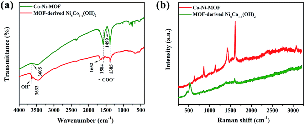 | ||
| Fig. 1 (a) FT-IR spectra and (b) Raman spectra of Co–Ni–MOF and MOF-derived NixCo1−x(OH)2 composite. | ||
The Raman spectra of the Co–Ni–MOF and MOF-derived NixCo1−x(OH)2 composites are exhibited in Fig. 1b. The five strong Raman bands that appeared for Co–Ni–MOF are in accordance with the vibrational finger prints of the benzene ring, which consist of the in-plane (1610, 1425 and 1137 cm−1) and out-of-plane (858 and 627 cm−1) deformation modes of the C–H groups in the BDC2− ligands.32–34 In contrast, in the Raman spectrum of MOF-derived NixCo1−x(OH)2 composite, the intensity of these typical peaks decreases or disappears, coinciding with the FTIR results. In addition, the Raman band located at 465 cm−1 is the typical peak of Ni(OH)2.35,36
To further confirm the above results, XRD measurements of Co–Ni–MOF and MOF-derived NixCo1−x(OH)2 composites were performed, and the results are shown in Fig. 2. The main diffraction peaks of Co–Ni–MOF are consistent with those of Ni–MOF;29,34,37 two obvious diffraction peaks at 8.9° and 16.9° are indexed to the (100) and (101) planes, respectively, accompanied by two weak diffraction peaks at 33° and 42°. For pure Ni–MOF and Co–MOF, the diffraction peaks are similar to that of Co–Ni–MOF (Fig. S2†), indicating that these MOF materials exhibit similar structures. Obviously, the diffraction peaks of MOF-derived NixCo1−x(OH)2 composite are derived from both Ni(OH)2 and Co(OH)2, as confirmed from the standard JCPDS cards no. 14-0117 and no. 30-0443. However, it is difficult to distinguish these two phases because they have similar structures and their diffraction peaks are very close.10,11
 | ||
| Fig. 2 XRD patterns of Co–Ni–MOF and MOF-derived NixCo1−x(OH)2 composite. | ||
The nitrogen adsorption–desorption isotherms and pore size distributions of the samples before and after alkali treatment are shown in Fig. 3, and the related textural parameters are presented in Table 1. The isotherms all exhibit type IV BET characteristics, demonstrating the mesoporous structure of the samples. In contrast, the BET surface area and the total pore volume of the MOF-derived NixCo1−x(OH)2 composite are much higher than those of Co–Ni–MOF, which is because the transformation process occurred from the outside to the inside of particles with the formation of pores.38 The increased surface area and pore volume can provide more buffer space for the volume expansion of the NixCo1−x(OH)2 composite and can permit easy access of electrons and ions to the electrode/electrolyte interface, which is beneficial to enhancing the electrochemical performance.39,40
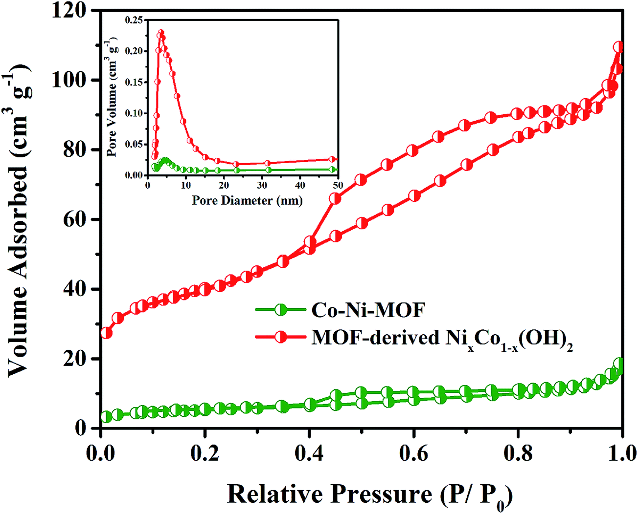 | ||
| Fig. 3 N2 adsorption/desorption isotherm curves of Co–Ni–MOF and MOF-derived NixCo1−x(OH)2 composite at 77 K (inset shows the pore size distribution). | ||
XPS measurements were conducted to acquire further information on the chemical composition of the composite, and the corresponding results are provided in Fig. 4a–c. It can be seen that signals from C, O, Ni and Co elements are detected in the survey spectrum. As shown in Fig. 4b, the two major peaks of Co 2p centered around 797 (Co 2p1/2) and 781 eV (Co 2p3/2) with a spin-energy separation of 16 eV indicated that Co existed in Co(OH)2 form.41,42 In the high resolution Ni 2p spectrum of Fig. 4c, two major peaks with binding energies at 855.8 and 873.6 eV are observed, corresponding to Ni 2p3/2 and Ni 2p1/2, respectively. The spin-energy separation of 17.6 eV is also characteristic of Ni(OH)2, which is in good agreement with previous reports.43,44
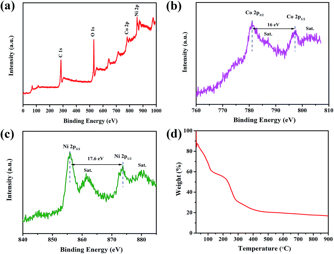 | ||
| Fig. 4 (a) XPS spectrum of the MOF-derived NixCo1−x(OH)2 composite and the elemental spectrum of Co 2p (b) and Ni 2p (c). (d) TG curve of the MOF-derived NixCo1−x(OH)2 composite. | ||
Fig. 4d shows the thermogravimetric (TG) curve of the MOF-derived NixCo1−x(OH)2 composite in air from 20 to 900 °C. The initial weight loss of 40% at around 100 °C is attributed to the desorption of physically adsorbed water, subsequently, the weight loss of 35% occurs in the range of 160 to 400 °C, which may be due to the decomposition of the NixCo1−x(OH)2 composite into the respective oxides, as well as the decomposition of the residual organic ligands.25
The SEM image of the MOF-derived NixCo1−x(OH)2 composite is presented in Fig. 5a. The extensive formation of microspheres with sizes of 400 to 600 nm can be seen; this is in excellent agreement with the observations from the TEM image inserted in Fig. 5a. The morphology was not significantly changed after alkali treatment (Fig. S1†). The HRTEM image in Fig. 5b indicates that the composite has a multiphase structure. The corresponding selected area electron diffraction (SAED) pattern (shown in the inset of Fig. 5b) presents multiple diffraction circles, which can be indexed as the lattice planes of (101) and (110) for Ni(OH)2 as well as the (110) and (200) planes for Co(OH)2, respectively. Furthermore, the nature of the MOF-derived NixCo1−x(OH)2 composite is further elucidated by the mapping analysis of energy-dispersive X-ray spectrometry (EDS) for elements C, O, Co and Ni. As is clearly shown in Fig. 5c, a uniform distribution of C, O, Co and Ni elements throughout the whole grain is observed, which is important for obtaining excellent capacitive performance.34
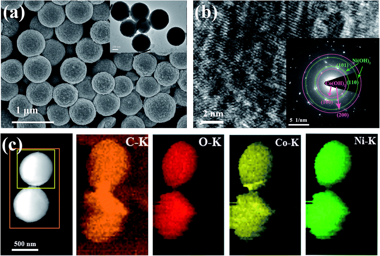 | ||
| Fig. 5 (a) SEM image (inset is the TEM image) and (b) HRTEM image (inset is the selected area electron diffraction pattern) of MOF-derived NixCo1−x(OH)2 composite. (c) TEM image of a selected MOF-derived NixCo1−x(OH)2 composite to be mapped by EDS and EDS mapping results of C, O, Ni, and Co elements. | ||
Cyclic voltammetry (CV) and galvanostatic charge–discharge (GCD) tests were carried out with a three-electrode cell in 6 M KOH electrolyte. To better investigate the electrochemical reactivity of the active materials, the CV curves of the MOF-derived Ni(OH)2 and Co(OH)2 are also given in Fig. 6a for comparison. In the CV curve of MOF-derived Co(OH)2, two pairs of redox peaks can be observed, indicating that reversible pseudocapacitive reactions of Co(OH)2 were involved; the two redox couples can be observed due to the following electrochemical reactions:6,10,45
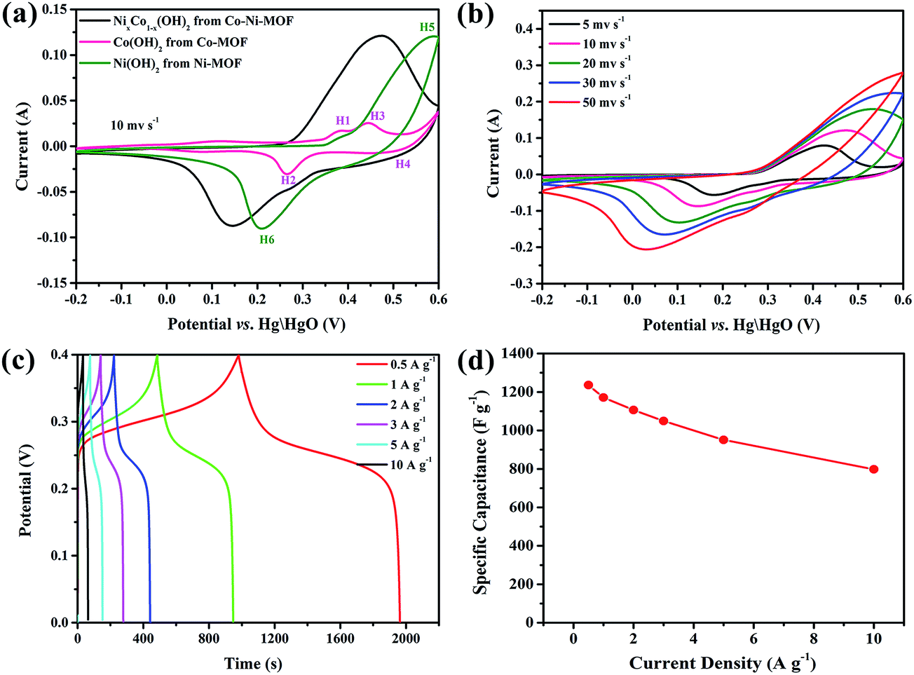 | ||
| Fig. 6 (a) CV curves of the MOF-derived NixCo1−x(OH)2 composite, Ni(OH)2 and Co(OH)2 at a scan rate of 10 mV s−1. (b) CV curves of the MOF-derived NixCo1−x(OH)2 composite in 6 M KOH electrolyte at different scan rates. (c) Galvanostatic charge–discharge (GCD) curves of the MOF-derived NixCo1−x(OH)2 composite at different current densities. (d) The corresponding specific capacitance at current densities from 0.5 to 10 A g−1. | ||
H1 and H2:
| Co(OH)2 + OH− ↔ CoO(OH) + H2O + e− | (1) |
H3 and H4:
| CoO(OH) + OH− ↔ CoO2 + H2O + e− | (2) |
A pair of large redox peaks can be clearly identified in the CV curve of MOF-derived Ni(OH)2, which is governed by the following reversible reaction between Ni(II) and Ni(III):6,10,45
H5 and H6:
| Ni(OH)2 + OH− ↔ NiO(OH) + H2O + e− | (3) |
Compared with the MOF-derived Ni(OH)2 electrode, the oxidation and reduction potentials for the MOF-derived NixCo1−x(OH)2 composite electrode shift remarkably to the negative direction, suggesting that the NixCo1−x(OH)2 composite electrode can be charged more easily,11 which is possibly due to the improved conductivity of the composite. As shown in Fig. S3,† the diameter of the semicircle for the NixCo1−x(OH)2 composites is dramatically smaller than that for pure Ni(OH)2, illustrating that the composite electrodes have lower charge transfer resistance. The diffusion resistance is also lower, as the slope of the low-frequency line is steeper.45,46 These results offer strong evidence that the existence of Co element could increase the conductivity of the composites, which facilitates the electron transfer and the intercalation/deintercalation of electrolyte ions.7,8 Moreover, the CV curve area of the NixCo1−x(OH)2 composite is larger than those of MOF-derived Ni(OH)2 and Co(OH)2, which further confirms that Co(OH)2 contributes some capacitance to the composite electrode.
Fig. 6b shows the CV curves for the MOF-derived NixCo1−x(OH)2 composite at various scan rates. It is apparent that the CV curve area and the peak current increase with increasing scan rate. The symmetric characteristic of the anodic and cathodic peaks reveals the excellent reversibility of the MOF-derived NixCo1−x(OH)2 composite electrode. Additionally, the oxidation and reduction peaks shift to higher and lower potentials, respectively, which can be ascribed to the increment of the internal diffusion resistance and weak polarization of the electrodes.43
In order to estimate the electrochemical capacitance of the materials, the galvanostatic charge–discharge curves of the composite electrodes at various current densities are presented in Fig. 6c. It can be seen that all the curves have one pair of obvious charge and discharge plateaus, resulting from the typically faradaic reactions of the composite. The specific capacitances of NixCo1−x(OH)2 composite are 1235.9, 1171.1, 1106.1, 1048.8 and 951.3 F g−1 at different discharge current densities of 0.5, 1, 2, 3, and 5 A g−1, respectively. In addition, these values are much higher than reported values in the literature, such as Ni(OH)2@Co(OH)2 nanohexagons prepared via a mild wet chemical approach (312 F g−1 at a current density of 1 A g−1, reported by Wang et al.47), Co(OH)2/Ni(OH)2 composite prepared via mixing as-synthesized Co(OH)2 and Ni(OH)2 in different proportions (delivers a maximum capacitance of 226 F g−1 at 2 A g−1, reported by Su et al.48) and NiCoAl-layered double hydroxide nanosheets via a facile yet simple urea precipitation method (839 F g−1 at 2 A g−1, reported by Qiu et al.9). Moreover, this composite also exhibits good rate capability; 64.6% of the capacitance is retained when the discharge current density is increased from 0.5 to 10 A g−1. This further verifies the contribution of strong synergistic effects in enhancing the specific capacitance of the NixCo1−x(OH)2 composite. Additionally, the increased surface area and pore volume can provide more buffer space for the volume expansion of the composite, enlarge the contact of the electrode and the electrolyte, and permit easy access of electrons and ions to the electrode/electrolyte interface,39,40 which is beneficial to the enhancement of the electrochemical performance.
To further investigate the MOF-derived NixCo1−x(OH)2 composite electrode for practical applications, an asymmetric supercapacitor was fabricated in 6 M KOH using the MOF-derived NixCo1−x(OH)2 as the positive electrode, while activated carbon (AC) was used as the negative electrode. Fig. 7a presents the typical CV curves of the positive and negative electrodes, recorded at a scan rate of 50 mV s−1 in a three-electrode system. The MOF-derived NixCo1−x(OH)2 electrode can be operated within a potential window of −0.2 to 0.6 V, and its CV curve exhibits a pseudocapacitance behavior; meanwhile, the AC electrode can be operated within a potential window of −1 to 0 V and the rectangular shaped CV curve presents an electric double layer capacitance.
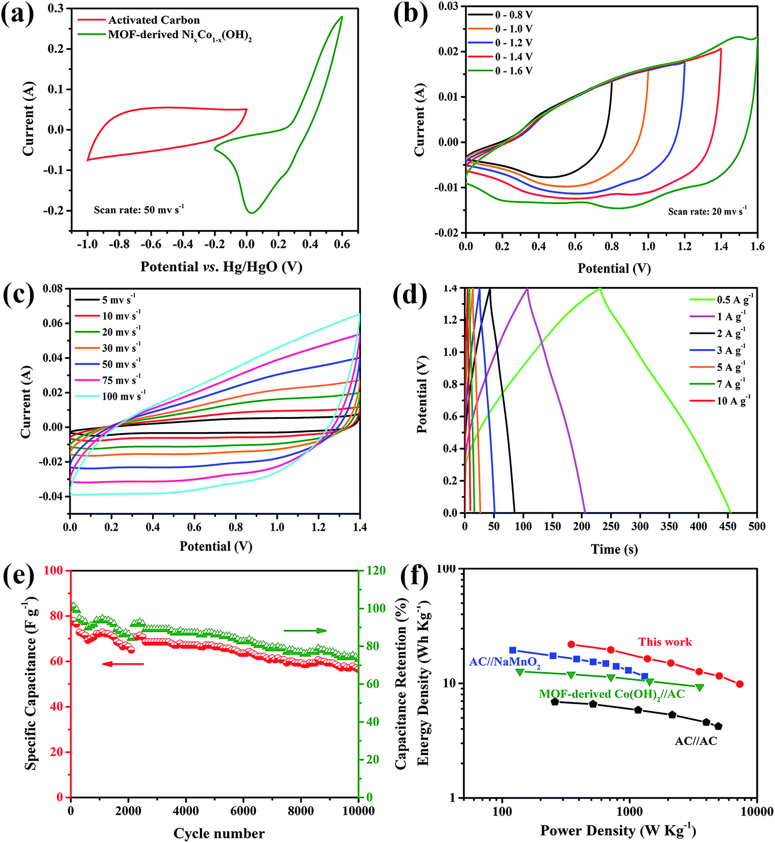 | ||
| Fig. 7 (a) CV curves of AC and the MOF-derived NixCo1−x(OH)2 composite electrodes at a scan rate of 50 mV s−1, respectively. (b and c) CV curves of the MOF-derived NixCo1−x(OH)2//AC asymmetric supercapacitor device at different voltage windows and different scan rates. (d) Charge–discharge curves of the MOF-derived NixCo1−x(OH)2//AC device at different current densities. (e) Cycling performances of the MOF-derived NixCo1−x(OH)2//AC asymmetric supercapacitor device at a current density of 1 A g−1. (f) Ragone plots of the MOF-derived NixCo1−x(OH)2//AC device. | ||
Fig. 7b shows CV curves of the MOF-derived NixCo1−x(OH)2//AC asymmetric supercapacitor device at different voltage windows from 0.8 to 1.6 V at a scan rate of 20 mV s−1, confirming that the asymmetric supercapacitor device can function at a high voltage of 1.6 V. Fig. 7c shows the CV curves of the assembled two-electrode asymmetric supercapacitor with scan rates ranging from 5 to 100 mV s−1. It can be seen that the CV curve is well preserved even at a scan rate as high as 100 mV s−1, suggesting the excellent rate capability of the asymmetric supercapacitor.
Galvanostatic charge–discharge curves of the asymmetric supercapacitor device at a series of current densities are demonstrated in Fig. 7d. At different discharge current densities of 0.5, 1, 2, 3, and 5 A g−1, the calculated specific capacitances of this asymmetric supercapacitor are 80.3, 71.8, 60.1, 55.1 and 46.4 F g−1, respectively.
As shown in Fig. 7e, the cycling stability of this asymmetric supercapacitor device was also evaluated, indicating that a good electrochemical stability with ∼73% retention of its initial capacitance can be obtained after 10000 cycles. Based on the calculated capacitance values, the asymmetric supercapacitor can deliver a maximum energy density of 21.9 W h kg−1 at a power density of 348.9 W kg−1. As summarized in Fig. 7f, the obtained energy density and power density value in this work are comparable to or higher than those of recently reported asymmetric supercapacitors25,49 and AC//AC symmetrical supercapacitors (<10 W h kg−1).50,51 As a result, all of these properties make the MOF-derived NixCo1−x(OH)2//AC asymmetric supercapacitor a promising candidate for future energy storage applications in electric vehicles and hybrid electric vehicles.
4. Conclusions
In summary, NixCo1−x(OH)2 composite microspheres with superior electrochemical performance were synthesized using MOF as both the precursor and the self-sacrificing template. The presence of Co(OH)2 effectively improves the conductivity of the Ni(OH)2 particles and contributes some capacitance to the composite electrode. After alkali treatment, the dramatically increased surface area and pore volume provide more buffer space for the volume expansion of the NixCo1−x(OH)2 composite in the charging/discharging processes, permitting easy access of electrons and ions to the electrode/electrolyte interface. The as-obtained NixCo1−x(OH)2 composite presented a high specific capacitance of 1235.9 F g−1 at a current density of 0.5 A g−1 as well as good electrochemical stability, with ∼73% retention of its initial capacitance after 10000 cycles, demonstrating superior long term electrochemical stability. In addition, this preparative method can be a universal chemistry approach to the synthesis of other metal hydroxide materials.
Acknowledgements
This work was supported by the National Natural Science Foundation of China (Grant No. 51502306).References
- G. Wang, L. Zhang and J. Zhang, Chem. Soc. Rev., 2012, 41, 797–828 RSC.
- R. Kötz and M. Carlen, Electrochim. Acta, 2000, 45, 2483–2498 CrossRef.
- A. Burke, J. Power Sources, 2000, 91, 37–50 CrossRef CAS.
- M. Winter and R. J. Brodd, Chem. Rev., 2004, 104, 4245–4269 CrossRef CAS PubMed.
- X. Chen, C. Long, C. Lin, T. Wei, J. Yan, L. Jiang and Z. Fan, Electrochim. Acta, 2014, 137, 352–358 CrossRef CAS.
- J. X. Li, M. Yang, J. P. Wei and Z. Zhou, Nanoscale, 2012, 4, 4498–4503 RSC.
- R. Wang and X. Yan, Sci. Rep., 2014, 4, 3712 Search PubMed.
- Q. Wang, S. Liu, H. Sun and Q. Lu, RSC Adv., 2015, 5, 48181–48186 RSC.
- J. Yang, C. Yu, X. Fan, Z. Ling, J. Qiu and Y. Gogotsi, J. Mater. Chem. A, 2013, 1, 1963–1968 CAS.
- M. Li, S. Xu, Y. Zhu, P. Yang, L. Wang and P. K. Chu, J. Alloys Compd., 2014, 589, 364–371 CrossRef CAS.
- J. Xu, Y. Dong, J. Cao, B. Guo, W. Wang and Z. Chen, Electrochim. Acta, 2013, 114, 76–82 CrossRef CAS.
- Q. L. Zhu and Q. Xu, Chem. Soc. Rev., 2014, 43, 5468–5512 RSC.
- L. Lux, K. Williams and S. Ma, CrystEngComm, 2015, 17, 10–22 RSC.
- F. Ke, Y. Wu and H. Deng, J. Solid State Chem., 2015, 223, 109–121 CrossRef CAS.
- Z. Li and L. Yin, Nanoscale, 2015, 7, 9597–9606 RSC.
- X. Yan, X. Li, Z. Yan and S. Komarneni, Appl. Surf. Sci., 2014, 308, 306–310 CrossRef CAS.
- C. Li, T. Chen, W. Xu, X. Lou, L. Pan, Q. Chen and B. Hu, J. Mater. Chem. A, 2015, 3, 5585–5591 CAS.
- J. Shao, Z. Wan, H. Liu, H. Zheng, T. Gao, M. Shen, Q. Qu and H. Zheng, J. Mater. Chem. A, 2014, 2, 12194–12200 CAS.
- X. Li, Y. Fang, X. Lin, M. Tian, X. An, Y. Fu, R. Li, J. Jin and J. Ma, J. Mater. Chem. A, 2015, 3, 17392–17402 CAS.
- G. Zhang, S. Hou, H. Zhang, W. Zeng, F. Yan, C. C. Li and H. Duan, Adv. Mater., 2015, 27, 2400–2405 CrossRef CAS PubMed.
- H. Yue, Z. Shi, Q. Wang, Z. Cao, H. Dong, Y. Qiao, Y. Yin and S. Yang, ACS Appl. Mater. Interfaces, 2014, 6, 17067–17074 CAS.
- X. Zhang, W. Qin, D. Li, D. Yan, B. Hu, Z. Sun and L. Pan, Chem. Commun., 2015, 51, 16413–16416 RSC.
- M. Li, W. Wang, M. Yang, F. Lv, L. Cao, Y. Tang, R. Sun and Z. Lu, RSC Adv., 2015, 5, 7356–7362 RSC.
- S. Chen, M. Xue, Y. Li, Y. Pan, L. Zhu, D. Zhang, Q. Fang and S. Qiu, Inorg. Chem. Front., 2015, 2, 177–183 RSC.
- Z. Wang, Y. Liu, C. Gao, H. Jiang and J. Zhang, J. Mater. Chem. A, 2015, 3, 20658–20663 CAS.
- J. Liu, J. Jiang, C. Cheng, H. Li, J. Zhang, H. Gong and H. J. Fan, Adv. Mater., 2011, 23, 2076–2081 CrossRef CAS PubMed.
- W. Hong, J. Wang, P. Gong, J. Sun, L. Niu, Z. Yang, Z. Wang and S. Yang, J. Power Sources, 2014, 270, 516–525 CrossRef CAS.
- M. Liu, L. Kong, C. Lu, X. Ma, X. Li, Y. Luo and L. Kang, J. Mater. Chem. A, 2013, 1, 1380–1387 CAS.
- J. Yang, P. Xiong, C. Zheng, H. Qiu and M. Wei, J. Mater. Chem. A, 2014, 2, 16640–16644 CAS.
- A. Mesbah, P. Rabu, R. Sibille, S. Lebegue, T. Mazet, B. Malaman and M. Francois, Inorg. Chem., 2014, 53, 872–881 CrossRef CAS PubMed.
- A. A. Malek Barmi, M. Aghazadeh, B. Arhami, H. M. Shiri, A. A. Fazl and E. Jangju, Chem. Phys. Lett., 2012, 541, 65–69 CrossRef CAS.
- S. Bordiga, C. Lamberti, G. Ricchiardi, L. Regli, F. Bonino, A. Damin, K. P. Lillerud, M. Bjorgen and A. Zecchina, Chem. Commun., 2004, 2300–2301 RSC.
- Y. H. Hu and L. Zhang, Phys. Rev. B: Condens. Matter Mater. Phys., 2010, 81, 174103 CrossRef.
- P. Wen, P. Gong, J. Sun, J. Wang and S. Yang, J. Mater. Chem. A, 2015, 3, 13874–13883 CAS.
- B. Li, M. Ai and Z. Xu, Chem. Commun., 2010, 46, 6267–6269 RSC.
- X. Dai, D. Chen, H. Fan, Y. Zhong, L. Chang, H. Shao, J. Wang, J. Zhang and C. N. Cao, Electrochim. Acta, 2015, 154, 128–135 CrossRef CAS.
- J. Yang, C. Zheng, P. Xiong, Y. Li and M. Wei, J. Mater. Chem. A, 2014, 2, 19005–19010 CAS.
- D. O. Miles, D. Jiang, A. D. Burrows, J. E. Halls and F. Marken, Electrochem. Commun., 2013, 27, 9–13 CrossRef CAS.
- D. Wang, F. Li and H. Cheng, J. Power Sources, 2008, 185, 1563–1568 CrossRef CAS.
- Y. Chen, Y. Liu and W. Yan, J. Mater. Chem. A, 2014, 2, 5903–5909 CAS.
- J. Chang, C. Wu and I. W. Sun, J. Mater. Chem., 2010, 20, 3729–3735 RSC.
- C. Chen, M. Cho and Y. Lee, J. Mater. Sci., 2015, 50, 6491–6497 CrossRef CAS.
- J. Yan, Z. Fan, W. Sun, G. Ning, T. Wei, Q. Zhang, R. Zhang, L. Zhi and F. Wei, Adv. Funct. Mater., 2012, 22, 2632–2641 CrossRef CAS.
- J. W. Lee, T. Ahn, D. Soundararajan, J. M. Ko and J. D. Kim, Chem. Commun., 2011, 47, 6305–6307 RSC.
- D. P. Dubal, G. S. Gund, C. D. Lokhande and R. Holze, ACS Appl. Mater. Interfaces, 2013, 5, 2446–2454 CAS.
- Y. Wang, B. Chang, D. Guan, K. Pei, Z. Chen, M. Yang and X. Dong, Mater. Lett., 2014, 135, 172–175 CrossRef CAS.
- D. Zhou, X. Su, M. Boese, R. Wang and H. Zhang, Nano Energy, 2014, 5, 52–59 CrossRef CAS.
- L. Su, L. Gong and J. Gao, J. Power Sources, 2012, 209, 141–146 CrossRef CAS.
- Q. T. Qu, Y. Shi, S. Tian, Y. H. Chen, Y. P. Wu and R. Holze, J. Power Sources, 2009, 194, 1222–1225 CrossRef CAS.
- R. Wang, X. Yan, J. Lang, Z. Zheng and P. Zhang, J. Mater. Chem. A, 2014, 2, 12724–12732 CAS.
- C. Zheng, L. Qi, M. Yoshio and H. Wang, J. Power Sources, 2010, 195, 4406–4409 CrossRef CAS.
Footnote |
| † Electronic supplementary information (ESI) available. See DOI: 10.1039/c6ra03992h |
| This journal is © The Royal Society of Chemistry 2016 |