DOI:
10.1039/C6RA03912J
(Paper)
RSC Adv., 2016,
6, 30106-30114
Carbon nanotube/polyimide bilayer thin films with high structural stability, optical transparency, and electric heating performance
Received
12th February 2016
, Accepted 16th March 2016
First published on 17th March 2016
Abstract
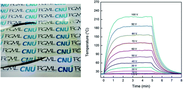
Structurally stable and optically transparent multiwalled carbon nanotube/polyimide (MWCNT/PI) bilayer thin films with different MWCNT thicknesses of 56–155 nm are manufactured by a facile spin-coating of MWCNT aqueous solution and poly(amic acid) (PAA) solution on a glass substrate, followed by thermal treatment for imidization. For this purpose, PAA as a PI precursor is synthesized by the reaction of pyromellitic dianhydride and 4,4′-diaminodiphenylether. The MWCNT layer thickness in the bilayer films is controlled by the cycle number of the spin-coating process of the MWCNT aqueous solution on the glass substrate. SEM images of the bilayer films reveal that neat MWCNT layers are uniformly coated on glass substrates and they are covered well with a PI layer. Accordingly, the MWCNT/PI bilayer films are mechanically and structurally stable owing to the presence of a PI layer on the MWCNT layer, compared to neat MWCNT films on glass substrates. With the increase of the MWCNT layer thickness in the bilayer films from 56 nm to 155 nm, the sheet resistance decreases from ∼1.97 × 10⁵ Ω sq−1 to ∼3.89 × 10³ Ω sq−1 and the optical transparency at 550 nm wavelength also decreases from ∼78% to ∼52%. The MWCNT/PI bilayer thin films exhibit a high electric heating performance in view of the rapid heating/cooling response time of 13.8–16.8 s, high electric power efficiency of 11.5–14.8 mW per °C, and high steady-state maximum temperatures up to 219 °C as a function of the applied voltage of 20–100 V.
1. Introduction
Transparent conductive films are crucial components of optoelectronic devices, including flat panel displays, touch screens, light-emitting diodes, heaters, and solar cells.1–3 Since the discovery of carbon nanotubes (CNTs), they have been widely chosen as transparent conductive thin film materials due to their outstanding electrical properties such as the high electrical conductivity of 104 to 105 S cm−1 and carrier mobility of 1000–4000 cm2 V−1 s−1, in addition to exceptional mechanical and thermal properties such as Young's modulus of 0.27–1.25 TPa, thermal conductivity of 3000–6600 W m−1 K−1, and thermal stability up to ∼700 °C in air.4–7 A variety of dry and wet processes have been developed for manufacturing transparent and conductive CNT films.8–10 Dry processes for CNT thin films include chemical vapor deposition, transfer-printing, pulling from vertically grown CNT forest, etc.11–14 Multiple approaches have been also used for wet processes, such as drop-casting, spin-coating, rod-coating, spray-coating, dip-coating, Langmuir–Blodgett technique, inkjet printing, vacuum filtration, and electrophoretic deposition.15–19 Especially, spin-coating, which is one of the most common techniques for applying CNT thin films to substrates, is used in a wide variety of industries and technology sectors in electronics and nanotechnology.20,21 One advantage of the spin-coating is the ability to quickly and easily produce very uniform films from a few nanometers to microns in thickness.
Recently, transparent and conductive CNT thin films have been investigated as electric heating elements or devices that prevent automobiles and windows from fogging or icing.22–24 Yoon et al. fabricated single-walled CNT (SWCNT) films by a vacuum filtration method, and transferred the films to glass or PET substrates.22 The electric heating capability of the SWCNT films with a sheet resistance of 1190 Ω sq−1 and a transparency of 91.3% was proved to be better than existing Ag films by consuming much less electric power to attain a target temperature. Jang et al. prepared a transparent multiwalled CNT (MWCNT) sheet by pulling from vertically-aligned MWCNT forest, and then directly placed the sheet on a PET film or glass substrate to produce single and double MWCNT sheets with sheet resistances of ∼699 Ω sq−1 and ∼349 Ω sq−1 and transmittances of 81–85% and 67–72%, respectively.23 Both MWCNT sheet films as flexible and transparent heaters showed rapid thermal responses and uniform temperature distribution, when heated by applying a direct current. Kang et al. also investigated the electric heating behavior of SWCNT films with different thicknesses on a glass substrate, which were manufactured by a dip-coating method.24 Although previous reports on transparent conductive CNT films exhibited good electric heating performance, their surfaces could be damaged by external mechanical stimuli. The protection of the surfaces is prerequisite for the practical applications of the transparent CNT films as electric film heaters.
In the present study, we have adopted polyimide (PI) as a protection layer material for the transparent MWCNT-based film heaters, since PIs are well known to have high thermal resistance, chemical resistance, dimensional stability, dielectric strength, mechanical strength, and optical transparency.25–30 For the first time, we have manufactured a series of structurally stable and transparent MWCNT/PI bilayer films with different MWCNT layer thicknesses of 56–155 nm as high performance electric film heaters by using a simple and efficient spin-coating of MWCNT aqueous solution and PI precursor solution on a glass substrate, and following thermal treatment for imidization. For the PI precursor, poly(amic acid) (PAA) was synthesized from pyromellitic dianhydride and 4,4′-diaminodiphenylether. The microstructure, optical transparency, and electrical property of the MWCNT/PI bilayer thin films on glass substrates are systematically investigated as a function of the MWCNT layer thickness with aids of scanning electron microscope, UV-vis spectrometer, and multiple electrometers, respectively. For comparison, neat MWCNT thin films on glass substrates are prepared, and their structural and physical properties are also characterized. The electric heating behavior of the neat MWCNT films and MWCNT/PI bilayer thin films on glass substrates is analyzed by taking into account applied voltage-dependent steady-state maximum temperatures, temperature response rapidity, and electric power efficiency.
2. Experimental part
2.1. Materials
Pyromellitic dianhydride (PMDA, >98.0%, TCI) and 4,4′-diaminodiphenylether (4,4′-ODA, >98.0%, TCI) were used as monomers for synthesizing poly(amic acid) (PAA) as the PI precursor. N,N′-dimethylacetamide (DMAc, 99.5%, Samchun Chemicals) and γ-butyrolactone (GBL, 99.0%, Samchun Chemicals) were adopted as solvents for the solution polymerization of PAA. Pristine MWCNT (CM-250) with 10–15 nm diameter and 100 μm length, produced by thermal chemical vapor deposition, was purchased from Hanwha Chemical. Sodium dodecylbenzene sulfonate (SDBS, Tech, Aldrich Chemistry Com.) was used as a surfactant to disperse MWCNT in deionized water. All the materials and chemicals were used as received without specific purification.
2.2. Preparation of the bilayer thin films
PAA was synthesized via the reaction between 4,4′-ODA and PMDA in a mixed solvent of DMAc and GBL (50/50 by wt%). Equal molar amount of 4,4′-ODA (25.030 g) and PMDA (27.265 g) was dissolved completely in the mixed solvent and the polymerization was carried out at room temperature for 2 h with mechanical stirring under nitrogen atmosphere. After the solution polymerization, the concentration of PAA in the solvent was controlled to be 5.0 wt% for an efficient and uniform spin-coating. Since GBL as a good solvent for PAA has low miscibility with water, compared to DMAc, the mixed solvent of DMAc and GBL was used to minimize the water-induced decomposition during the synthesis, storage, and spin-coating process of PAA.
To prepare an MWCNT aqueous solution, 0.25 wt% MWCNT and 0.25 wt% SDBS were added into deionized water and then mixed with a horn-type ultrasonicator (Vibra Cell 505, Sonics and materials Inc.) for 40 min. The MWCNT aqueous solution of 1 mL was applied on a glass substrate (25.4 mm × 76.2 mm) and spin-coated with a two-step procedure of 500 rpm for 10 s and 2000 rpm for 10 s by using a spin-coater (SF-100NA, Won Corporation). The thickness of the MWCNT thin films on the glass substrate was controlled by the cycle number of the spin-coating process for the MWCNT aqueous solution, which was 1 to 5 times. The MWCNT thin films on glass substrates were named as MWCNTx, where x denotes the thickness of MWCNT layers in nanometer. To manufacture MWCNT/PAA bilayer films, 2 mL PAA solution was applied on the neat MWCNT films for spin-coating and dried at 70 °C for 30 min on a hot plate. Finally, MWCNT/PI bilayer thin films were obtained by a thermal treatment of the MWCNT/PAA bilayer films on glass substrates in a vacuum oven at 400 °C for 5 min. The bilayer thin films were named as MWCNTx/PI. The overall procedure to manufacture the neat MWCNT and MWCNT/PI bilayer thin films on glass substrates was presented schematically in Fig. 1.
 |
| Fig. 1 Schematic procedure to manufacture neat MWCNT films and MWCNT/PI bilayer thin films. | |
2.3. Characterization
The surface and cross-section morphologies of the neat MWCNT films and MWCNT/PI bilayer thin films on glass substrates were examined by using a cold-type field emission scanning electron microscope (SEM, S-4800, Hitachi). To obtain the SEM images, the film samples were coated with osmium conductive metal. The optical transmittance of the film samples on glass substrates was identified quantitatively by using a UV-visible spectrometer (S-3100, SCINCO). The thermal properties of PAA and PI films were investigated by using a differential scanning calorimeter (DSC-6000, Perkin Elmer) and a thermogravimetric analyzer (TGA-4000, Perkin Elmer) under nitrogen atmosphere at a heating rate of 10 °C min−1. The chemical transformation from PAA to PI via the thermal treatment at 400 °C for 5 min was identified by FT-IR spectroscopy (iS10, Thermo scientific Inc.). To characterize the structural stability of the MWCNT films and MWCNT/PI bilayer films on glass substrates, the adhesion test was performed using a commercially available Scotch Magic tape (3M). The voltage-dependent electrical current and electric power of the MWCNT films and MWCNT/PI bilayer films with different MWCNT layer thickness were measured by using multiple sourcemeter and nanovoltmeter (2400, 2182A, Keithley Instruments). The electric heating behavior of the neat MWCNT and MWCNT/PI bilayer thin films under different applied voltages of 1–100 V was characterized with an infrared camera (SE/A325, FTIR Systems) and a sourcemeter (2400, Keithley Instruments). For the electrical experiments, the distance between electrodes on the film samples with 10.0 mm width and 25.0 mm length was set to be 20.0 mm.
3. Results and discussion
3.1. Morphology and optical transparency
To confirm the successful chemical transformation of PAA to PI by the thermal treatment, FT-IR spectra of PAA and PI films were obtained, as shown in Fig. 2. In the FT-IR spectrum of PAA film, typical vibrational bands related with amide and carboxylic acid groups are observed at 1500–1800 cm−1. In detail, the bands at 1538 and 1652 cm−1 are assigned to C–N stretching and C
O stretching vibration modes of amide functional groups, respectively, and the band at 1714 cm−1 is related with the C
O stretching mode of carboxylic acid group in the PAA backbone.31 On the other hand, in case of the FT-IR spectrum of the PI film, new bands associated with C
O asymmetric stretching, C
O symmetric stretching, C–N stretching, and C
O bending vibrational modes were detected at 1776, 1716, 1371, and 719 cm−1, respectively, in addition to the disappearance of the bands at 1538 and 1652 cm−1 of the PAA film.31 From the DSC and TGA thermograms in Fig. 3, it is confirmed that the thermal imidization, which is endothermic and accompanied by the removal of water molecules, takes place in a broad temperature range of 125–300 °C. The PI film, which was obtained by the thermal treatment of the PAA film at 400 °C for 5 min, is found to be thermally stable up to ∼550 °C without showing any thermal transition and weight loss, as can be seen in DSC and TGA curves of Fig. 3. These results demonstrate the complete chemical transformation from PAA to PI via the thermal imidization at 400 °C and 5 min.
 |
| Fig. 2 FT-IR spectra of PAA and PI films, where the PI film was prepared by the thermal treatment of a PAA film at 400 °C for 5 min. | |
 |
| Fig. 3 (A) DSC and (B) TGA thermograms of PAA and PI films, where the PI film was prepared by the thermal treatment of a PAA film at 400 °C for 5 min. | |
The microstructures of the surface and cross-section for the neat MWCNT films and MWCNT/PI bilayer thin films on glass substrates were examined using a cold-type FE-SEM. The thicknesses of the neat MWCNT films on glass substrates were measured from the cross-section SEM images. As a result, the thickness was found to increase linearly from 56 nm to 155 nm with the increase of the cycle number of spin-coating process from 2 to 5, as shown in Fig. 4. A representative SEM image of the cross-section of the neat MWCNT film on a glass substrate, which was manufactured by twice spin-coating, was inserted in Fig. 4.
 |
| Fig. 4 Change of average thickness of MWCNT layers as a function of the cycle number of spin-coating. Inset shows a typical SEM image of cross-section of neat MWCNT film on a glass substrate, which was prepared by twice spin-coating. | |
The surface morphology of the neat MWCNT films and MWCNT/PI bilayer films was also characterized, as shown in Fig. 5. For the neat MWCNT films with different thicknesses, the long MWCNTs were coated uniformly and densely on the glass substrate by forming well-interconnected network structure (Fig. 5A and B). In cases of the MWCNT/PI bilayer films, the neat MWCNT layers on glass substrates were covered well by the PI layer (Fig. 5C and D), which demonstrates that the PAA precursor was penetrated successfully into the MWCNT layers during the spin-coating process and it was transformed to PI during the thermal treatment for imidization. In addition, the thicknesses of the MWCNT/PI bilayer films are found to be quite consistent with those of the neat MWCNT films within the experimental error, which results from an effective replenishment of the PAA solution to the space among neat MWCNTs during the spin-coating process.
 |
| Fig. 5 SEM images of surfaces of neat MWCNT films and MWCNT/PI bilayer films on glass substrates: (A) MWCNT56; (B) MWCNT155; (C) MWCNT56/PI; (D) MWCNT155/PI. | |
To characterize the optical transparency of the neat MWCNT films and MWCNT/PI bilayer films with different MWCNT layer thicknesses, UV-visible spectra were obtained, as can be seen in Fig. 6A and B. In cases of the neat MWCNT films on glass substrates, the overall transmittance decreases with increasing the MWCNT layer thickness in the wavelength range of 350–800 nm. The transmittance of the bilayer films also decreases with the increment of the MWCNT layer thickness in the range of 500–800 nm. It is noticeable that, for the bilayer films, the transmittance in the UV region of 350–450 nm wavelength is quite low owing to the presence of the PI layer, which is consistent with the results in the literatures.32,33 In addition, the wavy transmittance curves of the MWCNT/PI bilayer films in 450–800 nm wavelength, unlike the neat MWCNT films, are believed to originate from the interference fringes produced by the bilayer thin films coated flatways on glass substrates in the UV-visible light path. When the transparency at 550 nm is compared quantitatively for the neat MWCNT films and MWCNT/PI bilayer films as a function of the MWCNT layer thickness, the transmittance of the bilayer films is just slightly lower than that of the neat MWCNT films, as shown in Fig. 6C. For the bilayer thin films, the transmittance at 550 nm wavelength decreases from 78% to 52%, as the MWCNT layer thickness in the bilayer films increases from 56 nm to 155 nm. The optical transparency of the MWCNT films and MWCNT/PI bilayer films on glass substrates is confirmed from the digital photographic images of Fig. 7A and B. On the other hand, to examine the structural stability of the neat MWCNT films and MWCNT/PI bilayer films on glass substrates to external mechanical stimuli, Scotch Magic tapes were attached to the neat MWCNT films and MWCNT/PI bilayer films and then detached from the films. When the surfaces of the tapes removed from the neat MWCNT films and MWCNT/PI bilayer films were examined, MWCNTs were peeled off easily from the glass substrate only for the neat MWCNT film, as can be seen in the SEM images of Fig. 7C and D. It indicates that the MWCNT/PI bilayer films on glass substrates are structurally and mechanically stable due to the existence of the protective PI layer on the MWNCT film layer, unlike the neat MWCNT films.
 |
| Fig. 6 UV-visible spectra of (A) neat MWCNT films and (B) MWCNT/PI bilayer films on glass substrates. (C) Changes of transmittance at 550 nm wavelength for neat MWCNT films and MWCNT/PI bilayer films as a function of the MWCNT layer thickness. | |
 |
| Fig. 7 Digital photographic images of (A) neat MWCNT56 film and (B) MWCNT56/PI bilayer film on glass substrates. SEM images of surfaces of scotch tapes removed from (C) MWCNT56 film and (D) MWCNT56/PI bilayer film after 3 s tape-attachment. | |
3.2. Electrical property
The electrical properties of the neat MWCNT films and MWCNT/PI bilayer films on glass substrates were characterized as a function of the applied voltage of 0–100 V. As a result, the current–voltage (I–V) curves of the neat MWCNT films and MWCNT/PI bilayer films are presented in Fig. 8A and B, respectively. From the inverse of slopes of the I–V curves in Fig. 8, the electrical resistance R could be calculated. In addition, the sheet resistance Rs and electrical resistivity ρ of both films on glass substrates were evaluated by using the equations of Rs = R(W/L) and ρ = R(A/L), respectively, where L is the sample length between electrodes, W the width of a film sample, and A the cross-section area of a film sample.34 The resulting sheet resistivity and electrical resistivity of the films on glass substrate are presented as a function of the MWCNT layer thickness, as shown in Fig. 9. The sheet resistance of the bilayer thin films was found to decrease from 1.97 × 10⁵ Ω sq−1 to 3.89 × 10³ Ω sq−1 with the increment of the MWCNT layer thickness from 56 to 155 nm, which can be explained by the fact that thicker and denser MWCNT layer in the bilayer films provides more effective paths for transporting electron charges. On the other hand, it should be mentioned that the sheet resistance or electrical resistivity of the MWCNT/PI bilayer films is just slightly higher than that of the neat MWCNT films. It means that the protective PI layer of the bilayer thin films on glass substrates do not deteriorate virtually the electrical conductivity of the MWCNT layer, because the PI layer is just applied on the interconnected MWCNT layer.
 |
| Fig. 8 Current–voltage (I–V) curves of (A) neat MWCNT films and (B) MWCNT/PI bilayer films with different MWCNT layer thicknesses on glass substrates. | |
 |
| Fig. 9 Sheet resistance and electrical resistivity of neat MWCNT films and MWCNT/PI bilayer films with different MWCNT layer thicknesses on glass substrates. | |
3.3. Electric heating behavior
The electric heating performance of the neat MWCNT films and MWCNT/PI bilayer films with different MWCNT layer thicknesses on glass substrates was investigated as a function of the applied voltage of 1–100 V. Fig. 10 presents the time-dependent temperature changes of the neat MWCNT films and MWCNT/PI bilayer films with 56 and 155 nm MWCNT layer thicknesses under constant applied voltages. For both the neat MWCNT films and MWCNT/PI bilayer films, the temperatures increase rapidly to maximum values within ∼2 min when a critical voltage is applied, the steady-state maximum temperatures remain unchanged over the applied voltage, and they decrease to room temperature when the applied voltage is off. This electric heating behavior of the neat MWCNT films and MWCNT/PI bilayer films is found to be strongly dependent on the MWCNT layer thickness as well as the applied voltage. To analyze the electric heating behavior of the films in detail, the time-dependent temperature curves in Fig. 10 can be divided into three different sections: the temperature growth section (0–2 min), the steady-state maximum temperature section (2–5 min), and the temperature decay section (5–8 min). At the first section, the increment of temperature with time can be empirically expressed as;35–37
where T0 and Tm are the initial and the maximum temperatures, respectively. Tt is the arbitrary temperature at time t. τg is the characteristic growth time constant. For the neat MWCNT films and MWCNT/PI bilayer films on glass substrates, the τg value could be calculated by using as an adjustable parameter to fit the first section of temperature vs. time plots in Fig. 10, and the resulting values are listed in Table 1. It was found that the average τg values of the bilayer films on glass substrates are quite similar to those of the neat MWCNT films within the experimental error. At the second temperature vs. time section, steady-state maximum temperatures of the films on glass substrates remained unchanged over the time, which is explained by the law of energy conservation that the heat gain by electric power is equal to heat loss by radiation and convection. Thus, the heat transferred from the MWCNT films and MWCNT/PI films on glass substrates by radiation and convection, hr+c, can be evaluated by the following relation:
where Ic is the steady-state current and V0 is the applied voltage. Accordingly, the resulting hr+c values for the MWCNT films and MWCNT/PI bilayer films with different MWCNT layer thicknesses are summarized in Table 1. For the third section in the temperature–time plots, the films on glass substrates are left to cool down by radiation and convection according to Newton's law of cooling. Therefore, the time-dependent temperature decrement can be described by the following empirical formula:
where τd is the characteristic decay time constant. The τd values, which can be calculated by fitting experimental temperature decay data with time, are listed in Table 1. From the overall characteristic parameters summarized in Table 1, it is valid to contend that the MWCNT/PI bilayer thin films on glass substrates exhibit excellent electric heating performance by considering rapid temperature responsiveness (τg and τd values of 13.8–19.8 s) and high electric power efficiency (11.5–14.8 mW per °C) under applied voltages of 20–100 V, which are almost identical with the results of the neat MWCNT films on glass substrates, within the experimental error.
 |
| Fig. 10 Time-dependent temperature changes of neat MWCNT films and MWCNT/PI bilayer films with different MWCNT layer thicknesses on glass substrates: (A) MWCNT56; (B) MWCNT155; (C) MWCNT56/PI; (D) MWCNT155/PI. | |
Table 1 Characteristic parameters (τg, τd, and hr+c) for electric heating performance of the neat MWCNT films and MWCNT/PI bilayer films with different MWCNT layer thicknesses on glass substrates under applied voltages
Samples |
Voltage (V) |
τg (sec) |
τd (sec) |
hr+c (mW per °C) |
MWCNT56 |
50–100 |
16.8 ± 3.0 |
16.2 ± 4.8 |
10.2 ± 0.2 |
MWCNT92 |
40–100 |
16.2 ± 3.6 |
17.4 ± 3.6 |
7.7 ± 0.5 |
MWCNT132 |
30–100 |
21.6 ± 1.2 |
18.0 ± 5.4 |
11.3 ± 1.0 |
MWCNT155 |
20–100 |
19.2 ± 5.4 |
19.8 ± 6.6 |
13.3 ± 1.8 |
MWCNT56/PI |
50–100 |
16.8 ± 4.8 |
13.8 ± 5.4 |
12.7 ± 0.4 |
MWCNT92/PI |
40–100 |
19.8 ± 3.2 |
16.2 ± 4.8 |
11.5 ± 0.5 |
MWCNT132/PI |
30–100 |
18.6 ± 3.2 |
16.2 ± 5.4 |
14.8 ± 2.0 |
MWCNT155/PI |
20–100 |
18.6 ± 4.2 |
16.8 ± 6.6 |
12.3 ± 1.2 |
The steady–steady maximum temperatures (Tmax) of the neat MWCNT films and MWCNT/PI bilayer films on glass substrates under different constant voltages are illustrated in Fig. 11. The Tmax values are found to increase quadratically with the increase of the applied voltage, which is explained by the relationship of P = IV = V2/R, i.e., the electric power is converted to heat by the resistance heating or Joule heating process in the MWCNT layer of the bilayer films. To support this result, a quadratic relationship between the electric power and voltage is established experimentally, as can be seen in Fig. 12. Accordingly, it is possible for a given bilayer film a desired steady-state maximum temperature can be achieved finely by controlling the applied voltage or electric power.
 |
| Fig. 11 Steady-state maximum temperatures (Tmax) of neat MWCNT films and MWCNT/PI bilayer films with different MWCNT layer thicknesses on glass substrates as a function of the applied voltage. | |
 |
| Fig. 12 Electric power–voltage (P–V) curves of (A) neat MWCNT films and (B) MWCNT/PI bilayer films with different MWCNT layer thicknesses on glass substrates. | |
4. Conclusion
Structurally stable and optically transparent MWCNT/PI bilayer thin films on glass substrates with different MWCNT layer thicknesses of 56–155 nm were manufactured by an efficient spin-coating of MWCNT aqueous solution and PAA solution, and following thermal imidization at 400 °C for 5 min. SEM images revealed that the MWCNT layers are deposited uniformly on glass substrates and they are covered well with the PI layer, which leads to the good structural stability of MWCNT/PI bilayer films under mechanical stimuli, unlike the easily damaged neat MWCNT films on glass substrates. With the increment of the MWCNT layer thickness from 56 nm to 155 nm, the sheet resistance of the bilayer films is lowered from ∼1.97 × 10⁵ Ω sq−1 to ∼3.89 × 10³ Ω sq−1 and the optical transmittance decreases from ∼78% to ∼52% at 550 nm wavelength. This sheet resistance and optical transparency of the bilayer films are found to be just slightly higher and lower than those of the neat MWCNT films, respectively. Accordingly, the electric heating behavior of the MWCNT/PI bilayer films, which is dependent on the MWCNT layer thickness as well as the applied voltage, is almost same to that of the neat MWCNT films. The steady-state maximum temperatures for a given bilayer film can be finely controllable by adjusting applied voltage or electric power. In addition, relatively rapid temperature responsiveness (τg and τd) of 13.8–21.6 s as well as high electric power efficiency of 7.7–14.8 mW per °C is achieved for the bilayer films under applied voltages of 20–100 V, even though the bilayer films are located on glass substrates with high heat capacity. Overall, it is highly conjectured that the structurally stable, optically transparent, and electrically conductive MWCNT/PI bilayer films can be used as electric heating elements or devices for defogging/deicing of automobiles and smart windows, medical instruments, and wearable electronics, in addition to electrostatic dissipation and electromagnetic insulation materials.
Acknowledgements
This work was supported by the National Research Foundation of Korea (NRF) Grant funded by the Korean Government (MOE) (2013R1A1A2A10010080).
References
- S. H. Eom, S. Senthilarasu, P. Uthirakumar, S. C. Yoon, J. Lim, C. Lee, H. S. Lim, J. Lee and S.-H. Lee, Org. Electron., 2009, 10, 536–542 CrossRef CAS.
- Q. Cao and J. A. Rogers, Adv. Mater., 2009, 21, 29–53 CrossRef CAS.
- S. Park, M. Vosquerichian and Z. Bao, Nanoscale, 2013, 5, 1727–1752 RSC.
- T. W. Ebbesen, H. J. Lezec, H. Hiura, J. W. Bennett, H. F. Ghaemi and T. Thio, Nature, 1996, 382, 54–56 CrossRef CAS.
- M. M. J. Treacy, T. W. Ebbesen and J. M. Gibson, Nature, 1996, 381, 678–680 CrossRef CAS.
- R. H. Baughman, A. A. Zakhidov and W. A. de Heer, Science, 2002, 297, 787–792 CrossRef CAS PubMed.
- S. H. Lee, D. H. Lee, W. J. Lee and S. O. Kim, Adv. Funct. Mater., 2011, 21, 1338–1354 CrossRef CAS.
- L. Hu, D. S. Hecht and G. Gruner, Chem. Rev., 2010, 110, 5790–9544 CrossRef CAS PubMed.
- Y. T. Park, A. Y. Ham, Y.-H. Yang and J. C. Grunlan, RSC Adv., 2011, 1, 662–671 RSC.
- L. Fu and A. M. Yu, Rev. Adv. Mater. Sci., 2014, 36, 40–61 Search PubMed.
- M. J. Zhang, S. Fang, A. A. Zakhidov, S. B. Lee, A. E. Aliev, C. D. Williams, K. R. Atkinson and R. H. Baughman, Science, 2005, 309, 1215–1219 CrossRef CAS PubMed.
- Y. Zhou, L. Hu and G. Gruner, Appl. Phys. Lett., 2006, 88, 123109 CrossRef.
- Y.-P. Hsieh, M. Hofmann, H. Son, X. Jia, Y.-F. Chen, C.-T. Liang, M. S. Dresselhaus and J. Kong, Nanotechnology, 2009, 20, 065601 CrossRef PubMed.
- C. Feng, K. Liu, J.-S. Wu, L. Liu, J.-S. Cheng, Y. Zhang, Y. Sun, Q. Li, S. Fan and K. Jiang, Adv. Funct. Mater., 2010, 20, 885–891 CrossRef CAS.
- T. V. Sreekumar, T. Liu and S. Kumar, Chem. Mater., 2003, 15, 175–178 CrossRef CAS.
- M. A. Meitl, Y. Zhou, A. Gaur, S. Jeon, M. L. Usrey, M. S. Strano and J. A. Rogers, Nano Lett., 2004, 4, 1643–1647 CrossRef CAS.
- B. Dan, G. C. Irvin and M. Pasquali, ACS Nano, 2009, 3, 835–843 CrossRef CAS PubMed.
- M. Majumder, C. Rendall, M. Li, N. Behabtu, J. A. Eukel, R. H. Hauge, H. K. Schmidt and M. Pasquali, Chem. Eng. Sci., 2010, 65, 2000–2008 CrossRef CAS.
- M. Kaempgen, G. S. Duesberg and S. Roth, Appl. Phys. Lett., 2005, 252, 425–429 CAS.
- J. W. Jo, J. W. Jung, J. U. Lee and W. H. Jo, ACS Nano, 2010, 4, 5382–5388 CrossRef CAS PubMed.
- S.-K. Kim and H. S. Park, RSC Adv., 2014, 4, 47827–47832 RSC.
- Y.-H. Yoon, J.-W. Song, D. Kim, J. Kim, J.-K. Park, S.-K. Oh and C.-S. Han, Adv. Mater., 2007, 19, 4284–4287 CrossRef CAS.
- H.-S. Jang, S. K. Jeon and S. H. Nahm, Carbon, 2011, 49, 111–116 CrossRef CAS.
- T. J. Kang, T. Kim, S. M. Seo, Y. J. Park and Y. H. Kim, Carbon, 2011, 49, 1087–1093 CrossRef CAS.
- M. I. Bessonov, M. M. Koton, V. V. Kydryavtsev and L. A. Laius, Polyimides: thermally stable polymers, Plenum, New York, 2nd edn, 1987 Search PubMed.
- Polyimides-fundamentals and applications, ed M. K. Ghosh and K. L. Mittal, Marcel Dekker, New York, 1996 Search PubMed.
- C. Y. Wang, G. Li, J. M. Jiang, S. L. Yang and J. H. Jin, Prog. Chem., 2009, 21, 174–181 CAS.
- A. Ghosh, S. K. Sen, S. Banerjee and B. Voit, RSC Adv., 2012, 2, 5900–5926 RSC.
- D.-J. Liaw, K.-L. Wang, Y.-C. Huang, K.-R. Lee, J.-Y. Lai and C.-S. Ha, Prog. Polym. Sci., 2012, 37, 907–974 CrossRef CAS.
- K. Vanherck, G. Koeckelberghs and I. F. J. Vankelecom, Prog. Polym. Sci., 2013, 38, 874–896 CrossRef CAS.
- Y. Chen and J. O. Iroh, Chem. Mater., 1999, 11, 1218–1222 CrossRef CAS.
- N. Romyen, S. Thongyai and P. Paraserthdam, J. Appl. Polym. Sci., 2010, 115, 1622–1629 CrossRef CAS.
- D. Ding, X. Yan, X. Zhang, Q. He, B. Qiu, D. Jiang, H. Wei, J. Guo, A. Umar, L. Sun, Q. Wang, M. A. Khan, D. P. Young, X. Zhang, B. Weeks, T. C. Ho, Z. Guo and S. Wei, Superlattices Microstruct., 2015, 300, 305–320 CrossRef.
- D. D. L. Chung, Functional Materials: Electrical, Dielectric, Electromagnetic, Optical and Magnetic Applications, World Scientific Publishing Co., Danvers, 2010 Search PubMed.
- F. El-Tantawy, Eur. Polym. J., 2001, 37, 565–574 CrossRef CAS.
- F. El-Tantawy, K. Kamada and H. Ohnabe, Mater. Lett., 2002, 56, 112–126 CrossRef CAS.
- G. W. Jeon and Y. G. Jeong, J. Mater. Sci., 2013, 48, 4041–4049 CrossRef CAS.
|
This journal is © The Royal Society of Chemistry 2016 |
Click here to see how this site uses Cookies. View our privacy policy here.