Use of steel slag for CO2 capture under realistic calcium-looping conditions

Juan Miranda-Pizarroab, Antonio Perejón*ac, Jose Manuel Valverdeb, Pedro E. Sánchez-Jiméneza and Luis A. Pérez-Maquedaa
aInstituto de Ciencia de Materiales de Sevilla (C.S.I.C.-Universidad de Sevilla), C. Américo Vespucio 49, Sevilla 41092, Spain. E-mail: antonio.perejon@icmse.csic.es
bFaculty of Physics, University of Seville, Avenida Reina Mercedes s/n, 41012 Sevilla, Spain
cDepartamento de Química Inorgánica, Facultad de Química, Universidad de Sevilla, Sevilla 41071, Spain

Received 3rd February 2016 , Accepted 29th March 2016

First published on 30th March 2016


Abstract

In this study, CaO derived from steel slag pretreated with diluted acetic acid has been tested as a dry sorbent for CO2 capture under realistic Ca-Looping (CaL) conditions, which necessarily implies calcination under high CO2 partial pressure and fast transitions between carbonation and calcination stages. The multicycle capture performance of the sorbent has been investigated by varying the precalcination time, carbonation/calcination residence times and with the introduction of a recarbonation stage. Results show that the sorbent can be regenerated in very short residence times at 900 °C under high CO2 partial pressure, thus reducing the calciner temperature by about 30–50 °C when compared to limestone. Although the introduction of a recarbonation stage to reactivate the sorbent, as suggested in previous studies for limestone, results in a slightly enhanced capture capacity, the sorbent performance can be significantly improved if the main role of the solid-state diffusion-controlled carbonation is not dismissed. Thus, a notable enhancement of the capture capacity is achieved when the carbonation residence time is prolonged beyond just a few minutes, which suggests a critical effect of solids residence time in the carbonator on the CO2 capture efficiency of the CaL process when integrated into a power plant.

1. Introduction

Capture and storage of CO2 from fossil fuel power plants are recognized as a necessary short- to mid-term approach to help mitigate climate disruption.1 The currently mature technique to capture CO2 from post-combustion gas streams is based on chemical absorption by aqueous amines;2,3 however, in the last few years, adsorption and chemisorption by dry solids are being considered as potentially more environmentally friendly alternatives to tackle CO2 capture at reduced cost.4,5 In this sense, the Ca-Looping (CaL) process, which is based on the multicycle carbonation/calcination of CaO, yields expectedly lower energy penalties on plant performance at high capture efficiency when compared to amine-based capture systems, as suggested from large pilot-scale (∼1 MWt) plants.6–10 In the CaL process, CO2 from the flue gas stream (in a volume concentration of about 15%) is captured by carbonation of CaO particles in a fluidized bed reactor (carbonator) that operates at ∼650 °C under atmospheric pressure. At this temperature, carbonation takes place in short residence times, whereas the concentration of CO2 in the gas leaving the carbonator is significantly reduced to ∼1% vol.11 Afterwards, the carbonated particles are circulated into a second fluidized bed reactor (calciner) wherein a highly concentrated stream of CO2 is released and compressed to be transported for storage or used for other purposes.

An important constraint of the CaL process is that calcination must be carried out in short residence times under high CO2 partial pressure, which implies that the calciner temperature must be increased over 930 °C to achieve sufficiently fast decarbonation kinetics if natural limestone is used as CaO precursor.12 Thus, the development of the CaL process presents some drawbacks determined by the conditions in which the process takes place, such as CaO deactivation as a result of marked sintering during calcination at high temperature under high CO2 partial pressure, the loss of fine sorbent particles due to attrition by mechanical and thermal stresses and the presence of SO2 and ashes (in the case of postcombustion capture) that enhance further CaO deactivation.13 The irreversible loss of CaO activity for reaction with CO2 in short residence times requires feeding the calciner periodically with a large make-up flow of fresh limestone, which imposes a notable energy penalty to the technology.14,15 Nevertheless, the CaL process has attracted much attention mainly because CaO may be derived from natural limestone, which is widely available at very low cost ($10/ton) and is benign towards the environment. Moreover, the CaL process could be applicable as a retrofit to capture CO2 in existing industrial processes in the power sector such as postcombustion CO2 capture from coal combustion16 and steam methane reforming (SE-SMR).17,18 In addition, the CaL process presents an interesting synergy with the cement industry since purged CaO shows optimum properties for cement production.19–21

The CaL process is now being validated in a few pilot-scale (1–2 MWt) plants around the world.22–25 In addition, several integration schemes have been proposed to further reduce the energy demand and minimize the penalty on global efficiency at still high capture efficiency.26–30 On the other hand, lab-scale experiments demonstrate that limestone-derived CaO (lime) suffers a severe sintering at CaL conditions for CO2 capture, which leads to a drastic drop of the CaO surface available for fast reaction-controlled carbonation in just a few cycles.31–33 Thus, an intense research activity is being focused on finding methods to enhance the performance of potential CaO precursors, mainly modified limestone and dolomite due to their high availability and low cost,16,18,34 as well as on the formulation of synthetic Ca-based sorbents with enhanced stability.35–38 A proposed modification of the CaL process is to introduce a recarbonation stage at high CO2 partial pressure and high temperature after carbonation, which is intended to reactivate the regenerated CaO sorbent even though it would involve increasing the cost and complexity of the process.39,40

Every day diverse industries generate huge amounts of high calcium content wastes whose conversion into useful products has attracted considerable interest from both an environmental and economic points of view.41 Thus, Ca-based wastes have been considered as potential candidates for CO2 capture at the large scales necessarily needed. Steel slag, fly ashes, waste cements and tail-wollastonites can be treated to confer on them CO2 sorption capacity by leaching with acetic acid and recrystallizing afterwards.42 On the other hand, a different treatment is carried out for carbide slags, whereby Al(NO3)3·9H2O and glycerol are added to obtain a synthetic CO2 sorbent with varying CaO[thin space (1/6-em)]:[thin space (1/6-em)]Al2O3 ratios.43 Other authors have prepared pellets of carbide slags using an extrusion–spheronization technique, although the dense inner structure of the pellets hinders CO2 diffusion, which limits the CO2 capture capacity.44 Lime mud, derived from the papermaking industry, also presents high Ca content. After a pre-wash process with distilled water to eliminate impurities, it shows a certain CO2 capture capacity albeit lower than limestone.45 A diverse approach to treat lime mud consists of purification with sucrose and the preparation of a composite by adding different amounts of bauxite.46 Interestingly, these works show that the presence of diverse impurities such as alumina and silica may lead to contrasting noticeable effects on the CO2 capture performance of these sorbents.

Steel production is one of the largest sources of CO2 emissions in the industrial sector due to the massive amounts of energy required and the combustion of coke, obtained from the carbonization of coal, to covert iron ore to iron.47 Thus, steel slag (with a high Ca content) has recently attracted some interest as a possible CaO precursor due to its abundance, low cost and non-toxicity for in situ CO2 capture in the steel industry by means of the CaL process.48,49 Steel slag is obtained as a by-product from the separation of the molten steel from impurities using limestone in the steelmaking furnaces and currently is of value for use in agriculture, as asphalt aggregate and in construction. Nevertheless, considerable amounts (around 24% in EU) are treated as waste for landfill or stored onsite at the steelmaking works.50 In order to obtain CaO suitable for CO2 capture from steel slag, a pretreatment with acetic acid has been proposed as a possible technique; however, the multicycle CO2 capture behavior of this material under realistic CaL conditions has been scarcely explored to the best of our knowledge.51,52

The objective of this study is to investigate the multicycle CO2 capture performance of CaO derived from steel slag modified with acetic acid under realistic CaL conditions, which necessarily involves CaO regeneration by calcination under high CO2 concentration as well as fast transitions between carbonation and calcination stages. Moreover, the introduction of a recarbonation stage and thermal pretreatment will be studied as feasible techniques to enhance CO2 capture.

2. Experimental materials and methods

Powdered steel slag from Acerinox Europe S.A.U. (Los Barrios, Spain) has been employed as a raw material in the present study. Elemental composition of the raw steel slag was determined by X-ray microfluorescence in an Eagle III Micro XRF analyzer (EDAX, New Jersey, USA) equipped with a 50 W rhodium tube with a maximum operating potential of 40 keV, 1 mA and an energy dispersive X-ray detector. X-ray diffraction patterns were collected on a Panalytical X'Pert Pro diffractometer working at 45 kV and 40 mA, using Cu-Kα radiation and equipped with an X'Celerator detector and a graphite diffracted beam monochromator. Particle size distribution was measured using a Malvern Mastersizer 2000 instrument by laser diffractometry of samples dispersed in 2-propanol. The microstructure of the samples was analyzed by scanning electron microscopy (SEM) using a Hitachi S5200 microscope.

The raw powder was pretreated with diluted acetic acid (VWR Chemicals, 99.9% pure), 25 wt% in aqueous solution. Thus, 50 mL of diluted acetic acid was added per gram of steel slag and the mixture was magnetically stirred at room temperature for 2 h. The solid phase was extracted by vacuum filtration, and heated at 120 °C for 2 hours to yield a dry rosaceous powder.

Carbonation/calcination (carb/cal) and carbonation/recarbonation/calcination (carb/rec/cal) cycles were carried out by means of thermogravimetric analysis (TGA) using a TA instrument Q5000 IR equipped with a high sensitive electrobalance (TA Instruments, Crawley, UK) and a furnace heated by infrared halogen lamps allowing fast and controlled heating runs up to 300 °C min−1. In this instrument, the sample is placed inside a SiC enclosure in order to minimize undesirable heat transfer phenomena. Temperature is registered by a thermocouple positioned close to the sample and below it. Small flow rates (100 cm3 min−1) were employed with the objective of eliminating any possible influence of the gas velocity on the reaction rate. TGA experiments consisted of 20 cycles of carbonation/calcination or carbonation/recarbonation/calcination preceded by a precalcination stage. In a typical TGA test, the sample is introduced into the furnace and the precalcination stage is performed from room temperature up to 900 °C under a 70% CO2/30% air vol/vol atmosphere at a heating rate of 300 °C min−1. The temperature is then decreased at 300 °C min−1 to 650 °C to introduce the carbonation stage under a 15% CO2/85% air vol/vol atmosphere for 5 minutes. The sample is subsequently calcined by again increasing the temperature at 300 °C min−1 to 900 °C for 5 minutes under a 70% CO2/30% air vol/vol atmosphere. In some of the tests, a recarbonation stage between carbonation and calcination has been introduced, which consisted of heating the sample at 800 °C under a 90% CO2/10% air vol/vol atmosphere for 3 minutes.

A small amount of sample (∼5 mg) was used in the experiments to avoid undesired effects related to gas diffusion resistance through the sample. The average particle size of the powder was below 300 μm. Thus, intra-particle diffusion resistance effects on the reaction rate can also be neglected.

3. Results and discussion

Fig. 1a shows the elemental composition of the raw steel slag powder as obtained from the X-ray fluorescence analysis. The sample contains about 37 wt% of calcium, 13% silicon, 5% manganese, 4% chromium and 2% of magnesium, mostly in the form of oxides, carbonates or silicates. It also has small amounts of aluminum, iron and titanium oxides. Expectedly, only CaO derived from the calcium-based compounds in the steel slag suffers carbonation under the CaL conditions applied, whereas the rest of the compounds remain inert, as shown in previous studies.51,52 Fig. 1b illustrates the particle size distribution of the steel slag powder used in the experiments, with a volume weighed mean diameter of 106 μm.
image file: c6ra03210a-f1.tif
Fig. 1 (a) Elemental composition of the steel slag raw powder used in this study as obtained from the X-ray fluorescence analysis. (b) Particle size distribution obtained from laser diffractometry.

Fig. 2 shows the X-ray diffraction pattern recorded in a 2θ range from 5° to 30° for the steel slag after pretreatment with diluted acetic acid. The main Bragg reflection peaks correspond to partially hydrated calcium acetate, whereas smaller reflections related to calcium magnesium acetate are also observed, as would be expected.53,54


image file: c6ra03210a-f2.tif
Fig. 2 X-ray diffraction pattern of steel slag powder after pretreatment with diluted acetic acid.

The surface microstructure of the modified steel slag was analyzed before and after the multicycle tests by scanning electron microscopy (Fig. 3).


image file: c6ra03210a-f3.tif
Fig. 3 SEM micrographs of (a and b) steel slag modified with acetic acid and (c and d) CaO derived from the modified steel slag after 20 carbonation/calcination cycles. Precalcination at 900 °C (70% CO2/30% air vol/vol) for 10 minutes, carbonation at 650 °C (15% CO2/85% air vol/vol) for 5 minutes, and calcination at 900 °C (70% CO2/30% air vol/vol) for 1 minute.

Micrographs of steel slag pretreated with diluted acetic acid are shown in Fig. 3a and b. The sample presents the typical rod-shape particles of calcium acetate55 together with impurities that correspond to the other oxides present in the material such as Mn, Cr and Si oxides. On the other hand, the cycled samples (Fig. 3c and d) show a clear segregation of the CaO grains and other impurities similar to the segregation observed for CaO and MgO grains in dolomite after multicycle CaL tests.56 Thus, while CaO grains exhibit a marked sintering, small grains of the other oxides, which remain inert to carbonation, appear dispersed on the surface of the CaO particles.

Thermal decomposition of calcium acetate obtained from the pretreatment of the steel slag with diluted acetic acid was studied by thermogravimetry heating the sample from room temperature to 950 °C at 10 °C min−1 in an airflow of 50 cm3 min−1 (Fig. 4). The thermogram shows that calcium acetate decomposition occurs mainly in three steps, as pointed out by other authors.57,58 The initial mass loss occurs by dehydration of the material, which takes place in two stages from room temperature to approximately 250 °C. Once dehydrated, calcium acetate decomposes in a second stage from 300 °C to 450 °C, which releases acetone and gives rise to CaCO3, with a total mass loss of ∼40%. Finally, from 620 °C to 700 °C, the third mass loss observed (20%) is due to CaCO3 decomposition. Thus, calcination is completed when a final mass of 35% of the initial mass is achieved, which corresponds to a mixture of CaO and other inert metal oxides initially present in the steel slag.


image file: c6ra03210a-f4.tif
Fig. 4 Temperature time evolution of mass (% of initial mass) and its time derivative (right axis) during thermal decomposition of calcium acetate obtained from steel slag pretreated with diluted acetic acid (heating rate 10 °C min−1 under air).

3.1. CO2 capture performance

3.1.1. Influence of thermal pretreatment. Multicycle CO2 capture capacity of CaO obtained from steel slag decomposition was studied by employing different thermal pretreatments and residence times for calcination and carbonation in order to look for the conditions leading to the best capture performance under the specific constraints imposed by the CaL process for CO2 capture.

Fig. 5a shows a typical calcination/carbonation thermogram with a precalcination stage of 5 minutes at 900 °C under a 70% CO2/30% air vol/vol atmosphere (heating rate of 300 °C min−1), and residence times of 5 minutes for calcination at 900 °C and 5 minutes for carbonation (5′/5′ carb/cal). As may be seen in the figure, complete decarbonation of CaCO3 formed during decomposition of calcium acetate is not achieved in the 5 minutes of the precalcination stage nor during the calcination stages of the subsequent first cycles. Thus, CaO is not fully regenerated until the fifth cycle. As a consequence, the CO2 capture capacity in these first cycles will be low.


image file: c6ra03210a-f5.tif
Fig. 5 Thermograms for CaO derived from modified steel slag, showing the time evolution of mass% of the initial mass and temperature during precalcination and subsequent calcination/carbonation cycles. Carbonation at 650 °C (15% CO2/85% air vol/vol) for 5 minutes and calcination at 900 °C (70% CO2/30% air vol/vol) for (a) 5 min and (b) 1 min. Precalcination at 900 °C (70% CO2/30% air vol/vol) for (a) 5 min and (b) 10 min.

Taking into account that the CaL process implies periodically feeding the calciner with a make-up flow of fresh sorbent precursor to compensate for sorbent deactivation, the operation conditions should ensure that full calcination of the sorbent is attained from the first cycle. When the precalcination stage in our experiments was prolonged to 10 minutes full regeneration of the sorbent was achieved from the first cycle. It is noteworthy that calcination at 900 °C takes place in very short residence times during the cycles following precalcination, which suggests that the residence times for calcination could be shortened, as shown in Fig. 5b where the calcination/carbonation thermogram obtained using a calcination residence time of just 1 minute is shown.

3.1.2. CO2 capture capacity. Experimental results obtained from our thermogravimetric analysis have been compared in terms of the capture capacity, defined as the ratio between the mass of CO2 captured in the carbonation stage of each cycle to the mass of the sorbent just before carbonation is started. Since it takes into account the mass of the inert impurities present in the sorbent, the capture capacity is the most practical parameter for comparison with other sorbents.

Fig. 6 illustrates the results obtained for the CO2 capture capacity as a function of the cycle number (N) for the tests performed under different conditions. As can be seen, the sample precalcined for 5 minutes and subjected to residence times of 5 minutes for calcination at 900 °C and 5 minutes for carbonation exhibits a low capture capacity (below 0.1) due to incomplete calcination during the first cycles (as shown in Fig. 5a). However, when a recarbonation stage is introduced, the sorbent is reactivated leading to higher capture capacities from the first cycles, reaching a stable value of about 0.10 after 20 cycles. In this case, therefore, recarbonation yields a remarkable improvement of the material's performance for CO2 capture.


image file: c6ra03210a-f6.tif
Fig. 6 Capture capacity versus carbonation/calcination number for CaO derived from modified steel slag. Precalcination (Pre) at 900 °C (70% CO2/30% air vol/vol) for 5 and 10 minutes as indicated. Carbonation (carb) at 650 °C (15% CO2/85% air vol/vol) for 5 and 10 minutes, and calcination (cal) at 900 °C (70% CO2/30% air vol/vol) for 1 and 5 minutes as indicated. A recarbonation (rec) stage (90% CO2/10% air vol/vol) for 3 min is introduced in some tests between carbonation and calcination.

The multicycle CO2 capture behavior of the modified steel slag was also tested when subjected to a precalcination stage of 10 minutes. Moreover, by taking into account that fast calcination rates are obtained at 900 °C (as seen in Fig. 5b), the calcination residence times were shortened to 1 minute. The results obtained for the multicycle capture capacity under these conditions are also shown in Fig. 6. As can be seen, the capture capacity of CaO is substantially enhanced from the first cycle as compared to that obtained for the 5′/5′ carb/cal test, with capture capacities in the range 0.12–0.085. The introduction of the recarbonation stage leads to a further improvement of the capture capacity that attains a stable value of around 0.12.

A similar effect on the capture capacity to that observed for recarbonation can be achieved just by prolonging the carbonation time up to 10 minutes, as shown in Fig. 6. Thus, CaO derived from the modified steel slag exhibits a high capture capacity, in the range of 0.21–0.15, for the test performed with a precalcination of 10 minutes and 10′/1′ carb/cal stages. A stable value of 0.15 is reached after 20 cycles. Remarkably, this value is substantially higher than the residual value of the capture capacity typically reported for limestone-derived CaO (CCr = 0.06).31,59 On the other hand, it must be stressed that these results are obtained at CaL realistic conditions involving calcination under high CO2 partial pressure, short residence times and quick transitions between the carbonation and calcination stages. Table 1 summarizes the values measured for the capture capacity at the 20th cycle for the different tests, including the capture capacity measured for limestone tested at reference conditions.56

Table 1 Capture capacity (CC) measured in the 20th cycle at the end of the carbonation stage and values measured in the fast reaction-controlled stage and in the slow solid-state diffusion-controlled stage. Values are shown for CaO derived from modified steel slag tested under different conditions and for limestone derived CaO at reference conditions56
  Prec. (min) Carb. (min) Recarb. (min) Calc. (min) CC (N = 20) CC fast reaction stage CC slow diffusion stage
Steel slag 5 5 5 0.075 0.009 0.066
5 5 3 5 0.103 0.019 0.084
10 5 1 0.085 0.015 0.070
10 5 3 1 0.120 0.026 0.094
10 10 1 0.150 0.012 0.138
Limestone 5 5 5 0.076 0.028 0.048


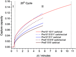
3.1.3. Role of solid-state diffusion-controlled carbonation. Fig. 7 shows the time evolution of the capture capacity during the carbonation stage of the 20th cycle for the different tests whose results are reported in Fig. 6. As is well known, it is observed that carbonation takes place along two well differentiated stages: a fast reaction-controlled stage, where CO2 is chemisorbed on the CaO surface, and a slow solid-state diffusion-controlled stage, where the CO32− and O2− ions counter-diffuse through the carbonate layer built in the fast phase.60 As can be seen in Fig. 7, the fast carbonation stage exhibited by the sorbent tested in our study is much shorter than the diffusion-controlled stage. Thus, most of CO2 is captured in the latter stage. This observation has relevant implications on the predicted capture efficiencies from carbonator models,9 which generally consider the diffusion controlled carbonation phase as negligible according to lab-scale TGA results in which calcination is carried out under low CO2 partial pressure.61 Our results show instead that calcination under high CO2 partial pressure plays a fundamental role in changing the carbonation kinetics across multiple carbonation/calcination cycles. Thus, calcination under high CO2 partial pressure yields a markedly sintered CaO structure with quite a reduced surface area available for fast reaction-controlled carbonation and consequently the capture capacity in this stage is severely hindered. On the contrary, carbonation in the diffusion-controlled stage is relatively enhanced.56,62
image file: c6ra03210a-f7.tif
Fig. 7 Time evolution of the modified steel slag CO2 capture capacity during the 20th cycle, for carbonation/calcination residence times of 5′/5′, 5′/1′ and 10′/1′ with and without a 3′ intermediate recarbonation (rec) stage as indicated. Precalcination (Pre) is carried out at 900 °C (70% CO2/30% air vol/vol) for either 5 or 10 minutes as indicated. Carbonation (carb) at 650 °C (15% CO2/85% air vol/vol) for 5 and 10 minutes, and calcination (cal) at 900 °C (70% CO2/30% air vol/vol) for 1 and 5 minutes as indicated. I indicates the fast reaction-controlled phase and II the slow solid-state diffusion-controlled phase.

With regard to carbonation, it has been proposed that the carbonate grows as islands on the surface of CaO with a critical size that depends on temperature. Surface diffusion is promoted when the temperature is increased in the recarbonation stage, which enhances the growth of these islands. Therefore, new free surface becomes available for carbonation in a fast reaction-controlled stage during the carbonation stage.63,64 As seen in Fig. 7, the capture capacity in the fast stage of the carbonation stage following calcination is significantly improved when a recarbonation stage is introduced before calcination, which indicates that the enhanced carbonation in the recarbonation process promotes the porosity of the regenerated sorbent. Note also in Fig. 7 that the carbonation rate in the solid-state diffusion-controlled phase is increased. Thus, the test carried out by precalcining for 10 minutes, with 5′/1′ carb/cal cycles and introducing the recarbonation stage exhibits the higher capture capacity in the fast carbonation stage as well as the higher diffusive carbonation rate, which leads to a significant enhancement of the total capture capacity at the end of carbonation. Moreover, due to the relevance of diffusion controlled carbonation, the overall capture capacity is further increased by lengthening the carbonation residence time to 10 minutes, as demonstrated for the 10′/1′ test with a precalcination of 10 minutes. Table 1 lists the values of the capture capacity in the fast reaction-controlled stage and in the slow solid-state diffusion-controlled stage measured for the 20th cycle of each test. As can be seen, the superior capture capacity of modified steel slag as compared to limestone after a large number of cycles is mainly due to the enhancement of carbonation in the solid-state diffusion-controlled carbonation phase. The above mentioned results may be taken as relevant inputs for carbonator models in which carbonation during the diffusion-controlled phase is considered to predict the capture efficiency of the CaL process when integrated into a power plant as a function of relevant process parameters such as the residence time of the solids in the carbonator.9

The presence of metallic oxides inert to carbonation in the modified steel slag can improve the thermal stability of the sorbent and promote diffusion, as in the case of MgO grains in dolomite. According to the XRF analysis, the steel slag presents a large amount of SiO2, which has been also reported to act as a thermally stable support for CaO in CaO/SiO2 composites.65 Other authors have proposed that the presence of alumina in small amounts also improves the CO2 capture capacity of solid wastes.42

4. Conclusions

In this study, the multicycle CO2 capture behavior of CaO derived from steel slag modified with acetic acid has been studied at realistic Ca-looping conditions for CO2 capture necessarily involving calcination under high CO2 partial pressure and fast transitions between carbonation and calcination stages. After treatment with acetic acid, almost pure calcium acetate is obtained together with metal oxide impurities that remain inert to carbonation and play a role in stabilizing the CaO capture capacity along multiple carbonation/calcination cycles. The effects of varying the precalcination time as well as the carbonation/calcination residence times and of introducing a recarbonation stage have been investigated.

An important conclusion from this study is that the use of modified steel slag allows operation of the calciner at 900 °C as compared to the 930–950 °C needed for limestone, which would serve to mitigate the energy penalty of the technology. Moreover, if a recarbonation stage is introduced, the modified steel slag shows an increased and stable capture capacity from the first cycle. According to our observations, the marked enhancement of the solid-state diffusion-controlled phase leads to a further noticeable increase in the capture capacity if the carbonation residence time is increased by just a few minutes, which should be considered in the formulation of carbonator models to predict the capture efficiency and energy penalty arising from the integration of the CaL process into power plants.30

The results also demonstrate that under realistic CaL conditions, the calcination residence time for CaO regeneration can be notably shortened when using modified steel slag as a CaO precursor instead of limestone. Thus, the best multicycle capture performance has been obtained by employing a precalcination time of 10 minutes, carbonation for 10 minutes and calcinations of just 1 minute at 900 °C. Under these conditions, modified steel slag exhibits a stable capture capacity in the range of 0.21 to 0.15, which is substantially higher than the residual capture capacity usually reported for limestone-derived CaO.

Acknowledgements

Financial support by the Spanish Government Agency Ministerio de Economia y Competitividad (contracts CTQ2014-52763-C2-2-R and CTQ2014-52763-C2-1-R) and Andalusian Regional Government (Junta de Andalucia-FEDER contracts FQM-5735 and TEP-7858) is acknowledged. The authors thank VPPI-US for the AP current contract. PESJ is supported by a Marie Curie-Junta de Andalucía Talentia grant. The Microscopy, Functional Characterization and X-ray services of the Innovation, Technology and Research Center of the University of Seville (CITIUS) are gratefully acknowledged.

References

  1. O. D. B. Metz, H. D. Coninck, M. Loos and L. Meyer, Special report on carbon dioxide capture and storage, Intergovernmental panel on climate change, New York, NY, USA, technical report, 2005 Search PubMed.
  2. S. Choi, J. H. Drese and C. W. Jones, ChemSusChem, 2009, 2, 796–854 CrossRef CAS PubMed.
  3. Y. C. Lin, C. L. Kong and L. Chen, RSC Adv., 2012, 2, 6417–6419 RSC.
  4. N. MacDowell, N. Florin, A. Buchard, J. Hallett, A. Galindo, G. Jackson, C. S. Adjiman, C. K. Williams, N. Shah and P. Fennell, Energy Environ. Sci., 2010, 3, 1645–1669 CAS.
  5. S. D. Kenarsari, D. L. Yang, G. D. Jiang, S. J. Zhang, J. J. Wang, A. G. Russell, Q. Wei and M. H. Fan, RSC Adv., 2013, 3, 22739–22773 RSC.
  6. J. Blamey, E. J. Anthony, J. Wang and P. S. Fennell, Prog. Energy Combust. Sci., 2010, 36, 260–279 CrossRef CAS.
  7. M. C. Romano, Chem. Eng. Sci., 2012, 69, 257–269 CrossRef CAS.
  8. I. Martínez, G. Grasa, R. Murillo, B. Arias and J. C. Abanades, Chem. Eng. J., 2013, 215–216, 174–181 CrossRef.
  9. C. Ortiz, R. Chacartegui, J. M. Valverde, J. A. Becerra and L. A. Perez-Maqueda, Fuel, 2015, 160, 328–338 CrossRef CAS.
  10. D. P. Hanak, E. J. Anthony and V. Manovic, Energy Environ. Sci., 2015, 8, 2199–2249 CAS.
  11. F. García-Labiano, A. Abad, L. F. de Diego, P. Gayán and J. Adánez, Chem. Eng. Sci., 2002, 57, 2381–2393 CrossRef.
  12. J. M. Valverde, P. E. Sanchez-Jimenez and L. A. Perez-Maqueda, J. Phys. Chem. C, 2015, 119, 1623–1641 CAS.
  13. J. M. Valverde, J. Mater. Chem. A, 2013, 1, 447–468 CAS.
  14. C. Kunze and H. Spliethoff, Appl. Energy, 2012, 94, 109–116 CrossRef CAS.
  15. J. Ylätalo, J. Ritvanen, T. Tynjälä and T. Hyppänen, Fuel, 2014, 115, 329–337 CrossRef.
  16. A. Sánchez-Biezma, J. C. Ballesteros, L. Diaz, E. de Zárraga, F. J. Álvarez, J. López, B. Arias, G. Grasa and J. C. Abanades, Energy Procedia, 2011, 4, 852–859 CrossRef.
  17. M. C. Romano, E. N. Cassotti, P. Chiesa, J. Meyer and J. Mastin, in 10th International Conference on Greenhouse Gas Control Technologies, ed. J. Gale, C. Hendriks and W. Turkenberg, 2011, vol. 4, pp. 1125–1132 Search PubMed.
  18. A. Perejón, L. M. Romeo, Y. Lara, P. Lisbona, A. Martínez and J. M. Valverde, Appl. Energy, 2016, 162, 787–807 CrossRef.
  19. K. Atsonios, P. Grammelis, S. K. Antiohos, N. Nikolopoulos and E. Kakaras, Fuel, 2015, 153, 210–223 CrossRef CAS.
  20. D. C. Ozcan, H. Ahn and S. Brandani, Int. J. Greenhouse Gas Control, 2013, 19, 530–540 CrossRef CAS.
  21. A. Telesca, D. Calabrese, M. Marroccoli, M. Tomasulo, G. L. Valenti, G. Duelli and F. Montagnaro, Fuel, 2014, 118, 202–205 CrossRef CAS.
  22. B. Arias, M. E. Diego, J. C. Abanades, M. Lorenzo, L. Diaz, D. Martínez, J. Alvarez and A. Sánchez-Biezma, Int. J. Greenhouse Gas Control, 2013, 18, 237–245 CrossRef CAS.
  23. J. Ströhle, M. Junk, J. Kremer, A. Galloy and B. Epple, Fuel, 2014, 127, 13–22 CrossRef.
  24. M. H. Chang, C. M. Huang, W. H. Liu, W. C. Chen, J. Y. Cheng, W. Chen, T. W. Wen, S. Ouyang, C. H. Shen and H. W. Hsu, Chem. Eng. Technol., 2013, 36, 1525–1532 CrossRef CAS.
  25. M. Alonso, M. E. Diego, C. Pérez, J. R. Chamberlain and J. C. Abanades, Int. J. Greenhouse Gas Control, 2014, 29, 142–152 CrossRef CAS.
  26. Y. Yang, R. Zhai, L. Duan, M. Kavosh, K. Patchigolla and J. Oakey, Int. J. Greenhouse Gas Control, 2010, 4, 603–612 CrossRef CAS.
  27. P. Lisbona, A. Martínez, Y. Lara and L. M. Romeo, Energy Fuels, 2010, 24, 728–736 CrossRef CAS.
  28. I. Martínez, R. Murillo, G. Grasa and J. Carlos Abanades, AIChE J., 2011, 57, 2599–2607 CrossRef.
  29. Y. Lara, P. Lisbona, A. Martínez and L. M. Romeo, Fuel, 2014, 127, 4–12 CrossRef CAS.
  30. C. Ortiz, R. Chacartegui, J. M. Valverde and J. A. Becerra, Appl. Energy, 2016, 169, 408–420 CrossRef CAS.
  31. J. M. Valverde, P. E. Sanchez-Jimenez and L. A. Perez-Maqueda, Appl. Energy, 2014, 126, 161–171 CrossRef CAS.
  32. L. M. Romeo, Y. Lara, P. Lisbona and A. Martínez, Fuel Process. Technol., 2009, 90, 803–811 CrossRef CAS.
  33. N. Rodríguez, M. Alonso, J. C. Abanades, A. Charitos, C. Hawthorne, G. Scheffknecht, D. Y. Lu and E. J. Anthony, Energy Procedia, 2011, 4, 393–401 CrossRef.
  34. H. Chen, Z. Zhao, X. Huang, K. Patchigolla, A. Cotton and J. Oakey, Energy Fuels, 2012, 26, 5596–5603 CrossRef CAS.
  35. B. Alcantar-Vazquez, P. R. D. Herrera, A. B. Gonzalez, Y. H. Duan and H. Pfeiffer, Ind. Eng. Chem. Res., 2015, 54, 6884–6892 CrossRef CAS.
  36. S. F. Wu, T. H. Beum, J. I. Yang and J. N. Kim, Ind. Eng. Chem. Res., 2007, 46, 7896–7899 CrossRef CAS.
  37. H. Chen, C. Zhao and Q. Ren, J. Environ. Manage., 2012, 93, 235–244 CrossRef CAS PubMed.
  38. N. N. Hlaing, S. Sreekantan, R. Othman, S. Y. Pung, H. Hinode, W. Kurniawan, A. A. Thant, A. R. Mohamed and C. Salime, RSC Adv., 2015, 5, 6051–6060 RSC.
  39. B. Arias, G. S. Grasa, M. Alonso and J. C. Abanades, Energy Environ. Sci., 2012, 5, 7353–7359 CAS.
  40. G. Grasa, I. Martínez, M. E. Diego and J. C. Abanades, Energy Fuels, 2014, 28, 4033–4042 CrossRef CAS.
  41. A. Kaithwas, M. Prasad, A. Kulshreshtha and S. Verma, Chem. Eng. Res. Des., 2012, 90, 1632–1641 CrossRef CAS.
  42. H. K. Park, M. W. Bae, O. S. Yoon and S. G. Kim, Chem. Eng. J., 2012, 195, 158–164 CrossRef.
  43. Y. J. Li, M. Y. Su, X. Xie, S. M. Wu and C. T. Liu, Appl. Energy, 2015, 145, 60–68 CrossRef CAS.
  44. J. Sun, W. Q. Liu, Y. C. Hu, J. Q. Wu, M. K. Li, X. W. Yang, W. Y. Wang and M. H. Xu, Chem. Eng. J., 2016, 285, 293–303 CrossRef CAS.
  45. R. Y. Sun, Y. J. Li, C. T. Liu, X. Xie and C. M. Lu, Chem. Eng. J., 2013, 221, 124–132 CrossRef CAS.
  46. A. H. Ma, Q. M. Jia, H. Y. Su, Y. F. Zhi, N. Tian, J. Wu and S. Y. Shan, Environ. Sci. Pollut. Res., 2016, 23, 2530–2536 CrossRef CAS PubMed.
  47. T. Ariyama and M. Sato, ISIJ Int., 2006, 46, 1736–1744 CrossRef CAS.
  48. D. Bonenfant, L. Kharoune, S. Sauve, R. Hausler, P. Niquette, M. Mimeault and M. Kharoune, Int. J. Greenhouse Gas Control, 2009, 3, 20–28 CrossRef CAS.
  49. J. Yu and K. B. Wang, Energy Fuels, 2011, 25, 5483–5492 CrossRef CAS.
  50. I. Ortega-Fernández, N. Calvet, A. Gil, J. Rodríguez-Aseguinolaza, A. Faik and B. D'Aguanno, Energy, 2015, 89, 601–609 CrossRef.
  51. S. C. Tian, J. G. Jiang, F. Yan, K. M. Li and X. J. Chen, Environ. Sci. Technol., 2015, 49, 7464–7472 CrossRef CAS PubMed.
  52. S. C. Tian, J. G. Jiang, K. M. Li, F. Yan and X. J. Chen, RSC Adv., 2014, 4, 6858–6862 RSC.
  53. J. Panzer, J. Chem. Eng. Data, 1962, 7, 140–142 CrossRef CAS.
  54. D. D. Dionysiou, M. Tsianou and G. D. Botsaris, Cryst. Res. Technol., 2000, 35, 1035–1049 CrossRef CAS.
  55. M. Broda, A. M. Kierzkowska and C. R. Muller, Adv. Funct. Mater., 2014, 24, 5753–5761 CrossRef CAS.
  56. J. M. Valverde, P. E. Sanchez-Jimenez and L. A. Perez-Maqueda, Appl. Energy, 2015, 138, 202–215 CrossRef CAS.
  57. S. Niu, K. Han, C. Lu and R. Sun, Appl. Energy, 2010, 87, 2237–2242 CrossRef CAS.
  58. M. D. Judd, B. A. Plunkett and M. I. Pope, J. Therm. Anal., 1974, 6, 555–563 CrossRef CAS.
  59. G. S. Grasa and J. C. Abanades, Ind. Eng. Chem. Res., 2006, 45, 8846–8851 CrossRef CAS.
  60. S. K. Bhatia and D. D. Perlmutter, AIChE J., 1983, 29, 79–86 CrossRef CAS.
  61. M. Alonso, N. Rodríguez, G. Grasa and J. C. Abanades, Chem. Eng. Sci., 2009, 64, 883–891 CrossRef CAS.
  62. E. P. Hyatt, I. B. Cutler and M. E. Wadsworth, J. Am. Ceram. Soc., 1958, 41, 70–74 CrossRef CAS.
  63. Z. Li, H. Sun and N. Cai, Energy Fuels, 2012, 26, 4607–4616 CrossRef CAS.
  64. Z.-s. Li, F. Fang, X.-y. Tang and N.-s. Cai, Energy Fuels, 2012, 26, 2473–2482 CrossRef CAS.
  65. P. E. Sanchez-Jimenez, L. A. Perez-Maqueda and J. M. Valverde, Appl. Energy, 2014, 118, 92–99 CrossRef CAS.

This journal is © The Royal Society of Chemistry 2016
Click here to see how this site uses Cookies. View our privacy policy here.