Hybrid LiV3O8/carbon encapsulated Li1.2Mn0.54Co0.13Ni0.13O2 with improved electrochemical properties for lithium ion batteries

Kailing Suna, Can Penga, Zhaohui Li*a, Qichang Xiaoa, Gangtie Leia, Qizhen Xiaoa, Yanhuai Dingb and Zhongliang Huc
aKey Laboratory of Environmentally Friendly Chemistry and Applications of Ministry of Education, College of Chemistry, Xiangtan University, Hunan 411105, PR China. E-mail: lzh69@xtu.edu.cn; Fax: +86 731 58292251; Tel: +86 731 58292206
bCollege of Civil Engineering & Mechanics, Institute of Rheology Mechanics, Xiangtan University, Hunan 411105, PR China
cCollege of Metallurgic Engineering, Hunan University of Technology, Hunan 412007, PR China

Received 29th January 2016 , Accepted 4th March 2016

First published on 8th March 2016


Abstract

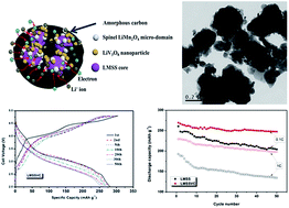
A low coulombic efficiency in the first cycle and poor rate capability limit the practical application of a lithium rich manganese-based solid solution (LMSS) in lithium ion batteries. To resolve these problems, a core–shell type of Li1.2Mn0.54Co0.13Ni0.13O2@LiV3O8/C (LMSSVC) composite material was prepared using a sol–gel process, in which NH4VO3-derived V2O5 chemically leached lithium from the LMSS and formed the LiV3O8 during high temperature annealing. The effect of the hybrid LiV3O8/C layer on the electrochemical properties of the LMSS is investigated using cyclic voltammetry, electrochemical impedance spectroscopy and galvanostatic charge–discharge measurements. The as-prepared LiV3O8 nanoparticles are embedded within the carbon matrix uniformly, which becomes an outer shell to encapsulate the LMSS nanoparticles. Because of the Li-host nature of LiV3O8 and the electronic conductivity of carbon, the LMSSVC can deliver a capacity of 269 mA h g−1 at a 0.1C rate in the first cycle over the voltage range of 2.0–4.8 V together with a coulombic efficiency of 94%, and retain 94% of the initial capacity after 50 cycles. It can deliver capacities of 258, 245, 229, 207 and 176 mA h g−1 at the rates of 0.2C, 0.5C, 1C, 2C and 5C, respectively. The results indicate that surface coating of the hybrid LiV3O8/C layer can improve not only the initial coulombic efficiency but also the rate capability of the LMSS material.


1. Introduction

Because of their high energy density which is close to 900 W h kg−1, lithium (Li) rich manganese-based solid solution (LMSS) materials are considered to be promising cathode materials for the next generation Li ion batteries.1–5 There are a variety of LMSS materials, and amongst these, the xLi2MnO3·(1 − x)Li(Mn1/3Co1/3Ni1/3)O2 has a specific capacity close to 300 mA h g−1 which is obtained by varying the components of Li2MnO3 and Li(Mn1/3Co1/3Ni1/3)O2, to give for example, 0.5Li2MnO3·0.5Li(Mn1/3Co1/3Ni1/3)O2 (also designated as Li1.2Mn0.54Co0.13Ni0.13O2) which has been studied extensively in the past decade.4–9 The Li2MnO3 component is thought to be electrochemically inactive in the first charge process because it is too difficult to oxidize the Mn4+ to a higher valence in the current organic carbonate-based electrolyte. However, it could remove the lithium oxide (Li2O) component accompanying the oxygen gas released when charged to a potential of more than 4.5 V (usually to 4.8 V versus Li+/Li) in the first cycle.10–19 As a result, the LMSS materials suffer from an irreversible capacity, leading to a low coulombic efficiency in the first cycle. In addition, the LMSS has a low electronic conductivity because of the insulated Li2MnO3 component, resulting in poor rate capability. The aforementioned problems seriously hamper the widespread application of the LMSS in high-power lithium ion batteries.

To resolve these problems, researchers have made a number of attempts, among which surface coating is an effective methodology, to improve both initial coulombic efficiency and rate capability of the LMSS materials. The surface-coating compounds include three kinds of materials: (1) electrochemically inactive materials such as Al2O3,20,21 aluminium phosphate (AlPO4),22,23 AlF3,24,25 CaF2,26 LaPO4 (ref. 27) and Sm2O3,28 (2) electrochemically active materials such as manganese oxide (MnO2),29 vanadium(V) oxide (V2O5),30 α-MoO3,31 LiNi0.5Mn1.5O4,32 FePO4,33 LiMnPO4 (ref. 34) and Li4Ti5O12,35 and (3) conductive materials such as polymers36 and carbon (C).37 Simple mixing of V2O5 or lithium trivanadate (LiV3O8) with the LMSS could enhance its initial coulombic efficiency, but its cycling performance and rate capability were unaltered.30 The reason for this, is that simple mixing could not shield the LMSS from contacting the electrolyte, therefore, the V2O5-coated Li1.2Mn0.54Co0.13Ni0.12O2 presented an improved cyclability because the V2O5-coating layer can physically separate the LMSS from the electrolyte.38 Unfortunately, this coated sample revealed an inferior rate capability because of the low electronic/ionic conductivity of V2O5. It was, therefore, necessary to coat the LMSS materials with both electron and ion conductive materials to improve their initial coulombic efficiency, rate capability and cyclability. Accordingly, a hybrid coating of carbon and a Li-conductive material is a good choice, which has been adopted to improve the electrochemical properties of the cathode materials.39–41

In this research, a hybrid LiV3O8/carbon layer was coated on the surface of the LMSS particles. In the surface coating process, ammonium metavanadate (NH4VO3) is decomposed first to yield V2O5 nanoparticles. Then the V2O5 nanoparticles formed leach lithium from the LMSS to produce a spinel component and LiV3O8 during annealing at a high temperature. The as-prepared LMSS@LiV3O8/C was characterized using scanning electron microscopy (SEM), transmission electron microscopy (TEM), X-ray diffraction (XRD) technologies, and X-ray photoelectron spectroscopy (XPS). Its electrochemical properties were evaluated using cyclic voltammetry (CV), electrochemical impedance spectroscopy (EIS) and galvanostatic charge–discharge measurements. The results suggested that the electrochemical properties of the LMSS material were improved greatly by surface coating of the hybrid LiV3O8/C layer.

2. Experimental

2.1 Synthesis of the core–shell LMSSVC

The Li1.2Mn0.54Co0.13Ni0.13O2 nanoparticles were prepared using a sol–gel method reported in previous research.25,28 The Li/Mn/Co/Ni atomic ratio was determined to be 1.216[thin space (1/6-em)]:[thin space (1/6-em)]0.534[thin space (1/6-em)]:[thin space (1/6-em)]0.128[thin space (1/6-em)]:[thin space (1/6-em)]0.131 using inductively coupled plasma atomic emission spectrometry (ICP-AES, Profile spectrometer, Leeman Laboratories), which is close to the theoretical metal atomic ratio of raw Li1.2Mn0.54Co0.13Ni0.13O2. Portions of NH4VO3 (2.0 g) and sucrose (4.5 g) were added to a 50 mL suspension that contained 10 g of the LMSS nanoparticles and the mixture was stirred at 25 °C for 1 h. Then, the water was evaporated at 80 °C under slow mechanical agitation to obtain a dry powder. The dry powder was heated from room temperature to 250 °C and then held at this temperature for 3 h, and then sintered at 450 °C for 2 h in static air to yield the final coated sample (designated as the LMSSVC). Such a thermal treatment procedure was determined from the thermogravimetric and derivative thermogravimetric curves of the LMSSVC precursor (see Fig. S1, ESI).

2.2 Characterizations

Thermogravimetric analysis (TGA) was performed (Q50 TGA instrument, TA Instruments) in static air at 10 °C min−1 from room temperature to 600 °C. The chemical compositions of the samples were determined using ICP-AES. The morphology of the sample was observed using a SEM (S-4800, Hitachi) and TEM (JEM-2010, JEOL). Powder XRD patterns (D8 Advance diffractometer, Bruker) were recorded using a monochromatic Cu Kα X-ray (λ = 0.154 nm) source at a scan rate of 2° min−1. XPS (ESCALAB 250Xi, Thermo Scientific) measurements were used to determine the chemical states of the vanadium and manganese elements.

The porous property of the sample was determined using nitrogen adsorption at 77 K (TriStar II 3020, Micromeritics). The test sample was evacuated at 120 °C under 0.1 Pa pressure prior to adsorption. The tap density of the sample was determined using a small graduated measuring cylinder and which was tapped until the volume remained unchanged.

2.3 Electrochemical measurements

The LMSS or LMSSVC powders were mixed with polyvinylidene fluoride, and acetylene black at a mass ratio of 80[thin space (1/6-em)]:[thin space (1/6-em)]10[thin space (1/6-em)]:[thin space (1/6-em)]10 in N-methyl pyrrolidinone to form a slurry. The obtained slurry was then coated on an aluminium (Al)-foil, dried at 120 °C overnight, and punched into discs of 12 mm diameter, which were used as the cathodes. The electrochemically active materials such as LMSS and LMSSVC were weighed to about 3.80 mg and then loaded on to one piece of the 12 mm disc, which gave a mass loading of the electroactive materials equal to 3.36 mg cm−2 on the electrode. The cathodes were assembled with the Li anode, a porous polypropylene separator (Celgard 2300), and the electrolyte 1 M lithium hexafluorophosphate (LiPF6) in 1[thin space (1/6-em)]:[thin space (1/6-em)]1 ethylene carbonate/dimethyl carbonate into coin type cells (2016#).

Galvanostatic charge–discharge measurements were performed at various rates (the 1C rate was equal to 250 mA g−1) within a voltage window of 2.0–4.8 V using a battery tester (Neware). EIS and CV measurements were carried out using an electrochemical workstation (604E, CH Instruments).

The electrical conductivity of the LMSSVC or LMSS was measured using a four point probe testing system (ST2722, Suzhou Jingge Electronic Co., China). The samples were prepared by pressing the dried powder under a pressure of 20 MPa for 3 min to form a wafer with a 12 mm diameter.

3. Results and discussion

3.1 Crystal structure

Fig. 1 shows the XRD patterns of the LMSS and LMSSVC samples. It can be seen that the characteristic diffraction peaks in the pattern of the LMSS sample can be indexed to a hexagonal α-NaFeO2 structure with a space group of R[3 with combining macron]m, which is normally taken as the signature of the LiMO2 phase.7–9,12,15 In addition, there are two sets of well separated diffraction peaks located at (008)/(110), and (006)/(012), indicating that the crystallites have a good layered structure.7 The weak diffraction peaks at 2θ = 20.72° and 21.69° correspond to the (020) and (110) crystal planes, respectively, belonging to the LiMn6 super-ordering in the Li2MnO3 monoclinic phase with C2/m symmetry.6 In addition, the intensity ratio of the (003) to the (104) crystal plane (I(003)/(104)) is 1.31 for LMSS and 1.28 for the LMSSVC, which indicates a low degree of cation mixing of the Li+ and Ni2+ ions. Because of the similar ion radius of Ni2+ (0.69 Å) to Li+ (0.76 Å), Ni2+ (3b site, transition metal layer) could be exchanged with Li+ (3a site, lithium layer) during sintering thus causing cation mixing.
image file: c6ra02688e-f1.tif
Fig. 1 XRD patterns of the LMSS and LMSSVC samples compared with JCPDS standard cards for LiV3O8, Li0.3V2O5 and V2O5. The right and bottom XRD patterns are the enlarged ones over the 2θ range of 35–40° and 20–25°, respectively.

Comparing the LMSS with the LMSSVC revealed a similar XRD pattern except for some new diffraction peaks which had appeared (marked as * in the XRD pattern). These peaks (at 2θ = 13.89°, 15.57°, 23.38°, 27.54°, 28.01°, 30.98°, 41.03° and 42.53°) are different from those of the V2O5 (JCPDS no. 41-1426). They can be ascribed to the (100), (002), (003), (−202), (−111), (103), (−301/−205) and (203) crystal planes of the LiV3O8 (JCPDS no. 35-0437), respectively. Two other peaks at 2θ = 50.87° and 60.35° might be attributed to the (406) and (017) crystal planes of the Li0.3V2O5 (JCPDS no. 73-1670), respectively. The results suggest that the LiV3O8 forms in the hybrid coating layer when the precursor is annealed at a high temperature. Whereas the Li0.3V2O5 might come from the reduction of a small amount of LiV3O8 because of the intercalation of Li+ ions and/or carbothermal reduction.

The diffraction peaks around 2θ = 36.5° next to the (101) crystal plane for the LMSS are different from those for the LMSSVC (Fig. 1 right), suggesting that a new crystal phase (spinel) has formed in the surface coated sample because of the chemical leaching effect of V2O5.30,42 Furthermore, the LMSSVC exhibited the intensities of the diffraction peaks relative to the LiMn6 super-ordering which were lower than those of the LMSS (Fig. 1 bottom left), implying that some Li2MnO3 crystallites had changed their crystal structure.

XPS measurements were conducted to determine the valence states of the elements in the samples. Fig. 2 shows the survey XPS spectra (a) and the fitted spectra of Mn 2p3/2 (b) and V 2p3/2 (c) of the samples. The XPS signals for Li 1s, Mn 2p, Co 2p and Ni 2p are found in the pristine sample whereas an additional signal of V 2p is found in the LiV3O8/C decorated sample.43–45 As was reported, the binding energies of Mn 2p3/2 at 641.07 and 642.41 eV were assigned to Mn3+ and Mn4+, respectively.46,47 It was found that the intensity of the Mn 2p3/2 signal at 641.45 eV for the LMSSVC is stronger than that for the LMSS (Fig. 2b). This suggests the amount of Mn3+ in LMSSVC is higher than that in LMSS, which possibly results from the formation of the spinel phase after surface modification. The binding energies assigned to the V 2p3/2 signal at 517.6 and 516.4 eV can be ascribed to the oxidation states of V5+ and V4+, respectively,48,49 as shown in Fig. 2c. The V5+ oxidation state originated from the LiV3O8 oxides formed, whereas the V4+ oxidation state came from the reduction of a small amount of V5+ ions, which was caused by the intercalation of Li+ ions and/or a carbothermal reduction.


image file: c6ra02688e-f2.tif
Fig. 2 XPS spectra of the LMSS and LMSSVC: (a) survey, (b) Mn 2p3/2 with the fitted spectra, and (c) V 2p3/2 with fitted spectra.

3.2 Morphology study

Fig. 3 shows the SEM images of the LMSS (a) and LMSSVC (b) samples. It was found that the pristine LMSS sample had a large number of nanoparticles with a diameter of 30 nm and a small amount of nanoparticles with diameters between 100 and 200 nm. These nanoparticles with a smooth surface aggregate slightly (Fig. 3a). After surface coating with the LiV3O8/C hybrid layer, the pristine LMSS nanoparticles grew to give sub-micrometer particles with a size range of 200–300 nm, accompanied with the disappearance of many 30 nm sized nanoparticles. This is because multiple LMSS nanoparticles were encapsulated by the LiV3O8/C hybrid layer and merged into one single particle (Fig. 3b). The LiV3O8 nanoparticles were embedded uniformly within the carbon matrix. As a result, a few of the nanoparticles seemed to be packed in a nearly spherical shell to form a pomegranate like structure.
image file: c6ra02688e-f3.tif
Fig. 3 SEM images of LMSS (a) and LMSSVC (b).

TEM and high-resolution TEM (HRTEM) images of the LMSSVC are shown in Fig. 4. It was observed that the LMSSVC particles were constructed with nanoparticles with a size of 30 nm and their size was about 150 nm (Fig. 4a). From the energy dispersive spectrometry (EDS) analysis of the selected area (Fig. 4d), it can be seen that the Li, V and C elements are present in the coating layer. This confirms the formation of the LiV3O8 component in the coating layer. From Fig. 4b, the thickness of the LiV3O8/C hybrid layer is seen to be about 35 nm, in which the LiV3O8 nanoparticles with a size of 5–10 nm are dispersed uniformly. Selected area energy diffraction (SAED) patterns indicate that the carbon is amorphous (Fig. 4b1) and that the LiV3O8 is polycrystalline (Fig. 4b2). Fig. 4c shows the HRTEM image of the interface between the LMSS and the coating layer. A micro-domain with a spinel structure is clearly presented because its SAED pattern (Fig. 4c1) is different from that of the LMSS (Fig. 4c2). As the V2O5 can chemically extract Li+ ions from the LMSS core, the Li2MnO3 component is activated like those activated by acid treatments as previously reported.50


image file: c6ra02688e-f4.tif
Fig. 4 TEM images of the LMSSVC (a) and HRTEM images of the selected area (b) and the interface between the pristine LMSS and LiV3O8/C hybrid layer (c). (d) The EDS analysis of the selected area in Fig. 4b. SAED patterns of the selected area are presented in (b1), (b2), (c1), and (c2).

3.3 Porous structure analysis

Fig. 5 displays the nitrogen adsorption isotherms of the LMSSVC sample. It was found that the adsorption isotherms appear as a type-IV curve with a type-H3 hysteresis loop, indicating the existence of mesopores. The Brunauer–Emmett–Teller surface area and the Barrett–Joyner–Halenda pore volume were 25.76 m2 g−1 and 0.154 cm3 g−1, respectively. The maximum pore size distribution of mesopores is 10 nm, whereas that of the micropores was 2 nm (Fig. 5 inset). Also, some macropores with a size of 30 nm were found. Such a porous structure would allow the electrolyte to penetrate the hybrid coating layer and move into the interior of bulk particles, providing the electrode materials with a high chargeability. Furthermore, this porous structure is very beneficial to long-life cycling of batteries because it can accommodate volume changes of the electrode materials during charge and discharge. However, its tap density is about 1.42 ± 0.05 g cm−3 because of the porous structure.
image file: c6ra02688e-f5.tif
Fig. 5 Nitrogen adsorption isotherms of the LMSSVC sample and its pore size distribution (inset).

3.4 Electrochemical properties

3.4.1 Cycling performance. Galvanostatic charge–discharge curves of the LMSS (a) and LMSSVC (b) samples at a 0.1C rate in the different cycles are shown in Fig. 6. It was found that, in the first charging profile, the 0.5Li(Mn1/3Co1/3Ni1/3)O2 component is delithiated less than 4.4 V (versus Li/Li+), whereas Li2O is extracted from the 0.5Li2MnO3 component over the potential range of 4.4–4.8 V.3,51 During these two potential ranges, the LMSS was charged with 125 and 229 mA h g−1 (Fig. 6a). As for the LMSSVC, the charged capacity of 26 mA h g−1 below 3.7 V was attributed to the LiV3O8 component whereas that of 116 mA h g−1 originates from the 0.5Li(Mn1/3Co1/3Ni1/3)O2 (Fig. 6b). The 0.5Li2MnO3 component can be only charged with 144 mA h g−1, which was much lower than that of the LMSS, implying that a certain amount of Li2MnO3 has been delithiated before charging. In particular, during the surface coating process, a part of Li2MnO3 has been activated by the V2O5 component from the decomposition of NH4VO3, which leads to the formation of LiV3O8. It is worth noting that the LMSSVC revealed multiple potential plateaus at 2.9, 3.2, and 3.4 V (see Fig. S3, ESI). These plateaus were relative to the LiV3O8 component, and are still found in the subsequent charge curves.
image file: c6ra02688e-f6.tif
Fig. 6 Galvanostatic charge–discharge curves of the LMSS (a) and LMSSVC (b) samples, their coulombic efficiency in the different cycles (c), and cycling performance (d) at the 0.1C rate (25 mA g−1) over the voltage range of 2.0–4.8 V at room temperature.

For the discharge profiles, the LMSS had a higher potential plateau than the LMSSVC but the former exhibited more dramatic voltage fade. Because the lithiation potentials of LiV3O8 were usually lower than those of Ni1/3Co1/3Mn1/3O2 that originated from the fully charged LMSS, the LMSSVC exhibits a lower potential plateau. However, the LMSSVC can deliver a capacity of 269 mA h g−1 at a 0.1C rate in the first cycle, which is higher than that of the LMSS (259 mA h g−1) by 10 mA h g−1. The extra capacity from the LiV3O8 can compensate a little capacity for the LMSS cores, so the LMSSVC has an initial coulombic efficiency of up to 94%, which is higher than that of the LMSS (73%) (Fig. 6c).

Fig. 6d shows the cycling performance of the LMSS and LMSSVC when operated at 0.1C and 1C rates within the voltage range of 2.0–4.8 V at room temperature. It was found that, after 50 cycles, the LMSS and LMSSVC deliver the capacities of 204 and 247 mA h g−1, respectively, at the 0.1C rate, which corresponded to 79% and 92% of their own initial ones. For the 1C rate, the capacity retentions were 70% and 86% for the LMSS and LMSSVC, respectively, after 50 cycles. The LMSSVC exhibited better cycling performance than the LMSS because the carbon coating layer can shield not only the LMSS cores but also the LiV3O8 nanoparticles from directly contacting the electrolyte.52

3.4.2 Rate capability. The rate capabilities of the LMSS and LMSSVC samples are presented in Fig. 7. It was found that the discharge capacities at the 0.1C, 0.2C, 0.5C, 1C, 2C and 5C rates were 269, 258, 245, 229, 207 and 176 mA h g−1 for the LMSSVC, respectively. The corresponding capacities were 258, 237, 208, 192, 166 and 108 mA h g−1 for the LMSS. Obviously, the LMSSVC possessed a rate capability superior to the LMSS, which was a benefit from the carbon-coating layer as well as the spinel LiMn2O4 micro-domains surrounding the LMSS core as illustrated in Fig. 8. Through the amorphous carbon layer, electrons can transfer fast to the electroactive materials, including the LiV3O8 nanoparticles, the spinel LiMn2O4 micro-domains and the LMSS cores. As a result, the electronic conductivity (5.7 × 10⁻² S cm−1) of the LMSSVC is higher than that of the LMSS (6.2 × 10⁻⁴ S cm−1) by about two orders of magnitude. The Li+ ions can also diffuse easily from the core through the spinel micro-domains because of the effect of an “alkali ion pump”53 and three-dimensional (3D) ion-diffusion channels.54 Furthermore, the electrolyte can penetrate into the bulk particles through the hierarchical pores within the carbon matrix. The 3D ion-conductive network formed, facilitates diffusion of Li+ ions into the bulk particles.54,55 As a result, the rate capability of the LMSSVC is superior to those of the encapsulated carbon nanofiber,56 the carbon coated,57 the surface double phase network modified,58 the hybrid lithium phosphate (Li3PO4)/C coated,59 and the reduced graphene oxide (RGO)/AlPO4 hybrid coated,60 and is comparable to that of hierarchical Li1.2Ni0.13Mn0.54Co0.13O2 spheres.61 For comparison, Table 1 shows the initial coulombic efficiency, rate capability and cyclability of the previously mentioned LMSS materials.
image file: c6ra02688e-f7.tif
Fig. 7 Rate capabilities of the LMSS and LMSSVC samples within the voltage range of 2.0–4.8 V at room temperature.

image file: c6ra02688e-f8.tif
Fig. 8 Schematic illustration of the electrochemical reaction mechanism for the LMSSVC material.
Table 1 Initial coulombic efficiency, rate capability and cyclability of the various LMSS materials
Sample Initial coulombic efficiency (at x rate) Rate capability, discharge capacity (at x rate) mA h g−1 Cyclability, capacity retention (at x rate after n cycles) Ref.
Li1.2Ni0.13Co0.13Mn0.54O2-encapsulated carbon nanofiber network 83.5% (0.2C) 219.5 (1C) 80.5% (at 1C after 100 cycles) 56
125 (5C)
Carbon-coated Li1.2Ni0.13Co0.13Mn0.54O2 79.5% (0.1C) 203.9 (1C) 70.6% (at 0.5C after 80 cycles) 57
154.7 (5C)
Double phase modified Li1.2Ni0.13Co0.13Mn0.54O2 ∼60% (0.05C) 210 (1C) 108% (at 0.5C after 100 cycles) 58
154 (5C)
Hybrid Li3PO4/C coated Li1.2Ni0.13Co0.13Mn0.54O2 87.0% (0.1C) 180 (1C) 87.3% (at 0.5C after 200 cycles) 59
124.4 (5C)
RGO/AlPO4 coated Li[Li0.190Mn0.540Co0.143Ni0.127]O2 81.4% (0.1C) 170 (1C) 94.2% (at 0.1C after 100 cycles) 60
110 (5C)
Hierarchical spherical Li1.2Ni0.13Mn0.54Co0.13O2 ∼74.2% (0.1C) 228.6 (1C) 90% (at 1C after 100 cycles) 61
180.6 (5C)
Li1.2Mn0.54Co0.13Ni0.13O2@LiV3O8/C core–shell composite material 94% (0.1C) 229 (1C) 92% (at 0.1C after 50 cycles) This work
176 (5C)


3.4.3 Cyclic voltammograms. Fig. 9 displays the cyclic voltammograms of the LMSS (a) and LMSSVC (b) for the first three cycles at room temperature. It can be seen that for the LMSS, the oxidation (delithiation) peak potentials located at 4.1 V and 4.7 V can be ascribed to the changes of Ni2+/Co2+ to Ni4+/Co4+ and O2− to O22− in the first charging process, respectively (Fig. 9a). The former peak potential shifted to 3.9 V whereas the latter one disappeared in subsequent cycles, indicating that part of Li+ ions that were extracted as the component of Li2O were irreversible. In the discharging process, the LMSS underwent a reduction (lithiation) reaction, in which Co4+ is reduced to Co2+ at 4.2 V, Ni4+ to Ni2+ at 3.7 V and Mn4+ to Mn3+ at 3.3 V, respectively. Mn4+ ions might originate from the MnO2 component formed in the reaction of Li2MnO3 → MnO2 + Li2O during the initial charging to 4.8 V.
image file: c6ra02688e-f9.tif
Fig. 9 Cyclic voltammograms of the LMSS (a) and LMSSVC (b) within the potential range of 2.0–4.8 V (versus Li/Li+) for the first three cycles at the scanning rate of 0.1 mV s−1.

The LMSSVC displayed an integral area surrounded by the peak potential at 4.7 V which was less than that of the LMSS (Fig. 9b). During the charge (delithiation) process, the Li+ ions extracted from the LMSS core could insert into the electroactive LiV3O8, which would consume some Li+ ions. As a result, the LMSSVC has a shorter potential plateau at 4.5 V (versus Li+/Li) than that of the LMSS (Fig. 5a). However, the Li1+xV3O8 formed can release Li+ ions to compensate for the irreversible capacity loss of the LMSS core. It is because of this that the LMSSVC exhibits different CVs from the LMSS. Also, the spinel micro-domains that formed by chemical leaching revealed a reduction reaction (lithiation) at the potential of 2.8 V. Furthermore, two additional peak potentials appear at 2.7 V and 2.5 V in the initial discharging process and there were another two additional ones located at 2.7 V and 3.0 V in the subsequent charging process. These redox peak potentials were relative to the LiV3O8 compound.

3.4.4 Electrochemical impedance spectra. Fig. 10 shows the EIS of the LMSS and LMSSVC electrodes before and after 50 cycles. The depicted Nyquist plots appear as depressed semicircles in the high frequency range and straight lines inclined at a constant angle to the real axis in the low frequency range. The depressed semicircle suggests a non-ideal capacitance double layer response at the electrode/electrolyte interface so it could be represented by a parallel combination of a resister and a constant phase element in the equivalent circuit (Fig. 10 inset). The diameter of the deformed semicircle on the Zre axis is relative to charge transfer resistance (Rct). It can be seen that the initial Rct value of the LMSSVC is lower than that of the LMSS. This is because of the hybrid outer shell which might decrease the contacting resistance between the primary LMSS nanoparticles and supply continuous channels for electron and ion transportation (Fig. 8). After 50 cycles, the Rct value increases to 141 Ω for the LMSSVC whereas it reaches 376 Ω for the LMSS. The reason is that the LiV3O8/C hybrid layer shields the LMSS cores from the attack of hydrofluoric acid, which originated from the hydrolysis of LiPF6 in the electrolyte.62 This type of “physical buffer” effect that has been acknowledged widely for the core–shell electrode materials could reduce the dissolution of electro-active materials into electrolyte.63–66 As a consequence, the LMSSVC electrode possesses cyclability superior to that of the LMSS.
image file: c6ra02688e-f10.tif
Fig. 10 Nyquist curves of the LMSS and LMSSVC before and after cycling at a 0.1C rate for 50 times and charging to 4.5 V.

4. Conclusions

A hybrid LiV3O8/C layer was successfully coated on the surface of the LMSS particles that were prepared by a sol–gel method and formed a core–shell type of composite material. The core particles were about 150 nm in size and formed from 30 nm nanoparticles encapsulated by the LiV3O8/C outer shell and with a 35 nm thickness. The LiV3O8 nanoparticles (5–10 nm in diameter) embedded within the carbon matrix uniformly. They were produced by the reaction of the V2O5 generated from NH4VO3 with the lithium chemically leached from the core, which caused spinel micro-domains which were able to form on the surface of LMSS. The core–shell Li1.2Mn0.54Co0.13Ni0.13O2@LiV3O8/C composite material obtained had a coulombic efficiency of 94% in the first cycle. It could deliver the capacities of 269, 258, 245, 229, 207 and 176 mA h g−1 at the rates of 0.1C, 0.2C, 0.5C, 1C, 2C and 5C within the voltage range of 2.0–4.8 V, respectively. The capacity retention was 94% of the initial one at a 0.1C rate after 50 cycles. The results indicate that the surface-coating of the hybrid LiV3O8/C layer is a feasible technique to improve the initial coulombic efficiency, rate capability and cyclability of the LMSS material. The core–shell LMSSVC composite produced could develop into a promising cathode material for high-density lithium ion batteries.

Acknowledgements

The authors greatly appreciate the financial support from the Program for Key R&D plan of Hunan Province (2015JC3091), the National Natural Science Foundation of China (No. 21174119, 21376069, 21576075), the Program for Innovative Research Cultivation Team in University of Ministry of Education of China (1337304), and the Hunan Natural Science Foundation (2015JJ3115).

References

  1. S. H. Kang and K. Amine, J. Power Sources, 2003, 124, 533–537 CrossRef CAS.
  2. Y. Wu and A. Manthiram, J. Power Sources, 2008, 183, 749–754 CrossRef CAS.
  3. M. M. Thackeray, S. H. Kang, C. S. Johnson, J. T. Vaughey, R. Benedek and S. A. Hackney, J. Mater. Chem., 2007, 17, 3112–3125 RSC.
  4. H. Yu and H. Zhou, J. Phys. Chem. Lett., 2013, 4, 1268–1280 CrossRef CAS PubMed.
  5. S. H. Kang and M. M. Thackeray, J. Electrochem. Soc., 2008, 155, 269–275 CrossRef.
  6. C. S. Johnson, N. Li, C. Lefief, J. T. Vaughey and M. M. Thackeray, Chem. Mater., 2008, 20, 6095–6106 CrossRef CAS.
  7. N. Yabuuchi, K. Yoshii, S. T. Myung, I. Nakai and S. Komaba, J. Am. Chem. Soc., 2011, 133, 4404–4419 CrossRef CAS PubMed.
  8. Y. Huang, X. Hou, S. Ma, X. Zou, Y. Wu, S. Hu, Z. Shao and X. Liu, RSC Adv., 2015, 5, 25258–25265 RSC.
  9. S. J. Shi, J. P. Tu, Y. Y. Tang, Y. Q. Zhang, X. L. Wang and C. D. Gu, J. Power Sources, 2013, 240, 140–148 CrossRef CAS.
  10. J. Hong, H. D. Lim, M. Lee, S. W. Kim, H. Kim, S. T. Oh, G. C. Chung and K. Kang, Chem. Mater., 2012, 24, 2692–2697 CrossRef CAS.
  11. J. Li, C. Zhan, J. Lu, Y. Yuan, R. Shahbazian-Yassar, X. Qiu and K. Amine, ACS Appl. Mater. Interfaces, 2015, 7, 16040–16045 CAS.
  12. C. Genevois, H. Koga, L. Croguennec, M. Ménétrier, C. Delmas and F. Weill, J. Phys. Chem. C, 2015, 119, 75–83 CAS.
  13. Z. Q. Deng and A. Manthiram, J. Phys. Chem. C, 2011, 115, 7097–7103 CAS.
  14. X. Xiang, J. C. Knight and W. Li, J. Phys. Chem. C, 2014, 118, 23553–23558 CAS.
  15. H. Koga, L. Croguennec, M. Ménétrier, P. Mannessiez, F. Weill, C. Delmas and S. Belin, J. Phys. Chem. C, 2014, 118, 5700–5709 CAS.
  16. R. Shunmugasundaram, R. S. Arumugam and J. R. Dahn, Chem. Mater., 2015, 27, 757–767 CrossRef CAS.
  17. M. G. Verde, H. Liu, K. J. Carroll, L. Baggetto, G. M. Veith and Y. S. Meng, ACS Appl. Mater. Interfaces, 2014, 6, 18868–18877 CAS.
  18. Y. Jiang, Z. Yang, W. Luo, X. L. Hu, W. X. Zhang and Y. H. Huang, J. Mater. Chem., 2012, 22, 14964–14969 RSC.
  19. Y. Jiang, Z. Yang, W. Luo, X. L. Hu and Y. H. Huang, Phys. Chem. Chem. Phys., 2013, 15, 2954–2960 RSC.
  20. J. T. Lee, F. M. Wang, C. S. Cheng, C. C. Li and C. H. Lin, Electrochim. Acta, 2010, 55, 4002–4006 CrossRef CAS.
  21. Y. Huang, J. Chen, F. Cheng, W. Wan, W. Liu, H. Zhou and X. Zhang, J. Power Sources, 2010, 195, 8267–8274 CrossRef CAS.
  22. X. Ma, C. Wang, X. Han and J. Sun, J. Alloys Compd., 2008, 453, 352–355 CrossRef CAS.
  23. Y. Wu, A. V. Murugan and A. Manthiram, J. Electrochem. Soc., 2008, 155, 635–641 CrossRef.
  24. J. M. Zheng, Z. R. Zhang, X. B. Wu, Z. X. Dong, Z. Zhu and Y. Yang, J. Electrochem. Soc., 2008, 155, 775–782 CrossRef.
  25. Q. C. Xiao, K. L. Sun, H. L. Zhang, Z. H. Li, G. T. Lei and Q. Z. Xiao, Mater. Technol., 2014, 29, 70–76 CrossRef.
  26. X. Liu, T. Huang and A. Yu, Electrochim. Acta, 2015, 163, 82–92 CrossRef CAS.
  27. Q. Xie, C. Zhao, Z. Hu, Q. Huang, C. Chen and K. Liu, RSC Adv., 2015, 5, 77324–77331 RSC.
  28. G. Y. Kim and Y. J. Park, J. Electroceram., 2013, 31, 199–203 CrossRef CAS.
  29. Y. Liu, S. Liu, Y. Wang, L. Chen and X. Chen, J. Power Sources, 2013, 222, 455–460 CrossRef CAS.
  30. J. Gao and J. Kim, Electrochem. Commun., 2009, 11, 84–86 CrossRef CAS.
  31. C. Wang, F. Zhou, K. Chen, J. Kong, Y. Jiang, G. Yan, J. Li, C. Yu and W. Tang, Electrochim. Acta, 2015, 176, 1171–1181 CrossRef CAS.
  32. Y. Chen, K. Xie, C. Zheng, Z. Ma and Z. Chen, ACS Appl. Mater. Interfaces, 2014, 6, 16888–16894 CAS.
  33. Z. Wang, E. Liu, C. He, C. Shi, J. Li and N. Zhao, J. Power Sources, 2013, 236, 25–32 CrossRef CAS.
  34. Q. Q. Qiao, H. Z. Zhang, G. R. Li, S. H. Ye, C. W. Wang and X. P. Gao, J. Mater. Chem. A, 2013, 1, 5262–5268 CAS.
  35. Y. Liu, Y. Gao, Q. Wang and A. Dou, Ionics, 2014, 20, 739–745 CrossRef CAS.
  36. C. Wu, X. Fang, X. Guo, Y. Mao, J. Ma, C. Zhao and L. Chen, J. Power Sources, 2013, 231, 44–49 CrossRef CAS.
  37. J. Liu, Q. Wang, B. Reeja-Jayan and A. Manthiram, Electrochem. Commun., 2010, 12, 750–753 CrossRef CAS.
  38. W. B. Nie, Q. C. Xiao, J. L. Wang, Z. H. Li, G. T. Lei and Q. Z. Xiao, J. Inorg. Mater., 2014, 29, 257–263 CAS.
  39. H. Li and H. Zhou, Chem. Commun., 2012, 48, 1201–1217 RSC.
  40. Z. Ma, Y. Peng, G. Wang, Y. Fan, J. Song, T. Liu and G. Shao, Electrochim. Acta, 2015, 156, 77–85 CrossRef CAS.
  41. F. Chen, F. Tao, C. M. Wang, W. L. Zhang and C. Li, J. Power Sources, 2015, 285, 367–373 CrossRef CAS.
  42. J. K. Noh, S. Kim, H. Kim, W. Choi, W. Chang, D. Byun and K. Y. Chung, Sci. Rep., 2014, 4, 4847–4856 CAS.
  43. L. Baggetto, D. Mohanty, R. A. Meisner, C. A. Bridges, C. Daniel, D. L. Wood and G. M. Veith, RSC Adv., 2014, 4, 23364–23371 RSC.
  44. L. Baggetto, N. J. Dudney and G. M. Veith, Electrochim. Acta, 2013, 90, 135–147 CrossRef CAS.
  45. R. Dedryvere, D. Foix, S. Franger, S. Patoux, L. Daniel and D. Gonbeau, J. Phys. Chem. C, 2010, 114, 10999–11008 CAS.
  46. N. V. Kosova, E. T. Devyatkina, V. V. Kaichev and A. B. Slobodyuk, Solid State Ionics, 2011, 192, 284–288 CrossRef CAS.
  47. E. Regan, T. Groutso, J. B. Metson, R. Steiner, B. Ammundsen, D. Hassell and P. Pickering, Surf. Interface Anal., 1999, 27, 1064–1068 CrossRef CAS.
  48. H. Choi, J. Kim and M. Kang, Bull. Korean Chem. Soc., 2007, 28, 581–588 CrossRef CAS.
  49. G. Silversmit, D. Depla, H. Poelman, G. B. Marin and R. De Gryse, J. Electron Spectrosc. Relat. Phenom., 2004, 135, 167–175 CrossRef CAS.
  50. J. K. Ngala, S. Alia, A. Dobley, V. M. B. Crisostomo and S. L. Suib, Chem. Mater., 2007, 19, 229–234 CrossRef CAS.
  51. Y. Chen, G. Xu, J. Li, Y. Zhang, Z. Chen and F. Kang, Electrochim. Acta, 2013, 87, 686–692 CrossRef CAS.
  52. X. Xiong, Z. Wang, H. Guo, Q. Zhang and X. Li, J. Mater. Chem. A, 2013, 1, 1284–1288 CAS.
  53. F. Wu, N. Li, Y. Su, L. Zhang, L. Bao, J. Wang, L. Chen, Y. Zheng, L. Dai, J. Peng and S. Chen, Nano Lett., 2014, 14, 3550–3555 CrossRef CAS PubMed.
  54. D. Luo, G. Li, C. Fu, J. Zheng, J. Fan, Q. Li and L. Li, Adv. Energy Mater., 2014, 4, 1400062–1400071 Search PubMed.
  55. B. H. Song, H. W. Liu, Z. W. Liu, P. F. Xiao, M. O. Lai and L. Lu, Sci. Rep., 2014, 3, 3094–3102 Search PubMed.
  56. D. Ma, P. Zhang, Y. Li and X. Ren, Sci. Rep., 2015, 5, 11257–11265 CrossRef PubMed.
  57. J. J. Chen, Z. D. Li, H. F. Xiang, W. W. Wu, X. Guo and Y. C. Wu, J. Solid State Electrochem., 2015, 19, 1027–1035 CrossRef CAS.
  58. L. Guo, N. Zhao, J. Li, C. He, C. Shi and E. Liu, ACS Appl. Mater. Interfaces, 2015, 7, 391–399 CAS.
  59. H. Liu, C. Chen, C. Du, X. He, G. Yin, B. Song, P. Zuo, X. Cheng, Y. Ma and Y. Gao, J. Mater. Chem. A, 2015, 3, 2634–2641 CAS.
  60. I. T. Kim, J. C. Knight and H. Celio, J. Mater. Chem. A, 2014, 2, 8696–8704 CAS.
  61. L. Zhang, N. Li, B. Wu, H. Xu, L. Wang, X. Q. Yang and F. Wu, Nano Lett., 2015, 15, 656–661 CrossRef CAS PubMed.
  62. S. X. Liao, C. H. Shen, Y. J. Zhong, W. H. Yan, X. X. Shi, S. S. Pei, X. Guo, B. H. Zhong, X. L. Wang and H. Liu, RSC Adv., 2014, 4, 56273–56278 RSC.
  63. W. Li, Y. Tang, W. Kang, Z. Zhang, X. Yang, Y. Zhu, W. Zhang and C. S. Lee, Small, 2015, 11, 1345–1351 CrossRef CAS PubMed.
  64. L. Su, Y. Jing and Z. Zhou, Nanoscale, 2011, 3, 3967–3983 RSC.
  65. Y. Zhao, X. Li, B. Yan, D. Li, S. Lawes and X. Sun, J. Power Sources, 2015, 274, 869–884 CrossRef CAS.
  66. J. Li, J. Camardese, R. Shunmugasundaram, S. Glazier, Z. Lu and J. R. Dahn, Chem. Mater., 2015, 27, 3366–3377 CrossRef CAS.

Footnote

Electronic supplementary information (ESI) available. See DOI: 10.1039/c6ra02688e

This journal is © The Royal Society of Chemistry 2016