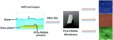
Nanostructured double hydrophobic poly(styrene-b-methyl methacrylate) block copolymer membrane manufactured via a phase inversion technique

Madhavan Karunakaran*, Rahul Shevate and Klaus-Viktor Peinemann
Advanced Membranes and Porous Materials Center, 4700 King Abdullah University of Science and Technology (KAUST), Thuwal 23955-6900, Kingdom of Saudi Arabia. E-mail: madhavan.karunakaran@kaust.edu.sa

Received 26th January 2016 , Accepted 9th March 2016

First published on 11th March 2016


Abstract

In this paper, we demonstrate the formation of nanostructured double hydrophobic poly(styrene-b-methyl methacrylate) (PS-b-PMMA) block copolymer membranes via a state-of-the-art phase inversion technique. The nanostructured membrane morphologies are tuned by different solvent and block copolymer compositions. The membrane morphology has been investigated using FESEM, AFM and TEM. Morphological investigation shows the formation of both cylindrical and lamellar structures on the top surface of the block copolymer membranes. The PS-b-PMMA, with an equal block length (PS160 K-b-PMMA160 K), exhibits both cylindrical and lamellar structures on the top layer of the asymmetric membrane. All membranes fabricated from PS160 K-b-PMMA160 K show incomplete pore formation in both cylindrical and lamellar morphologies during the phase inversion process. However, the PS-b-PMMA (PS135 K-b-PMMA19.5 K) block copolymer, with a short PMMA block, allowed us to produce open pore structures with ordered hexagonal cylindrical pores during the phase inversion process. The resulting PS-b-PMMA nanostructured block copolymer membranes have pure water flux from 105–820 L m−2 h bar and 95% retention of PEG50 K.


Introduction

A block copolymer (BCP) has been widely used for the preparation of highly ordered nanoporous membranes.1–3 Such membranes have applications in catalysis, selective separation of proteins, and drug delivery.4–6 A commonly used method to create pores in self-assembled block copolymer films is the etching of sacrificial domains or the extraction of an added homopolymer.7–9 However, these methods require multiple and complicated steps to develop highly ordered nanoporous membranes. To overcome the complicated steps involved, we developed in the past a simple approach to produce nanoporous membranes by combining self-assembly of block copolymers and non-solvent induced phase separation (NIPS).10–13 The nanopores are formed during immersion of a concentrated BCP solution in a water bath (non-solvent). NIPS technique is commonly used for large-scale industrial production of porous polymer membranes. Highly ordered nanoporous BCP membranes are produced by the NIPS technique by self-assembling of BCP micelles in solutions prior membrane formation.10 Controlling the BCP membrane morphology is the key challenge, and this can be achieved by choosing appropriate solvents mixture and various type of BCPs.14–16

We have shown previously that this technique can be applied to produce nanoporous membranes using the amphiphilic BCPs (PS-b-PEO and PS-b-P4VP).12,14 Several research groups also demonstrated that this method is viable to produce nanoporous asymmetric BCP membranes continuously. Diblock and triblock BCPs such as PS-b-P2VP,17 P(S-co-I)-b-PDMAEMA,18 PI-b-PS-b-P4VP19 and PS-b-PDMAEMA20 are reported for BCP membrane fabrication by the NIPS method. However, all the membranes were produced from amphiphilic block copolymers, which contain at least one hydrophobic and one or more hydrophilic segment. A hydrophilic P4VP block has been widely used in the di- and triblock copolymers for isoporous membrane formation by NIPS method.14,17,19,21 It was demonstrated that the hydrophilic group plays a crucial role in self-assembly and pore formation during the phase inversion process. In the NIPS method, water (non-solvent) has been commonly used as a precipitant for membrane formation. When a block copolymer cast solution is immersed in a water (non-solvent) bath, the BCP solution undergoes a phase separation. The water first exchange with solvents and migrates into the cylindrical domains of swollen hydrophilic blocks and then solidifies the hydrophobic blocks. Simultaneously, solvent diffuses through the channels formed by the hydrophilic block and the solvent get exchanged in these domains because water possesses a higher compatibility with hydrophilic blocks. The swollen hydrophilic group then retains water and create pores during precipitation process. So far, the continuous use of amphiphilic BCPs for isoporous membrane preparation and their formation mechanism indicates that isoporous membranes can only be generated using amphiphilic block copolymers by NIPS method. In contrast to that, here we use a block copolymer containing double hydrophobic blocks (PS-b-PMMA) for the isoporous membrane formation by NIPS method. We hypothesize that the use of two hydrophobic blocks influences the isoporous membrane formation during the NIPS process. In this study, we show the influence of solvent, block length and manufacturing conditions on the final membrane morphology formed by non-solvent induced phase separation.

Experimental

Materials

Poly(styrene-b-methylmethacrylate) (PS-b-PMMA) copolymers with two different block lengths (PS135 K-b-PMMA19.5 K;PDI = 1.09, PS160 K-b-PMMA160 K;PDI = 1.20), were purchased from Polymer Source, Inc, Canada and used as received. N,N-Dimethyl acetamide (DMAc), dioxane, acetone, acetonitrile (CH3CN), N-methylpyrrolidone (NMP), 1-ethyl-3-methylimidazolium tetrafluoroborate ([EMIM][BF4]), and tetrahydrofuran (THF) were purchased from Sigma-Aldrich and used without any further purification. De-ionised (DI) water was used as a coagulant for the phase inversion process.

Membrane preparation

PS-b-PMMA block copolymer membranes were prepared using two different molecular weights of PS-b-PMMA BCP (PS135 K-b-PMMA19.5 K and PS160 K-b-PMMA160 K). Table 1 shows the different types of solvents and polymer compositions used for membrane preparation. All the polymer solutions were stirred at room temperature (RT) and after 24 h the solutions were cast on a glass plate using a casting knife with a gap height of 200 μm. After an evaporation time of 5, 10 or 20 s the film was immersed into a water bath.
Table 1 Types of BCP and solvent mixture used for the preparation of nanostructured membranes
Sample code BCP (mol. wt.) Solvents Polymer (wt%) Solvent (wt%)
PSMMA-1 PS160 K-b-PMMA160 K DMAc/THF/acetone 16.6 33.4/16.6/33.4
PSMMA-2 PS160 K-b-PMMA160 K NMP/THF/CH3CN 14.5 33.4/21.7/30.4
PSMMA-3 PS160 K-b-PMMA160 K DMAc/acetone/([EMIM][BF4]) 12.3 26.0/61.0/0.7
PSMMA-4 PS135 K-b-PMMA19.5 K DMAc/dioxane/CH3CN 15.0 35.0/25.0/25.0


Instrumental characterization

Dry membranes were analyzed using a Field Emission Scanning Electron Microscope (FESEM; FEI Quanta 200 series). Imaging was carried out at 5 kV accelerating potential with a working distance of 10 mm. The dry membrane samples were mounted on aluminum stubs, using aluminum tape and gold coated before imaging. Block copolymer membrane cross sections were imaged using Transmission Electron Microscope (TEM). All membranes were embedded in a low-viscosity epoxy resin (Agar R1165) and cured at 60 °C for 24 h. About 80 nm ultrathin sections of membranes were prepared by using an ultramicrotome (Leica EM UC6). Images were obtained using a Tecnai 12 (FEI company) operating at 120 keV accelerating potential. The membrane samples were stained with RuO4 vapors before imaging. The ultrathin sections of membrane were first placed on a TEM copper grid and then kept inside a closed bottle containing RuO4 vapors. The membrane samples were removed after 2 h from the bottle and imaged. The Atomic Force Microscopy (AFM) analysis was performed using ICON Veeco microscope in the tapping mode. The tip characteristics were as follows: spring constant 3 N m−1, resonant frequency in the range from 60 to 80 kHz. The block copolymer films were dried, and a small piece of membranes were used to record AFM images. Dynamic Light Scattering (DLS) measurements were taken with a Malvern Zetasizer Nano Series (Nano-ZS) at RT. Solutions of 0.1 g L−1 of block copolymers were dissolved in corresponding membrane forming solvent mixtures and the dilute solutions were used to determine the BCP micelle sizes by DLS technique.

Water flux and retention measurement

The pure water flux for the membranes were measured using Amicon dead end filtration cell at 1 bar N2 pressure. Membranes were cut in to coupons of area about 5 cm2. The permeance was calculated by using the following equation
image file: c6ra02313d-t1.tif
where v and t are the volume of permeate and time to collect it respectively; a is the effective membrane area and; ΔP is the transmembrane pressure. Afterward the molecular weight cut-off of the membranes were measured by filtering a mixture of polyethylene glycol (PEG) with different molecular weights in DI water. The feed and permeate concentrations were monitored by gel permeation chromatography. The rejection ratio R was calculated by using the following equation
image file: c6ra02313d-t2.tif
where Cp and Cf are the PEG concentrations of the permeate solutions and the bulk solutions in the feed side respectively.

Results and discussion

BCP membrane formation by phase inversion

A scheme representing the asymmetric membrane formation by water induced phase inversion is shown in Fig. 1. BCP solutions were prepared with binary or ternary mixture of solvents having at least one or two solvents with high volatility. It can be seen from Table 1, that all the nanostructured membrane forming BCP solutions contained at least one volatile solvents. The volatile solvents THF, acetone or dioxane could be a favourable solvent for one or both the blocks present in the BCP. We have shown earlier that the evaporation time during the membrane formation plays a vital role for the final membrane morphology.12 During the evaporation process following things can happen: (1) ordering/disordering of micelles, (2) change in concentration of BCP at the air-surface interfaces, and (3) condensation of moisture from the humic atmosphere on the membrane surface. Finally, the cast polymer solution is immersed in non-solvent precipitation bath. While preparing the block copolymer membranes by NIPS technique, all the above mentioned stages need to be carefully considered.
image file: c6ra02313d-f1.tif
Fig. 1 Schematic diagram of the asymmetric membrane formation process.

In order to prepare PS-b-PMMA nanostructured membranes, we have chosen DMAc, NMP, THF, dioxane and acetone as good solvents for PS and PMMA blocks, whereas CH3CN and [EMIM][BF4] are poor solvents for PS blocks. All the above solvents used for BCP solution formation are miscible with water. These solvents were chosen based on the Hansen solubility parameters of solvents and the individual polymers are shown in Table 2.22 The final membrane morphology and the solvent compositions were optimized by a trial-and-error method (precipitating the polymer solution in water and cross checking the membrane morphology using SEM and AFM).

Table 2 Hansen solubility parameters for polymers and solvents22
  δD δP δH δ = (δD2 + δP2 + δH2)1/2
PS 18.6 1.0 4.1 19.1
PMMA 18.6 10.5 7.5 22.6
Water 15.6 16.0 42.3 47.8
DMAc 16.8 11.5 10.2 22.3
NMP 18.0 12.3 7.2 22.9
Acetone 15.5 10.4 7.0 19.9
Dioxane 19.0 1.8 7.4 20.5
THF 16.8 5.7 8.0 19.5
Acetonitrile 15.3 18.0 6.1 24.4
[EMIM][BF4] 24.4


Influence of solvent mixtures on membrane morphology

As noted earlier, the solvent system plays a major role in the self-assembly of block copolymers and significantly controls the final membrane morphology. To develop isoporous PS-b-PMMA membranes by the NIPS method, we used different solvent mixtures and block copolymer compositions. Previous studies showed isoporous membranes were prepared using di- or tri- solvent systems.10,12,14 Initially, we prepared membranes using mono- and di- solvent mixtures, however, the morphologies of the PS-b-PMMA membranes did not show an ordered pore morphology (Fig. S1 ESI). Only tri-solvent mixtures showed a self-assembled morphology on the top surface of the PS-b-PMMA membrane. The tri-solvent mixture and the type of block copolymers used to prepare highly ordered nanostructured membranes are reported in Table 1. The different solvent systems and polymer compositions used to prepare membranes are denoted as PSMMA-1, PSMMA-2, PSMMA-3, and PSMMA-4 respectively.

PSMMA-1 membranes were first prepared by dissolving 16.6 wt% of PS160 K-b-PMMA160 K in a mixture of DMAc/acetone/dioxane solvents (Table 1). The BCP solution was cast on the glass plate, and the cast solution was evaporated at 10 and 20 s time intervals and then immersed in the water bath. Fig. 2 shows the SEM images of PSMMA-1 membranes produced by NIPS method. Fig. 2a shows that the PS-b-PMMA block copolymer formed a very well-ordered hexagonal cylindrical structure at 10 s evaporation time. However, the same block copolymer solution evaporated for 20 s (Fig. 2b) during membrane preparation showed well-oriented lamellar morphology on the top surface of the membrane. Fig. 2a and b shows two different morphologies that were obtained using the same PSMMA-1 solution composition; only the evaporation time was changed from 10 to 20 s and the membrane structure transformed from hexagonal cylinder to order lamellar morphology. This reveals that the solvent evaporation (acetone and THF) and the evaporation time (10 and 20 s) is important for the final membrane morphology.


image file: c6ra02313d-f2.tif
Fig. 2 FESEM images of PSMMA-1 membrane manufactured by phase inversion process (a) top surface (10 s evaporation), (b) top surface (20 s evaporation), (c) cross section (10 s evaporation), and (d) cross section (20 s evaporation).

The Fig. 2c and d shows the cryo-fractured cross-section SEM images of the dried PSMMA-1 block copolymer membranes. In both cases, the membrane shows a sponge-like porous substructure underneath the ordered skin asymmetric top layer. This confirms that the solvent-water mixing–demixing process occurred during the immersion of BCP solution in water. The top surface of the membrane at higher magnification (inset of Fig. 2a and b) shows very well ordered cylindrical and lamellar morphology. However, the pores of the membranes are incompletely opened. Similarly, the PS160 K-b-PMMA160 K BCP dissolved in NMP/THF/acetonitrile (PSMMA-2) solvent mixture was cast on a glass plate and evaporated for 10, 15 and 20 s before immersion in water. Fig. 3 shows cylindrical, mixed cylindrical-lamella and lamellar morphologies for PS-b-PMMA BCP membranes at 10, 15 and 20 s evaporation time intervals. The thermodynamically unstable cylinder morphology shifts to the stable lamellar morphology during evaporation of solvent. Membranes with various ordered morphologies were observed (Fig. 3) at different evaporation times. However, in all the cases only a few open pores were obtained. These results indicates that the hydrophobic PS-b-PMMA BCP can self-assemble and forms an ordered morphology with closed nanopores on the top surface of the membranes during the NIPS method. This scenario is different for PS-b-P4VP amphiphilic block copolymers which showed a very ordered morphology with open pore structure.21 This demonstrates the crucial role of the hydrophilic block (PVP) in pore formation during the NIPS method.


image file: c6ra02313d-f3.tif
Fig. 3 FESEM images of PSMMA-2 (top surface) membrane manufactured by phase inversion process with different evaporation time (a) 10 s, (b) 15 s, and (c) 20 s.

The BCPs used here contain two hydrophobic blocks such as PS and PMMA which are not compatible with the water, leading to a closed pore structure during the phase inversion process. It can be seen from all the above membrane surfaces (Fig. 2 and 3) that highly ordered hexagonal cylindrical and lamellar morphologies were formed with PS160 K-b-PMMA160 K BCP. However, pore formation was incomplete for both hexagonal cylinder and lamella morphologies.

We believe that an ordered open porous structure would be generated by introducing a pore generating liquid such as an ionic liquid (IL) to the BCP solution. Xing et al.23,24 reported that a higher porosity is obtained when volatile solvents are replaced by ionic liquids in the casting solution. ILs have been used as self-assembling media for tuning the block copolymer morphologies.25,26 Considering the above properties of ILs, we prepared PS160 K-b-PMMA160 K BCP solution containing about 0.7 wt% of IL ([EMIM][BF4) in DMAc/acetone mixtures (PSMMA-3) and prepared membranes by precipitation in water. Interestingly the IL co-solvent added PS-b-PMMA BCP membrane showed ordered spheres with nanopores formed between the spheres. Fig. 4a and b shows the top surface SEM images of membrane prepared at 10 and 20 s evaporation time. The arrangement of spheres did not change much with evaporation time, but no pores were formed at 20 s evaporation time. Some macrovoids are formed on the bottom of the membrane (Fig. 4d), because of water diffusion and solvent/IL exchange during water induced phase separation. Even in the presence of IL the top layer has less number of opened pores at 10 s evaporation time, but at 20 s evaporation time no pores were formed due to formation of skin nonporous dense layer by the evaporation of the highly volatile (acetone) solvent during the membrane formation. The addition of pore forming ILs to the BCP solution did not form an open pore structure in the final membrane morphology. Henceforth, we chose a PS-b-PMMA BCP having a smaller PMMA block length (PS135 K-b-PMMA19.5 K) for membrane preparation. About 15 wt% of PS135 K-b-PMMA19.5 K was dissolved in DMAc/dioxane/acetonitrile solvent mixture and the membrane (PSMMA-4) was prepared by immersing in water after 10 s evaporation time. The prepared PSMMA-4 membrane has an ordered open porous structure (Fig. 5). The average pore diameter for PSMMA-4 membrane is about 45 nm (Table 3). The pore sizes of the PSMMA-4 membrane is slightly larger than the membranes obtained from PS160 K-b-PMMA160 K BCP. The PSMMA-4 membrane showed an isoporous structure with pore sizes in the range from 20 to 60 nm. However, some larger pores were also observed in the SEM image (Fig. S2d) with pore sizes in the range from 80 to 100 nm. The result suggests that PS-b-PMMA with smaller PMMA block length produce highly ordered open porous structure by the NIPS method. The cryo fractured cross-section SEM images of the PSMMA-4 membrane (Fig. 5c) show a sponge-like structure underneath the ordered nanoporous layer. The AFM image of PSMMA-4 membrane (Fig. 5d) also confirms the formation of self-assembled porous morphology on the top surface of the membrane. From the morphological investigation we found that the ordered open porous structure can be obtained while using a block copolymer with smaller PMMA block. The mean pore diameter and pore size distribution for the membranes were obtained from SEM images and the values are given in Table 3. All the membranes show different pore size distributions. The mean pore diameter observed for PSMMA-2 membrane is 16 nm with a standard deviation of 5.9 nm. The PSMMA-4 membrane prepared from PS135 K-b-PMMA19.5 K block copolymer showed a larger pore diameter (45 nm) with a standard deviation of 14.8 nm; these values are relatively high in comparison with other PS-b-PMMA membranes. The high standard deviation value indicates the broad pore size distribution. The pore morphologies and histogram of pore size distribution are shown in Fig. S2 (ESI). In order to see the effect of micelles size on the pore diameter of the final membrane morphology, we measured the micelles size in polymer solutions by DLS technique and the data obtained are summarized in Table 3. The micelle diameter (Z-average) values for the PS160 K-b-PMMA160 K in all solvents mixtures were in the range from 29 to 43 nm, whereas the micelles size for PS135 K-b-PMMA19.5 K was 16.7 nm. In general, the micelle structures and sizes are determined by a balance between solventphobic and solventphilic interactions and the relative block sizes. The larger micelle diameter values for PS160 K-b-PMMA160 K block copolymer may be due to the larger block lengths of both the blocks. In particular, the PSMMA-3 membrane solutions showed very high Z-average values this is attributed to the solvophobic effect of IL on both the PS and PMMA blocks. In the case of PSMMA-4 solution, the smaller micelle size were observed because of presence of smaller PMMA block (PS135 K-b-PMMA19.5 K). For comparison the average micelle size and pore size are given in Table 3. In a case of PSMMA-1, 2, and 3, the trend shows the larger micelle diameter would lead to larger pore size, however, the PSMMA-4 differs completely from this trend. PSMMA-4 showed a smaller micelle size (16.68 nm) with an average pore diameter of 45 nm. The larger pore diameter from the smaller micelle is due to the smaller block length of BCP (PS135 K-b-PMMA19.5 K) used to prepare the PSMMA-4 membrane which is different than the BCP (PS160 K-b-PMMA160 K) used to prepare PSMMA-1, 2 and 3 membranes. By comparing two different block lengths of BCP, we observed that larger block length formed larger micelles but lead to a small pore diameter in the final membranes and smaller block length formed smaller micelles which gives rise to a larger pore diameter. The cross-sections of all the PS-b-PMMA membranes were microtomed and imaged using TEM. Before imaging the membranes were selectively stained with RuO4, which stains only the PS block of the copolymer.27 It can be seen from Fig. 6, that the spherical micelles formed in the block copolymer solution were observed below the skin selective top layer. All the spherical micelles showed a dark spot surrounded by bright circles. Since the staining agent RuO4 only stains the PS block, the dark spot is supposed to be the PS core, and a bright circle surrounded by the PS core is the PMMA corona.


image file: c6ra02313d-f4.tif
Fig. 4 FESEM images of PSMMA-3 membrane manufactured by phase inversion process (a) top surface (10 s evaporation), (b) top surface (20 s evaporation), (c) AFM image of top surface of membrane (10 s evaporation), and (d) FESEM bottom layer of membrane (10 s evaporation).

image file: c6ra02313d-f5.tif
Fig. 5 FESEM images of PSMMA-4 membrane manufactured by phase inversion process at 10 s evaporation time (a) and (b) top surface at 1 μm and 300 nm, (c) cross section, and (d) AFM image (top surface).
Table 3 BCP micelles size, membrane pore distributions, water flux and retention properties
Membranesa Micelle size in solution Z-average (d; nm) Mean pore diameter (nm) σ (nm) Flux (L m−2 h bar) PEG50 K retention (%)
a Membranes prepared at evaporation time 10 s; σ standard deviation of pore diameter.
PSMMA-1 35.98 19 5.6 450 56
PSMMA-2 29.68 16 5.9 105 95
PSMMA-3 43.26 22 7.4 550 51
PSMMA-4 16.68 45 14.8 820 10


image file: c6ra02313d-f6.tif
Fig. 6 TEM images of PSMMA membranes cross-section manufactured by phase inversion process, (a) PSMMA-1, (b) PSMMA-2, (c) PSMMA-3, and (d) PSMMA-4.

Water flux and retention measurement

The water flux of membranes (5 cm2) was tested in an Amicon cell at 1 bar feed pressure. The molecular weight cut-off of the membranes were measured by filtering a mixture of polyethylene glycol (PEG) with different molecular weights in DI water. The feed and permeate concentrations were monitored by gel permeation chromatography. Water fluxes and PEG retention values for all the membranes are shown in Fig. 7. The graph shows that all the membranes had high water fluxes in the range from 105 to 820 L m−2 h bar. Significant rejection of PEG50 K (95% retention) was obtained for the PSMMA-2 membrane but this membrane had a low water flux of around 100 L m−2 h bar the low water flux is due to the lower number of open pores on the top surface of the membranes which well agrees with SEM images. The mean pore diameter and PEG50 K retention values for all the membranes are summarized in (Table 3). The mean pore diameter obtained for this membrane is 16 nm which is small compared to other membranes which might be the reason for the high rejection of PEG50 K. The PSMMA-1 and PSMMA-3 membrane had water fluxes of 450 and 550 L m−2 h bar with retentions of 50% and 56% PEG50 K. Furthermore, the PSMMA-4 membrane with a well opened pore structure had a very high water flux of about 820 L m−2 h bar, however, the membrane had low (10%) PEG50 K retention. The mean pore diameter for PSMMA-4 membrane is 45 nm which is larger than the pore sizes of PSMMA-2 membrane. Fig. S2d shows that the majority of pores were observed in the range from 20 to 60 nm and there were some largers pores observed in the range from 80 to 100 nm which provides the passages for the PEG molecules. The very low PEG50 K retention indicates the passage of PEG molecules through the larger pores present in the selective layer of the membrane.
image file: c6ra02313d-f7.tif
Fig. 7 A plot of PEG retention vs. PEG molar mass for PS-b-PMMA membranes.

Conclusion

In this study, we demonstrated the feasibility of the formation of nanoporous hydrophobic PS-b-PMMA membranes by water induced phase separation. The PS160 K-b-PMMA160 K block copolymer membrane exhibits both cylindrical and lamellar morphologies. Here, we achieved both the cylindrical and lamellar morphologies just by changing the evaporation time before precipitation in water. The PS160 K-b-PMMA160 K membrane produced by the NIPS process had an ordered morphology, however, low porosity was observed from the microscopic analysis. The block copolymer having lower PMMA block length showed a hexagonal cylindrically ordered isoporous structure. The membranes showed high water flux with low PEG retention. The low PEG retention is due to the formation of larger pores (80–100 nm) in the selective skin layer of the membrane. The PS-b-PMMA block copolymer solution during membrane formation was highly sensitive to air/surface interaction which creates larger pores along with the ordered isopores in the final membrane surfaces. However, this work confirms that nanostructured PS-b-PMMA block copolymer membranes could be manufactured by water induced phase separation.

Acknowledgements

This research was supported by King Abdullah University of Science and Technology (KAUST).

References

  1. S. P. Nunes and A. Car, Ind. Eng. Chem. Res., 2013, 52, 993–1003 CrossRef CAS.
  2. R. M. Dorin, H. Sai and U. Wiesner, Chem. Mater., 2014, 26, 339–347 CrossRef CAS.
  3. S. Y. Yang, I. Ryu, H. Y. Kim, J. K. Kim, S. K. Jang and T. P. Russell, Adv. Mater., 2006, 18, 709–712 CrossRef CAS.
  4. R. Hilke, N. Pradeep, P. Madhavan, U. Vainio, A. R. Behzad, R. Sougrat, S. P. Nunes and K. V. Peinemann, ACS Appl. Mater. Interfaces, 2013, 5, 7001–7006 CAS.
  5. H. Yu, X. Qiu, S. P. Nunes and K. V. Peinemann, Angew. Chem., Int. Ed., 2014, 53, 10072–10076 CrossRef CAS PubMed.
  6. G. Jeon, S. Y. Yanga and J. K. Kim, J. Mater. Chem., 2012, 22, 14814–14834 RSC.
  7. X. Ma, X. Sui, Z. Zhang, C. Li, N. Zhang, A. Chen, Q. Xie and L. Gao, RSC Adv., 2015, 5, 98105–98109 RSC.
  8. S. Y. Yang, J. Park, J. Yoon, M. Ree, S. K. Jang and J. K. Kim, Adv. Funct. Mater., 2008, 18, 1371–1377 CrossRef CAS.
  9. H. Uehara, M. Kano, H. Tanaka, S. Kato, H. Masunaga and T. Yamanobe, RSC Adv., 2014, 4, 42467–42477 RSC.
  10. S. P. Nunes, R. Sougrat, B. Hooghan, D. H. Anjum, A. R. Behzad, L. Zhao, N. Pradeep, I. Pinnau, U. Vainio and K. V. Peinemann, Macromolecules, 2010, 43, 8079–8085 CrossRef CAS.
  11. S. P. Nunes, A. R. Behzad, B. Hooghan, R. Sougrat, M. Karunakaran, N. Pradeep, U. Vainio and K. V. Peinemann, ACS Nano, 2011, 5, 3516–3522 CrossRef CAS PubMed.
  12. M. Karunakaran, S. P. Nunes, X. Qiu, H. Yu and K. V. Peinemann, J. Membr. Sci., 2014, 453, 471–477 CrossRef CAS.
  13. D. S. Marques, U. Vainio, N. M. Chaparro, V. M. Calo, A. R. Behzad, J. W. Pitera, K. V. Peinemann and S. P. Nunes, Soft Matter, 2013, 9, 5557–5564 RSC.
  14. S. P. Nunes, M. Karunakaran, N. Pradeep, A. R. Behzad, B. Hooghan, R. Sougrat, H. He and K. V. Peinemann, Langmuir, 2011, 27, 10184–10190 CrossRef CAS PubMed.
  15. S. Rangoua, K. Buhr, V. Filiz, J. I. Clodt, B. Lademann, J. Hahn, A. Jung and V. Abetz, J. Membr. Sci., 2014, 451, 266–275 CrossRef.
  16. J. Hahn, V. Filiz, S. Rangou, J. Clodt, A. Jung, K. Buhr, C. Abetz and V. Abetz, J. Polym. Sci., Part B: Polym. Phys., 2012, 51, 281–290 CrossRef.
  17. A. Jung, S. Rangou, C. Abetz, V. Filiz and V. Abetz, Macromol. Mater. Eng., 2012, 297, 790–798 CrossRef CAS.
  18. C. Horenz, C. Pietsch, A. S. Goldmann, C. Barner-Kowollik and F. H. Schacher, Adv. Mater. Interfaces, 2015, 2, 1500042–1500053 Search PubMed.
  19. W. A. Phillip, R. M. Dorin, J. Werner, E. M. V. Hoek, U. Wiesner and M. Elimelech, Nano Lett., 2011, 11, 2892–2900 CrossRef CAS PubMed.
  20. F. H. Schacher, M. Ulbricht and A. H. E. Müller, Adv. Funct. Mater., 2009, 19, 1040–1045 CrossRef CAS.
  21. K. V. Peinemann, V. Abetz and P. F. W. Simon, Nat. Mater., 2007, 6, 992–996 CrossRef CAS PubMed.
  22. Hansen Solubility Parameters: A User's Handbook, ed. C. M. Hansen, CRC Press, 2nd edn, 2007 Search PubMed.
  23. D. Y. Xing, N. Peng and T. S. Chung, Ind. Eng. Chem. Res., 2010, 49, 8761–8769 CrossRef CAS.
  24. D. Y. Xing, N. Peng and T. S. Chung, J. Membr. Sci., 2011, 3, 87–97 CrossRef.
  25. P. M. Simone and T. P. Lodge, Macromol. Chem. Phys., 2007, 208, 339–348 CrossRef CAS.
  26. J. M. Virgili, A. J. Nedoma, R. A. Segalman and N. P. Balsara, Macromolecules, 2013, 43, 3750–3756 CrossRef.
  27. J. S. Trent, J. I. Scheinbeim and P. R. Couchman, Macromolecules, 1983, 16, 589–598 CrossRef CAS.

Footnote

Electronic supplementary information (ESI) available. See DOI: 10.1039/c6ra02313d

This journal is © The Royal Society of Chemistry 2016