
A promising anode material for sodium-ion battery with high capacity and high diffusion ability: graphyne and graphdiyne†
Zhenming Xua,
Xiaojun Lv*a,
Jie Lia,
Jiangan Chenb and
Qingsheng Liuc
aSchool of Metallurgy and Environment, Central South University, Changsha 410083, China. E-mail: 15216105346@163.com
bFaculty of Resource and Environmental Engineering, Jiangxi University of Science and Technology, Ganzhou 341000, China
cFaculty of Metallurgical and Chemical Engineering, Jiangxi University of Science and Technology, Ganzhou 341000, China
First published on 2nd March 2016
Abstract
An investigation of the energetics and dynamics properties of sodium adsorption on graphyne and graphdiyne has been carried out by first-principles calculations. Graphyne (GY) and graphdiyne (GDY) is the single atomic layer structure of carbon six-member rings connected by one and two acetylenic linkages, respectively. Our calculated results indicate that a novel atomic hollow structure of graphyne and graphdiyne made up of sp- and sp2-hybridized carbon atoms reinforces not only the Na storage capacity but also the Na diffusion. For GY and GDY, the maximum sodium storage concentration is NaC4 and NaC3, respectively, far exceeding the upper limit of Na insertion into graphite to form the stage-II compound NaC12 and being also superior to the case of Li inserting into graphite to form LiC6. By only overcoming a smaller energy barrier of about 0.4 eV, Na ions can easily achieve two-dimensional diffusion on GY and GDY plane. Excellent performances of the sodium storage capacity and sodium diffusion ability make graphyne and graphdiyne promising candidates for the anode material used in sodium-ion batteries.
1. Introduction
On account of the maturity of commercial lithium-ion battery (LIB) technologies, they have been widely applied in various applications such as portable and telecommunication electronic devices.1–5 However, facing with the increased development of electric vehicles, power backups and other large-scale energy storage equipment, the cost and safety concerns of Li-ion batteries must be reviewed. Recently, intense attention has been paid to the sodium-ion batteries (SIBs) due to their outstanding advantages of low material cost and abundant resources widely existing in the sea, compared to commercial lithium-ion batteries (LIBs).6–9 Therefore, SIBs are the promising alternatives to LIBs to meet the demands of large-scale energy storage applications. So far, considerable efforts have been dedicated to search for suitable anode materials for SIBs, such as carbon-based compounds,10–12 TiO2 (ref. 13–17) oxides and alloys Sn–Sb18–20 have been developed and successfully synthesized.Different from the standard anode materials in current commercial lithium-ion batteries, graphite is not suitable for the sodium based system. As Na atom hardly inserts into graphite to form the low stage intercalation compound (NaC12),21–25 and accordingly graphite have a quite low sodium intercalation capacity of 35 mA h g−1.26 Therefore, in pursuit of improvement for both storage capacity and rate capability, explorations for anode materials are not only limited to the traditional nongraphitic carbonaceous materials, such as coke,27 carbon black,28 template carbon,11,29 but also turned to the innovative electrode materials, such as graphene,10,30 hollow carbon nanowires12 and nanospheres31 etc.
Recently, a new two-dimensional carbonaceous candidate, graphdiyne (GDY), composed of sp- and sp2-hybridized carbon atoms, has been firstly synthesized by Haley et al.32 and subsequent large area synthesis (3.61 cm2) on the copper surface by means of a cross-coupling reaction have been carried out by Y Li et al.33 Graphyne (GY) and graphdiyne (GDY) is the single atomic layer structure of carbon six-member rings connected by the acetylenic linkages (–C![[triple bond, length as m-dash]](https://www.rsc.org/images/entities/char_e002.gif) C–), known as the most stable carbon allotropes artificially synthesized. By changing the number of acetylene linkage between two carbon six-member rings (defined as n), a series of sp–sp2 hybrid structure can be obtained, called as graph-n-yne.34 When n = 0, graphene is obtained; when n = 1, two carbon six-member rings are joined by the uniformly distributed acetylenic linkages (–CC–), corresponding to graphyne (GY); when it comes to n = 2, two acetylenic linkages (–CC–CC–) locate between two adjacent carbon six-member rings, and the corresponding configuration is so-called graphdiyne (GDY). For GY and GDY, on one hand, many theoretical calculation works33–42 have forecasted that the triangular porous structure, asymmetrically conjugated π electrons of GY and GDY provide a 3D channel for lithium diffusion and unique triangular occupation model for Li atoms: every triangular pore accommodates three Li atoms and the theoretical maximum Li storage capacity of monolayer GY and GDY can be as high as 558 and 744 mA h g−1 (LiC4 and LiC3),37,39,41 respectively, which is twice that of the commercial graphite system (372 mA h g−1, LiC6).21,25,43–46 On the other hand, experimental works for lithium storage in graphdiyne (GDY) have been successfully carried out,42,47 and experimental results show outstanding performances of high capacity 520 mA h g−1 after 400 cycles and long cycle lives for lithium storage in graphdiyne. All these evidences demonstrate a fact that GY and GDY is the promising candidate anode material for next generation lithium-ion batteries (LIBs).
C–), known as the most stable carbon allotropes artificially synthesized. By changing the number of acetylene linkage between two carbon six-member rings (defined as n), a series of sp–sp2 hybrid structure can be obtained, called as graph-n-yne.34 When n = 0, graphene is obtained; when n = 1, two carbon six-member rings are joined by the uniformly distributed acetylenic linkages (–CC–), corresponding to graphyne (GY); when it comes to n = 2, two acetylenic linkages (–CC–CC–) locate between two adjacent carbon six-member rings, and the corresponding configuration is so-called graphdiyne (GDY). For GY and GDY, on one hand, many theoretical calculation works33–42 have forecasted that the triangular porous structure, asymmetrically conjugated π electrons of GY and GDY provide a 3D channel for lithium diffusion and unique triangular occupation model for Li atoms: every triangular pore accommodates three Li atoms and the theoretical maximum Li storage capacity of monolayer GY and GDY can be as high as 558 and 744 mA h g−1 (LiC4 and LiC3),37,39,41 respectively, which is twice that of the commercial graphite system (372 mA h g−1, LiC6).21,25,43–46 On the other hand, experimental works for lithium storage in graphdiyne (GDY) have been successfully carried out,42,47 and experimental results show outstanding performances of high capacity 520 mA h g−1 after 400 cycles and long cycle lives for lithium storage in graphdiyne. All these evidences demonstrate a fact that GY and GDY is the promising candidate anode material for next generation lithium-ion batteries (LIBs).
Inspired by previous works of pursuing GY and GDY as the excellent anode material for lithium-ion batteries (LIBs), a question hanging on our heads that whether it is possible to applying GY and GDY to the fields of sodium-ion batteries (SIBs). To the best of our knowledge, to date, hardly any experimental effort of research on sodium storage on GY and GDY has been reported, even for theoretical calculation. To provide guidance for future experimental works, in this paper, we have firstly performed the first-principles calculations to pore the energetics and dynamics of sodium in GY and GDY.
2. Methods and computational details
As we know DFT hardly gives correct description for the interlayer van der Waals interaction of graphite system.22,48 So our calculations for energetics and dynamics of sodium in GY and GDY were based on the dispersion-corrected density functional theory (DFT-D)49–51 provided by the CASTEP code.52 According to the recommendation that DFT-D including the vdW weak interactions can be competent for the vdW interaction on the bonding of Li-GD and Li-diffusion.40 Li and Na is the kin element with a certain similarity. Therefore, in this work, Grimme's DFT-D2 approach53 was applied to describe the weak interactions of carbon layers. PBE54 exchange function of GGA was chosen for our calculations and ultrasoft pseudo potentials (USPP) introduced by Vanderbilt55 was employed for all the ion–electron interactions. Here, C 2s22p2 electrons and Na 2p63s1 electrons were explicitly regarded as the valence electrons. Convergence with respect to both energy cutoff and k-point mesh has been tested strictly. Considering convergence tests and computational efficiency comprehensively, an energy cutoff of 500 eV was chosen to ensure that the total energies were converged within 1 × 10⁻⁶ eV per atom. For the Brillouin zone sampling, we carried out 4 × 4 × 2 and 6 × 6 × 2 for GY and GDY by using the Monkhorst–Pack methods.56In order to determine the most-stable configuration of Na-GY and Na-GDY models, atom and cell optimizations were performed beforehand by using the total energy minimization methods. The total-energy difference is within 10−6 eV per atom, the maximum force is within 0.01 eV Å−1, the maximum stress is within 0.01 GPa and the maximum atom displacement is within 10−4 Å. Two-dimensional periodic boundary condition was introduced to the calculations for GY and GDY. Moreover, a vacuum region of 15 Å was also applied in the direction perpendicular to the GY and GDY plane to eliminate the interactions between adjacent conformations. For bulk GY and GDY, (2 × 2) supercells containing two GY and GDY layers with an AB stacking sequence were constructured. The stability of Na-GY and Na-GDY system can be estimated by their according sodium average adsorption energy (ΔE). The average adsorption energies were calculated by the following equation:25 ΔE = [ENa-GY or GDY − (EGY or GDY + ENa)]/n, where ENa-GY or GDY, EGY or GDY and ENa is total energies of the Na-GY or Na-GDY system, the GY, GDY and Na in its pure bulk, respectively, n is the total number of Na atom in Na-GY or Na-GDY system. As for total energy calculations of ENa-GY or GDY and EGY or GDY, full optimizations of the fractional coordinates and the lattice parameters were performed by means of total energy minimization.57
3. Results and discussions
3.1 Na adsorption on GY and GDY
Firstly, we relaxed the (2 × 2) supercell for single-layer GY and GDY, as depicted in Fig. 1. The optimized lattice constant a is 6.89 and 9.45 Å, respectively for single-layer GY and GDY, which is in good agreement with the results of 6.86 and 9.48 Å from other DFT calculations.37,41 The average bond length between the sp2-hybridized C atoms is 1.417 and 1.424 Å, respectively for single-layer GY and GDY, close to that in graphene. The average distance of C(sp)C(sp) triple bond is 1.217 and 1.227 Å, and C–C bond connecting sp- and sp2-hybridized carbon atoms has an average length of 1.42 and 1.402 Å, respectively for single-layer GY and GDY. In addition, a special C(sp)–C(sp) bond in the middle of acetylenic linkages (–CC–CC–) of GDY is 1.343 Å, which is obviously shorter than that between two sp2-hybridized carbon atoms but longer than that in sp-hybridized. Our calculated results show that GDY is energetically unfavorable than GY by about 0.078 eV per atom, indicating its lower synthetic feasibility than GY.
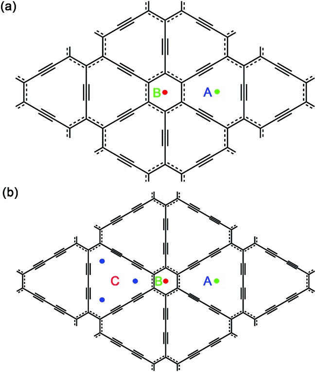 | ||
| Fig. 1 Schematic plots for the single-layer graphyne (a) and graphdiyne (b) of a (2 × 2) supercell and possible Na adsorption sites. | ||
Then, we investigated one Na atom adsorption on single-layer GY and GDY. Referring to some previous analogous works, Li atoms preferentially adsorb over the center of hexagon and triangular-like pores (hollow sites) on GY and GDY planes.33,37,39–41 Therefore, for GY, two typical hollow adsorption sites were considered: above the center of triangular-like pores (denoted as A) and above the center of hexagons (denoted as B), as depicted in Fig. 1a. While for GDY, three typical hollow adsorption sites were considered as: A site above the center of triangular-like pores, B site above the center of hexagons and C site above the corner of triangular-like pores, as shown in Fig. 1b. In this work, the structural distortion resulted from Na adsorption on both hollow sites of GY and GDY plane was found to be slight and negligible. Viewed from Table 1, for GY, the adsorption energy of one Na adsorption at the B site was calculated to be −1.37 eV, with an adsorption height of 2.28 Å. Here, the adsorption height is defined as the distance between the adsorbate and host-layer plane. Similar to the case of B site, Na adsorbed at the A site is also excluded out the GY plane, with a lower adsorption energy of −1.93 eV and an adsorption height of 1.68 Å. Therefore, the Na atoms preferentially adsorb above the center of triangular-like pores (A site) rather than the center of hexagons (B site), consistent with that case of Li adsorption on the GY.34,38,39,41 Seen from Table 1, for GDY, a negative adsorption energy (−2.19 eV) of one Na adsorption at the center of triangular-like pores (A site) within the GDY plane, which is different from than case of one Na adsorption above the center of triangular-like pores of GY plane. Na atom also can be absorbed above the center of hexagons (B site) of GDY plane, with a higher adsorption energy of −1.76 eV and an adsorption height of 2.3 Å. While for C site in GDY (Fig. 1), we find that after structural relaxation, the initial Na atom at C site finally move to the A site, indicating the corner of triangular-like pore (C site) of GDY is energetically unfavorable for one Na atom adsorption. Interestingly, this case is clearly different from that case of a single Li adsorption on the GDY.37 The higher adsorption strength of Na on GY and GDY can be attributed to the special triangular-like pore structure and sp-hybridization of carbon atoms in GY and GDY.
| Carbon layer number | Na loading number | Adsorption site | Adsorption height | Adsorption energy | Maximum storage configuration | |
|---|---|---|---|---|---|---|
| GY | 1 | 1 | B | 2.28 | −1.37 | NaC12 |
| 1 | 1 | A | 1.68 | −1.93 | NaC12 | |
| 1 | 2 | A | 1.82 | −2.64 | NaC6 | |
| 2 | 6 | A and B | 1.92 | −1.86 | NaC4 | |
| GDY | 1 | 1 | A or C | 0 | −2.19 | NaC18 |
| 1 | 1 | B | 2.3 | −1.76 | NaC18 | |
| 1 | 6 | C | 1.96 | −1.30 | NaC3 | |
| 2 | 6 | C | 2.03 | −2.03 | NaC6 |
To explore the maximum sodium storage capacity for GY and GDY under the condition of keeping structural stability, we have calculated several cases of Na atoms adsorption on single and double-layer GY and GDY. The calculated results listed in Table 1 indicate that for single-layer GY, the stable configuration for maximum sodium storage is NaC6, in which Na is located above the center of triangular-like pores (A site) with a lower average adsorption energy of −2.64 eV per Na and an average adsorption height of 1.82 Å. While for case of double-layer GY with AB stacking pattern, the optimized Na-intercalated double-layer GY is depicted in Fig. 2a, which responds to the maximum sodium storage configuration (NaC4). Here, Na atoms are simultaneously located above the center of triangular-like pores (A site) and above the center of hexagons (B site) with a lower average adsorption energy of −1.86 eV per Na and an average adsorption height of 1.92 Å. In addition, the distance of Na inserted double-layer GY increases only by 16% from 3.3 to 3.84 Å, indicating the structural stability of charge and discharge process.
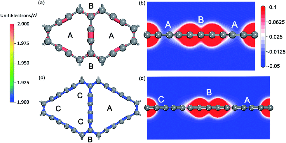 | ||
| Fig. 2 Charge density of GY (a) and GDY (c) monolayers (in electrons per Å3), electrostatic potential projected on a slice containing both A and B sites and perpendicular to the single GY (b) and GDY (d) monolayers. | ||
For single-layer GDY, it is found that every triangular-like pore can furthest store three Na atoms at three symmetric corners, making a unique Na occupation pattern called as a triangular pattern and the stable configuration for maximum sodium storage responds to NaC3. The average adsorption energy for this occupation configuration was computed to be −1.3 eV per Na, with an average adsorption height of 1.96 Å. For double-layer GDY with AB stacking pattern, the configuration with maximum sodium storage capacity not losing structural stability corresponds to NaC6, as depicted in Fig. 2b. The distance of Na inserted double-layer GDY increases by 20% from 3.5 to 4.2 Å. The corresponding average adsorption energy is −2.03 eV per Na, and average adsorption height is 2.03 Å. All these adsorption energies for several Na atoms adsorption on GDY plane are far larger than the cohesive energy (0.149 eV) of Na bulk, indicating that the clustering of Na atoms could be avoidable since it is energetically prohibited. It is noteworthy that while three C sites (Fig. 1b) of triangular-like pore in GDY are fully occupied, these three Na atoms all extrude out of GDY plane and separate from each other, which is different from that case of one Na adsorption in the center of GDY plane. Our calculations explicitly verified that three Na adsorption above the double-layer GDY plane forming NaC6 is more favorable than the corresponding configuration (NaC3) with three Na atoms located above the single-layer GDY by 0.26 eV per Na. It is due to the stronger Coulomb attractive interactions between positively charged Na ions and negatively charged host layers, induced by substantial charge transfer from Na to GDY plane for both hollow sites, as revealed by the Hirshfeld population analysis of Na losing average 0.38 and 0.29e, respectively for NaC6 and NaC3 system.
For the ionic bonded Na-GY and Na-GDY adsorption systems, the adsorption energy and adsorption height is the result of interaction balance of the electrostatic attraction between positively charged Na ions and negatively charged GY and GDY host layer and the short-range electron repulsion among positive Na ions. Therefore, the A site is preferentially energetic for one Na (positively charged) adsorption than the B and C site. As evidences depicted in Fig. 3, the plane polt of negative charge density of GY and GDY containing both A, B and C sites and the electrostatic potential slices perpendicular to GY and GDY plane can further confirm above viewpoints. Viewed from Fig. 3a and c, we find the negative charges are mainly localized between the sp-hybridized CC triple bonds, which determines the adsorption strength between host layers and Na ions. From Fig. 3b and d, it can be clearly seen that both A and B sites are located into potential valleys, with the lowest and second lowest negative electrostatic potential, respectively. While the C site is not in potential valley, consistent with the fact that one Na adsorption on the C site is energetically unfavorable. Thus, positively charged Na ion energetically favors these locations with the lowest electrostatic potential. In addition, the electrostatic potential profiles also reflect the distinction of adsorption height of A and B site. With all these evidences, we can conclude that similar to the case of lithium storage in GY and GDY to form the ceiling compound of LiC4 (ref. 41) and LiC3,37,40 the maximum sodium storage capacity for GY and GDY is NaC4 and NaC3, respectively, which far exceeds the ceiling of Na inserting into graphite to form stage-II compound of NaC12 (ref. 21 and 25) and is also superior to that case of Li inserting into graphite to form LiC6.43,58
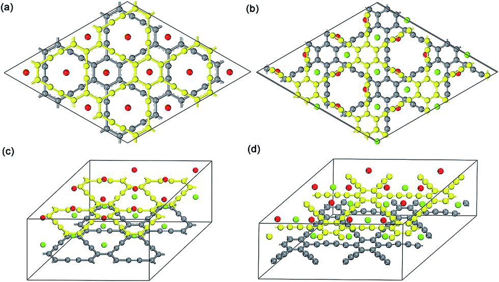 | ||
| Fig. 3 Top view and 3D view of 2 × 2 optimized Na-intercalated double-layer GY and GDY compound NaC4 (a and c) and NaC6 (b and d), respectively. | ||
3.2 Na diffusion in GY
Considering the ability of Na migration plays a significant role in the electrochemical performance of Na-ion battery system, we subsequently investigated Na migration behaviors between the adjacent adsorption sites on GY and GDY monolayer. It is noteworthy that the following calculations for Na migration mainly focus on a single Na ion behavior. The transition-state searches for the Na ion migration paths and activation barriers were probed by the LST/QST method.59 For GY, two main diffusion paths were discussed, such as in-plane diffusion paths (B site to A site, and A site to A site), as depicted in Fig. 4a. In addition, two out-plane diffusion paths across the hollow have been also studied (Fig. 4b and c).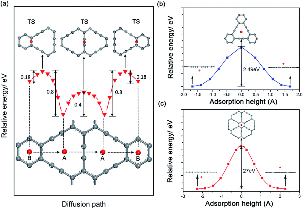 | ||
| Fig. 4 Schematic drawings of diffusion paths (bottom panel) and corresponding energy curves (middle panel) as a function of adsorption sites of Na on GY monolayers, and the corresponding transition states (TS) (top panel) are also demonstrated in (a). Energy curves for Na across the large triangle (b) and the small hexagon (c) of GY monolayers as a function of adsorption height. The energies of equilibrium adsorption configurations are all set to zero. | ||
The calculated energy curves (Fig. 4a) show that the transition state for diffusion path B to A is located on the top of midpoint of the C(sp2)–C(sp2) bond between two adjacent hollows of large triangle and small hexagon. To verify the accuracy of TS prediction using the LST/QST method, we have also calculated other reaction paths by means of starting from the TS and moving down toward the minima along both reactant and product directions. As expected, no energy minima was found on those paths other than the reactant and product. Na migration along the B to A direction has a small activation energy barrier of 0.18 eV. However, when Na diffuse in the reverse direction (A to B), this process responds to a relatively high energy barrier of about 0.8 eV, due to the energetic favorability for the A site over B site. The energy barrier for Na hoping between two neighbouring A sites was found to be 0.4 eV, lower than that in A to B diffusion path. This responds to the transition state located on the top of midpoint of the C(sp)C(sp) triple bond between two adjacent large triangle hollows. Given the energetic stability and kinetics of Na-GY system, the in-plane Na migration on GY is mainly dominated by the A to A hoping path with a mezzo energy barrier of about 0.4 eV, which is superior to that case of Li diffusion on GY with higher energy barriers of 0.53–0.57 eV.41
The rest of two out-plane diffusion paths for GY were also explored, in which Na ions migrate across the hollows from one side of a GY layer to another side along the direction perpendicular to the GY plane. To improve the computational efficiency without losing accuracy, in our calculations of energy profiles for Na out-plane diffusion, these carbon atoms nearest and second nearest to Na ions were allowed to move while the remaining carbon atoms were all kept fixed. Fig. 4b and c show the energy profiles of two typical out-plane diffusion paths. The energy barrier for Na diffusion through a small carbon hexagon is as high as 27 eV. Such an extremely high energy barrier indicates that the out-plane diffusion for Na across a small carbon hexagon is strictly prohibited both in energetics and kinetics under normal working conditions. More interestingly, our calculated results reveal that Na can easily migrate through the large carbon triangle by overcoming a relatively larger energy barrier of 2.49 eV, much less than that Na diffusing through the small carbon hexagon of graphite, GY and graphene. Therefore, we can conclude that the large hollows resulted from the special sp2- and sp-hybridized carbon atoms in GY accelerate not only the Na adsorption but also the out-plane Na migration.
3.3 Na diffusion in GDY
For GDY, in view of the stable adsorption sites, five main diffusion paths were investigated, divided into four in-plane diffusion paths and one out-plane diffusion path, such as B to C, C to A, A to A, C(1) to C(1) and C(1) to C(2), as depicted in Fig. 5a. Although C is not the stable adsorption sites for one Na atom, a unique stable Na occupation pattern on C sites can occur by three symmetric corners of the triangular-like hollows occupied with three Na atoms. Therefore, an important out-plane diffusion path C(1) to C(2) through the large carbon triangle has been also studied.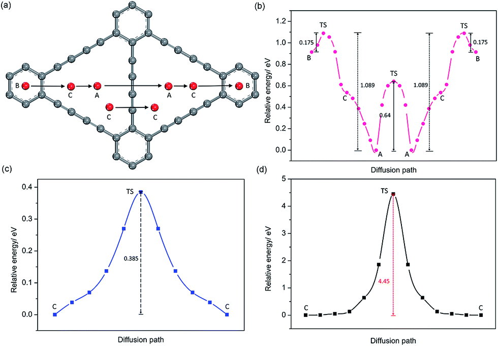 | ||
| Fig. 5 Schematic plots of diffusion paths (a) and corresponding energy curves as a function of adsorption sites of Na on GDY monolayers, and the corresponding transition states (TS). Energy curves (b) and (c) for Na diffusion between two adjacent adsorption sites in the GDY plane, (d) Na diffusion out the plane across the large triangle of GDY monolayers. Here, the minimum energies are all set to zero. | ||
Viewed from the calculated energy profiles of Na diffusion on the GDY plane (Fig. 5b), Na migration along the B to C direction has a small energy barrier of 0.175 eV, close to that case of B to A diffusion path with an energy barrier of 0.18 eV on the GY plane. The corresponding transition state is located above the C(sp2)–C(sp2) bond. While the energy for a Na diffusion in the C to A path is monotonous, consistent with that electrostatic potential plot (Fig. 3d) and above conclusion of one Na preferentially adsorbing on the A site. Interestingly, the energy barrier for Na diffusion in the opposite direction (A to C to B) responds to a relatively high value of 1.089 eV, due to the energetic favorability for the A site over B site. There are two possible hoping patterns for Na migration between the adjacent triangular-like hollows of the GDY, A to A and C to C, which responds to the energy barrier of 0.64 and 0.39 eV (Fig. 5c), respectively. For the out-plane Na diffusion, it has a relatively higher energy barrier of 4.5 eV, indicating that when all the corner of triangular-like hollows occupied by Na ions, Na diffusion through the large hollows from one side to another side of GDY layer is energetically prohibited. But it doesn't hide away the excellent performance of Na diffusion in the plane of GDY. Given the energetic stability and kinetics of Na-GDY system, the in-plane Na migration on GDY is mainly dominated by the A to A and C to C hoping paths with mezzo energy barriers of 0.39–0.64 eV, close to that case of Li diffusion in GDY with energy barriers of 0.35–0.52 eV,37 0.1–0.84 eV.40
4. Conclusions
Energetics and dynamics properties of sodium on the graphyne and graphdiyne have been investigated by the first-principles methods. Calculations indicate that the unique atomic hollow structure of graphyne and graphdiyne resulted from the special sp- and sp2-hybridized carbon atoms accelerates not only the Na storage capacity but also the Na diffusion. Similar to the case of lithium storage in GY and GDY to form the ceiling compounds of LiC4 and LiC3, the stable configuration for maximum sodium storage capacity of GY and GDY also responds to NaC4 and NaC3, respectively, which far exceed that case of Na inserting into graphite to form stage-II ceiling compound NaC12 and is also superior to that case of Li inserting into graphite to form LiC6. Two-dimensional fast Na diffusion (in-plane) in the Na-GY and Na-GDY system can be implemented by overcoming smaller energy barrier of about 0.4 eV. The advantages of Na storage capacity and Na diffusion ability make graphyne and graphdiyne promising candidates for the anode material in sodium-ion battery application.Acknowledgements
We sincerely acknowledge the High Performance Computing Center of CSU, China. This work was financially supported by the National Science and Technology Support Project of China (No. 2012BAE08B02) and National Natural Science Foundation of China (No. 51264011).References
- L. Wu, W. H. Lee and J. Zhang, Mater. Today, 2014, 1, 82–93 CrossRef.
- H. Yu and H. Zhou, J. Phys. Chem. Lett., 2013, 4, 1268–1280 CrossRef CAS PubMed.
- S. P. Ong, V. L. Chevrier and G. Ceder, Phys. Rev. B: Condens. Matter Mater. Phys., 2011, 83, 075112 CrossRef.
- C. Ouyang, S. Shi, Z. Wang, X. Huang and L. Chen, Phys. Rev. B: Condens. Matter Mater. Phys., 2004, 69, 104303 CrossRef.
- J. Jiang, C. Ouyang, H. Li, Z. Wang, X. Huang and L. Chen, Solid State Commun., 2007, 143, 144–148 CrossRef CAS.
- H. Pan, Y.-S. Hu and L. Chen, Energy Environ. Sci., 2013, 6, 2338 CAS.
- Z. Jian, L. Zhao, H. Pan, Y.-S. Hu, H. Li, W. Chen and L. Chen, Electrochem. Commun., 2012, 14, 86–89 CrossRef CAS.
- X. Xiang, K. Zhang and J. Chen, Adv. Mater., 2015, 27, 5343–5364 CrossRef CAS PubMed.
- W. Song, X. Ji, Z. Wu, Y. Zhu, Y. Yang, J. Chen, M. Jing, F. Li and C. E. Banks, J. Mater. Chem. A, 2014, 2, 5358 CAS.
- R. B. Lamuel David and G. Singh, ACS Nano, 2014, 8, 1759–1770 CrossRef PubMed.
- H. W. Jia Ding, Z. Li, A. Kohandehghan, K. Cui, Z. Xu, B. Zahiri, X. Tan, E. Memarzadeh Lotfabad, B. C. Olsen and D. Mitlin, ACS Nano, 2013, 7, 11004–11015 CrossRef PubMed.
- Y. Cao, L. Xiao, M. L. Sushko, W. Wang, B. Schwenzer, J. Xiao, Z. Nie, L. V. Saraf, Z. Yang and J. Liu, Nano Lett., 2012, 12, 3783–3787 CrossRef CAS PubMed.
- L. Zhao, H.-L. Pan, Y.-S. Hu, H. Li and L.-Q. Chen, Chin. Phys. B, 2012, 21, 028201 CrossRef.
- Y. Sun, L. Zhao, H. Pan, X. Lu, L. Gu, Y. S. Hu, H. Li, M. Armand, Y. Ikuhara, L. Chen and X. Huang, Nat. Commun., 2013, 4, 1870 CrossRef PubMed.
- H. Xiong, M. D. Slater, M. Balasubramanian, C. S. Johnson and T. Rajh, J. Phys. Chem. Lett., 2011, 2, 2560–2565 CrossRef CAS.
- P. Senguttuvan, G. Rousse, V. Seznec, J.-M. Tarascon and M. R. Palacín, Chem. Mater., 2011, 23, 4109–4111 CrossRef CAS.
- A. Rudola, K. Saravanan, C. W. Mason and P. Balaya, J. Mater. Chem. A, 2013, 1, 2653 CAS.
- X. H. Yujie Zhu, Y. Xu, Y. Liu, S. Zheng, K. Xu, L. Hu and C. Wang, ACS Nano, 2013, 7, 6378–6386 CrossRef PubMed.
- Y. X. Yihang Liu, Y. Zhu, J. N. Culver, C. A. Lundgren, K. Xu and C. Wang, ACS Nano, 2013, 7, 3627–3634 CrossRef PubMed.
- M. K. Datta, R. Epur, P. Saha, K. Kadakia, S. K. Park and P. N. Kumta, J. Power Sources, 2013, 225, 316–322 CrossRef CAS.
- Y. Okamoto, J. Phys. Chem. C, 2014, 118, 16–19 CAS.
- H. I. M. Yamamoto, Tanso, 2004, 212, 81–90 CrossRef.
- C. J. P. Gábor Csányi, B. D. Simons and R. J. Needs, Phys. Rev. B: Condens. Matter Mater. Phys., 2007, 75, 085432 CrossRef.
- G. Q. L. Z. H. Zhu, Langmuir, 2004, 20, 10751–10755 CrossRef PubMed.
- H. N. Kunihiro Nobuhara, M. Nose, S. Nakanishi and H. Iba, J. Power Sources, 2013, 243, 585–587 CrossRef.
- P. Ge and M. Fouletier, Solid State Ionics, 1988, 28, 1172–1175 CrossRef.
- M. M. Doeff, Y. Ma, S. J. Visco and L. C. De Jonghe, J. Electrochem. Soc., 1993, 140, L169–L170 CrossRef CAS.
- R. Alcántara, J. M. Jiménez-Mateos, P. Lavela and J. L. Tirado, Electrochem. Commun, 2001, 3, 639–642 CrossRef.
- S. Wenzel, T. Hara, J. Janek and P. Adelhelm, Energy Environ. Sci., 2011, 4, 3342 CAS.
- Y. L. Nailiang Yang, H. Wen, Z. Tang, H. Zhao, Y. Li and D. Wang, ACS Nano, 2013, 7, 1504–1512 CrossRef PubMed.
- K. F. Tang, L. White, R. J. Yu, L. Titirici, M.-M. Antonietti and M. Maier, Adv. Energy Mater., 2012, 2, 873–877 CrossRef CAS.
- M. M. Haley, S. C. Brand and J. J. Pak, Angew. Chem., 1997, 36, 836–838 CAS.
- Y. Li, L. Xu, H. Liu and Y. Li, Chem. Soc. Rev., 2014, 43, 2572–2586 RSC.
- A. L. Ivanovskii, Prog. Solid State Chem., 2013, 41, 1–19 CrossRef CAS.
- B. Jang, J. Koo, M. Park, H. Lee, J. Nam, Y. Kwon and H. Lee, Appl. Phys. Lett., 2013, 103, 263904 CrossRef.
- S. Chandra Shekar and R. S. Swathi, J. Phys. Chem. A, 2013, 117, 8632–8641 CrossRef CAS PubMed.
- H. Zhang, Y. Xia, H. Bu, X. Wang, M. Zhang, Y. Luo and M. Zhao, J. Appl. Phys., 2013, 113, 044309 CrossRef.
- Y. Guo, K. Jiang, B. Xu, Y. Xia, J. Yin and Z. Liu, J. Phys. Chem. C, 2012, 116, 13837–13841 CAS.
- H. J. Hwang, J. Koo, M. Park, N. Park, Y. Kwon and H. Lee, J. Phys. Chem. C, 2013, 117, 6919–6923 CAS.
- C. Sun and D. J. Searles, J. Phys. Chem. C, 2012, 116, 26222–26226 CAS.
- H. Zhang, M. Zhao, X. He, Z. Wang, X. Zhang and X. Liu, J. Phys. Chem. C, 2011, 115, 8845–8850 CAS.
- C. Huang, S. Zhang, H. Liu, Y. Li, G. Cui and Y. Li, Nano Energy, 2015, 11, 481–489 CrossRef CAS.
- M. M. I. Sascha Thinius, P. Heitjans and T. Bredow, J. Phys. Chem. C, 2014, 118, 2273–2280 Search PubMed.
- C. D. F. D. P. Di Vincenzo and J. E. Fischer, Phys. Rev. B: Condens. Matter Mater. Phys., 1984, 29, 1115 CrossRef.
- W. W. C. Hartwigsen and E. Spohr, Phys. Rev. B: Condens. Matter Mater. Phys., 1997, 55, 4953–4959 CrossRef.
- P. E. N. K. R. Kganyago and C. R. A. Catlow, Solid State Ionics, 2003, 159, 21–23 CrossRef.
- S. Zhang, H. Liu, C. Huang, G. Cui and Y. Li, Chem. Commun., 2015, 51, 1834–1837 RSC.
- J. K. Ali Alavi, M. Parrinello and D. Frenkel, Phys. Rev. Lett., 1994, 73, 2599 CrossRef PubMed.
- L. J. S. W. Kohn, Phys. Rev., 1965, 140, 1133 CrossRef.
- W. K. P. Hohenberg, Phys. Rev., 1964, 136, 864 CrossRef.
- J. P. P. Ramalho, J. R. B. Gomes and F. Illas, RSC Adv., 2013, 3, 13085 RSC.
- K. B. J. P. Perdew and M. Ernzerhof, Phys. Rev. Lett., 1996, 77, 3865 CrossRef PubMed.
- S. Grimme, J. Antony, S. Ehrlich and H. Krieg, J. Chem. Phys, 2010, 132, 154104 CrossRef PubMed.
- A. R. J. P. Perdew and G. I. Csonka, Phys. Rev. Lett., 2008, 100, 136406 CrossRef PubMed.
- R. C. Kari Laasonen, C. Lee and D. Vanderbilt, Phys. Rev. B: Condens. Matter Mater. Phys., 1991, 43, 6796 CrossRef.
- J. D. P. H. J. Monkhorst, Phys. Rev. B: Solid State, 1976, 13, 5188 CrossRef.
- Y. Li, B. Huang, X. Cheng and Y. Zhang, J. Electrochem. Soc., 2015, 162, A787–A792 CrossRef CAS.
- A. W. Y. Imai, J. Alloys Compd., 2007, 439, 258 CrossRef.
- N. Govind, M. Petersen, G. Fitzgerald, D. King-Smith and J. Andzelm, Comput. Mater. Sci., 2003, 28, 250–258 CrossRef CAS.
Footnote |
| † Electronic supplementary information (ESI) available. See DOI: 10.1039/c6ra01870j |
| This journal is © The Royal Society of Chemistry 2016 |