DOI:
10.1039/C6RA01581F
(Paper)
RSC Adv., 2016,
6, 27871-27878
Preparation of well-defined fibrous hydrogels via electrospinning and in situ “click chemistry”†
Received
19th January 2016
, Accepted 29th February 2016
First published on 3rd March 2016
Abstract
In this work, well-defined PEG-based fibrous hydrogels (FH's) were successfully prepared via electrospinning and in situ copper(I)-catalyzed azide–alkyne cycloaddition (CuAAC) reaction. Initially, the linear functional PEG derivatives with pendant alkynyl groups (PEGn(C
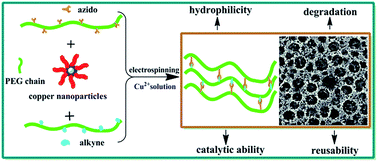
CH))m and with azido moieties (PEGn(N3))m were synthesized via epoxide-amine chain-extension reaction between poly(ethylene glycol) diglycidyl ether (PEGDGE) and propargylamine/1-azido-3-aminopropane. Subsequently, the PEG-based FHs were fabricated from the blends of poly(ethylene oxide) (PEO) and the functional PEG derivatives via electrospinning and in situ CuAAC reaction using the encapsulated copper nanoparticles as the catalyst. The blends of PEO and the functional PEG derivatives were also utilized to prepare the microscopic hydrogels (MH's). The properties of the FH's and MH's were investigated by scanning electron microscopy (SEM) observation, swelling ratios, differential scanning calorimetry (DSC) and in vitro degradation. The copper nanoparticles-encapsulated FH's and MH's were further used to catalyze the CuAAC reaction in a small molecule model. The reusability of the FH's for the CuAAC reaction was also studied.
1. Introduction
Fibrous polymeric structures have attracted much attention due to their high specific surface area and superior mechanical performance.1–4 Polymeric fibers have wide applications in biomedical fields,5–8 chemical and biological sensors,9–12 catalyst supports,13–16 separation,17,18 energy conversion and storage,19 electronic devices20 and so on. Various fabrication methods for the polymeric nanofibers, including self-assembly,21–24 electrospinning25,26 and phase separation1 have been developed. Among them, electrospinning is a simple and low-cost technique method for the preparation of the continuous fibers with different diameters ranging from nanometers to micrometers.27,28 To improve the stability and mechanical properties of electrospun fibers, the chemical cross-linking procedures using external reagents or stimuli (photo and heat) have been employed.29–34 For example, Schiffman et al. electrospun various grades of chitosan and cross-linked them using glutaraldehyde vapor or a Schiff base.35 Huerta-Angeles et al. functionalized hyaluronic acid with (hetoro)-aryl and aliphatic acrylic moieties and used UV irradiation to cross-link the as-fabricated nanofibers.36
“Click chemistry”, particularly copper(I)-catalyzed azide–alkyne cycloaddition (CuAAC),37 is a highly efficient tool used for the preparation and modification of polymeric materials, due to its versatility, mild reaction conditions and high yields.38 CuAAC reaction has been utilized to introduce fluorescein, saccharides, peptide and thermo-responsive polymer onto the electrospun fibers.39–42 However, the utilization of CuAAC reaction to cross-link the electrospun fibers has not been explored. Therefore, a cross-linking system based on the rapid and efficient CuAAC reaction is very promising to create cross-linkers within the electrospun fibers. The CuAAC reaction begins with the coordination of the alkyne moieties to the CuI species, resulting in the reactive π-alkyne–CuI intermediate.43 CuI species can be generated from a CuII salt (usually CuSO4) together with a reducing agent (usually sodium L-ascorbate), a CuI compound (usually CuBr) together with a base or amine ligand, or a metallic Cu0 (nanoparticles, wires, powders and turnings) together with a comproportionation reaction.44–48 The addition of CuI species into the azido- and alkynyl-containing electrospun solution can trigger the CuAAC reaction immediately and result in a non-electrospinnable cross-linking polymeric network. Thus, a CuII salt or metallic Cu0 pre-catalyst is desired to mix with the electrospun solution, prior to the electrospinning process. In comparison to other sources of metallic Cu0, only copper nanoparticles can mix well with the electrospun solution. In comparison to the freely-movable CuII salt, copper nanoparticles can be encapsulated inside the electrospun fibers, acting as a catalyst for the subsequent catalytic reactions.
Herein, azido- and alkynyl-containing poly(ethylene glycol) (PEG) were prepared by epoxide-amine chain-extension reaction between diglycidyl PEG and 1-azido-3-aminopropane/propargylamine. Copper nanoparticles were prepared by one-step chemical method using sodium L-ascorbate as the reducing agent and polyvinylpyrrolidone (PVP) as the stabilizer under microwave irradiation.49 After mixing poly(ethylene oxide) (PEO) with azido- and alkynyl-containing PEG and copper nanoparticles, the solution was electrospun into the copper sulfate aqueous solution, resulting in the fibrous hydrogels (FH's). The macroscopic hydrogels (MH's) with the same components as the FH's were also prepared. The physical properties of FH's and MH's were characterized and compared. The catalytic performance of the copper nanoparticles encapsulated within the FH's and MH's for CuAAC reaction was evaluated by a small molecule model.
2. Experimental section
2.1 Materials
Sodium azide (NaN3, 99%), 3-bromopropylamine hydrobromide, sodium L-ascorbate, ethylene glycol, CuSO4·5H2O, poly(ethylene oxide) (PEO, Mn = 5.0 × 10⁵), sodium hydride (NaH, 60%) and ammonium chloride (NH4Cl) were all purchased from Shanghai Chemical Reagent Plant. Poly(ethylene glycol)diglycidyl ether (PEGDGE, Mn = 500), polyvinylpyrrolidone (PVP, PVP1(Mn=58000), PVP2(Mn=24000), PVP3(Mn=8000)), epichlorohydrin (99%), benzyl chloride and propargyl alcohol were purchased from Aldrich Chemical Co. Tetrahydrofuran (THF) was dried by refluxing over sodium and distilled directly into reaction flasks. Propargylamine (J&K Scientific, 80%) was distilled before use. 1-Azido-3-aminopropane, azido-containing PEG ((PEG11(N3))19), alkynyl-containing PEG ((PEG11(C
CH))28) and benzyl azide were prepared according to the methods reported in the literatures.50–52 The detailed procedures were described in ESI.†
2.2 Preparation of copper nanoparticles
PVP, sodium L-ascorbate, and CuSO4·5H2O were dissolved in ethylene glycol to form 0.01 M, 0.25 M and 0.1 M solutions, respectively. Then, 5 mL of PVP solution was added into 25 mL of copper sulfate solution. The mixture solution was stirred for 30 min, followed by the addition of 25 mL of sodium L-ascorbate solution. After stirring for another 15 min, the precursor was put into a microwave oven (700 W, Midea Microwaves Oven Corp, Guangzhou, China) and reacted for 2 min in high-medium power. The color of the mixture solution turned into red. The copper nanoparticles were finally obtained. The copper nanoparticles prepared from PVP1, PVP2 and PVP3 are referred to copper nanoparticles (A), (B) and (C), respectively.
2.3 Synthesis of PEG-based macroscopic hydrogels (MH's) via CuAAC using copper nanoparticles as the catalysts
(PEG11(N3))19 (0.35 g, 0.037 mmol), (PEG11(C
CH))28 (0.37 g, 0.025 mmol), 1.43 mL of 25 wt% PEO ethanol/water (v/v = 2
:
3) mixture solution and as-prepared copper nanoparticles (A) solution (10 μL) was mixed. After stirring the mixture for 1 h, 5 mL of CuSO4 aqueous solution (1.33 M) was added into the reaction mixture at 50 °C. The MH's were also prepared with other weight ratios of PEO to the functional PEG derivatives. The resulting MH's with the PEO to the functional PEG derivatives weight ratios of 0.1, 0.3, 0.5, 0.7 and 0.9 were denoted as MH0.1, MH0.3, MH0.5, MH0.7 and MH0.9, respectively.
2.4 Synthesis of PEG-based fibrous hydrogels (FH's) via electrospinning and in situ CuAAC using copper nanoparticles (A) as the catalysts
The electrospinning apparatus was equipped with a high-voltage power source (Dalian Taisiman), a syringe pump (SLGO CP-1000), and a syringe with stainless steel needle (diameter = 0.7 mm). The gel precursors used for the preparation of the MH's were mixed without the addition of CuSO4 aqueous solution, and stirred for 1 h. After that, the gel precursors were transferred into the syringe and spun at a voltage of 18 kV with a constant feeding rate of 0.08 mL h−1. The solution was electrospun into CuSO4 aqueous solution (1.33 M) at 50 °C. The distance between the needle tip to liquid level of CuSO4 aqueous solution was set at 15 cm. Similar to the MH's, a variety of FH's with different weight ratios of PEO to the functional PEG derivatives were also prepared. The resulting FH's with PEO to the functional PEG derivatives weight ratios of 0.1, 0.3, 0.5, 0.7 and 0.9 were denoted as FH0.1, FH0.3, FH0.5, FH0.7 and FH0.9, respectively.
2.5 Swelling behavior
The MH's and FH's with different weight ratios of PEO to the functional PEG derivatives were completely dried until constant weights. The MH's and FH's were then immersed into deionized water, and weighted at a predetermined time after removing the adhered water on the outer surfaces. The degree of swelling (DS) was calculated using the following equation: |
DS = (Wwet − Wdry)/Wdry × 100%
| (1) |
where Wwet and Wdry are the weights of the wet and dry samples, respectively.
2.6 In vitro degradation
The in vitro degradation tests of PEG-based MH's and FH's was carried out at 37 °C by immersing in phosphate buffered saline (PBS, 10 mM, pH = 7.4). The samples were periodically taken out from the PBS solution, and weighted after removing the adhered water on the outer surfaces. The percentage of the mass loss was calculated from equation: |
Mass loss (%) = (m0 − mi)/m0 × 100%
| (2) |
where m0 is the initial weight of dry MH's or FH's and mi is the weight of MH's or FH's after degradation at a predetermined time.
2.7 CuAAC catalyzed by copper nanoparticles-encapsulated FH and MH
Benzyl azide (0.53 g, 5.0 mmol) and propargyl alcohol (0.22 g, 5.0 mmol) were mixed in 0.25 mL of methanol. Then, 64.0 mg of FH0.3 and 40.0 μL of 0.01 M CuSO4 methanol solution were added into the reaction mixture. The copper nanoparticles-encapsulated FH0.3 or MH0.3 was utilized to trigger the CuAAC at 50 °C. The reaction yield was monitored by the gas chromatography. The gas chromatography (GC-6890, Labthink Instruments Co. Ltd.) was equipped with a flame ionization detector and the capillary column (SE-54, 50 m in length and 0.32 mm in diameter). The carrier gas was high purity nitrogen, and the operating conditions of GC analysis were as follows: the injector temperature at 553 K, the oven temperature at 543 K, and the detector temperature at 593 K.
2.8 Characterization
The copper nanoparticles were dispersed in absolute ethanol and centrifuged at 8000 rpm for 50 min. The settled particles were repeatedly washed with ethanol and water, and finally dried at 50 °C in a vacuum oven for 3 h. X-ray powder diffraction (XRD) was performed on a D8-Discover diffractometer using nickel-filtered CuKα radiation. The morphology of copper nanoparticles were observed on a transmission electron microscope (TEM, FEI Tecnai G220), operating with an accelerating voltage of 20–200 kV. Chemical structures of the functional PEG derivatives were characterized by FT-IR (Bruker Vector 22), 1H NMR (300 MHz, Bruker) and 13C NMR (400 MHz, Bruker) spectroscopies. Molecular weights of the functional PEG derivatives were measured by gel permeation chromatography (GPC, Waters 1515) using polystyrene molecular weight standards. Morphologies of PEG-based MH's and FH's were observed by a scanning electron microscopy (SEM, Phenom PRO X) at an accelerating voltage of 10 kV after sputter-coating with gold. The thermal property was investigated on a differential scanning calorimetry (DSC, TA Q-2000).
3. Results and discussion
3.1 The preparation of copper nanoparticles
The XRD patterns of copper nanoparticles (A), (B) and (C) synthesized by one-step chemical method are shown in Fig. 1. The XRD patterns of copper nanoparticles (A), (B) and (C) are similar. The characteristic peaks at 2θ = 43.2°, 50.4° and 74.0°, corresponding to (111), (200) and (220) planes of face-centered cubic (FCC) copper, respectively, can be observed. This result confirms the formation of pure copper nanoparticles with negligible oxides or impurity phases.
 |
| Fig. 1 XRD pattern of copper nanoparticles (A), (B) and (C). | |
The structure and morphology of copper nanoparticles (A), (B) and (C) were investigated by TEM images. Fig. 2A–C shows the TEM images of copper nanoparticles (A), (B) and (C). The average diameters of copper nanoparticles (A), (B) and (C) are about 40, 100 and 200 nm, respectively. The average diameters of copper nanoparticles increase gradually with the decrease in the molecular weights of PVP. The possible reason is that the space effect of longer PVP polymer chain could prevent the agglomeration between copper atoms. Furthermore, higher molecular weight PVP exhibits a higher viscosity. Its volume effect reduced imentation velocity of copper atoms due to the displacements of Brownian motion.
 |
| Fig. 2 TEM images of copper nanoparticles (A), (B) and (C). | |
3.2 Synthesis of linear functional PEG derivatives
The synthetic route of azido-containing PEG ((PEG11(N3))19) and alkynyl-containing PEG ((PEG11(C
CH))28) was shown in Scheme 1B. Diglycidyl PEGDGE was chain-extended with 1-azido-3-aminopropane and propargylamine via epoxide-amine reaction, resulting in (PEG11(N3))19 and (PEG11(C
CH))28, respectively. Fig. S2 (ESI†) shows the GPC traces of PEGDGE, (PEG11(N3))19 and (PEG11(C
CH))28. The molecular weights and polydispersity index (PDI) of (PEG11(C
CH))28 and (PEG11(N3))19 are summarized in Table 1. In comparison to the PEGDGE, the number-average molecular weight (Mn) of (PEG11(C
CH))28 increases to 14
600 with a PDI of 1.32, and the Mn of (PEG11(N3))19 increases to 9500 with a PDI of about 1.42.
 |
| Scheme 1 (A) The schematic illustration of the preparation of copper nanoparticles and the fabrication of fibrous hydrogels via electrospinning and in situ CuAAC; (B) the synthesis of azido- and alkynyl-containing PEG. | |
Table 1 Molecular weights of the functional PEG derivatives
PEG derivatives |
Mn (g mol−1) |
Mw (g mol−1) |
PDI |
PEGDGE |
500 |
510 |
1.02 |
(PEG11(C CH))28 |
14 600 |
19 300 |
1.32 |
(PEG11(N3))19 |
9500 |
13 500 |
1.42 |
The chemical structures of (PEG11(C
CH))28 and (PEG11(N3))19 were ascertained by 1H and 13C NMR spectroscopies. Fig. S3 (ESI†) shows the 1H NMR spectra of (PEG11(C
CH))28 and (PEG11(N3))19. The peaks at 2.23 and 3.41 ppm are assigned to the methylidyne protons of alkynyl group and the methylene protons adjacent to the azido group, respectively. The signals at about 2.6 ppm are assigned to the methylene protons groups adjacent to the tertiary nitrogen. Fig. S4 (ESI†) shows the 13C NMR spectra of (PEG11(C
CH))28 and (PEG11(N3))19. The resonance signals at about 73.1 and 48.3 ppm correspond to the methylidyne carbon atoms of alkynyl group and the methylene carbon atoms adjacent to the azido group, respectively. The respective signals of methylene carbon atoms adjacent to the tertiary nitrogen of (PEG11(C
CH))28 and (PEG11(N3))19 occur in the range of 53.5–56.8 and 51.8–56.4 ppm. These results indicate that (PEG11(C
CH))28 with alkynyl groups and (PEG11(N3)19) with azido moieties have been successfully synthesized. The distinctive absorbance peak at about 2135 cm−1 in the FT-IR spectrum of (PEG11(C
CH))28 (Fig. 3B) is attributable to the alkynyl moieties. The distinctive absorbance peak at about 2101 cm−1 in the FT-IR spectrum of (PEG11(N3))19 (Fig. 3C) is belonging to the azido moieties.
 |
| Fig. 3 FT-IR spectra of (A) PEGDGE, (B) (PEG11(C CH))28, (C) (PEG11(N3))19, (D) FH0.3 and (E) MH0.3. | |
3.3 Synthesis of PEG-based MH's and FH's
Attempts to electrospin the functional PEG derivatives in either water or organic solvents are unsuccessful, due to their low molecular weights. The addition of PEO to the functional PEG derivatives can improve their surface tension and viscosity, favoring the following electrospinning. To compare the physical properties between MH's and FH's, PEO was also added into the gel precursors for the preparation of MH's. After mixing the functional PEG derivatives with PEO and copper nanoparticles, the addition of CuSO4 can accelerate the CuAAC reaction to form the cross-linking points rapidly. The gelation of the PEG-based MH's prepared from the PEO to functional PEG derivatives weight ratio of 0.5 is occurred at 4, 5.5 and 7 min, respectively, using copper nanoparticles (A), (B) and (C) as the catalysts. The preparation of PEG-based MH's using copper nanoparticles (A) exhibits the fastest gelation rate, favoring the in situ cross-linking of PEG-based FH's. Thus, copper nanoparticles (A) were utilized for the preparation of PEG-based MH's and the following FH's with different weight ratios of PEO to the functional PEG derivatives.
The gel precursors with the functional PEG derivatives, copper nanoparticles (A) and PEO were spun into CuSO4 aqueous solution. The fast CuAAC initiated by the comproportionation reaction between metallic copper nanoparticles and CuSO4 can cross-link the gel precursors, resulting in the FH's. Fig. 3D and E displays the FT-IR spectra of MH0.3 and FH0.3. The azido groups at about 2101 cm−1 and alkynyl moieties at about 2135 cm−1 are almost indiscernible, suggesting the CuAAC reaction catalyzed by the copper nanoparticles has been successfully taken place in both macroscopic and fibrous forms.
3.4 Physical properties of the PEG-based MH's and FH's
While the blended composites of PEO and the functional PEG derivatives can be electrospun, the contents of PEO in the blends can greatly influence the morphology of FH's and MH's. Fig. 4 shows the SEM images of the PEG-based FH's and MH's fabricated at different weight ratios of PEO to the functional PEG derivatives (0.1, 0.3, 0.5, 0.7 and 0.9) using copper nanoparticles (A) as the catalyst. In the case of FH0.1, the low content of PEO can't prevent the cross-linking between the functional PEG derivatives within different electrospun fibers, resulting in a deeply cross-linked aggregate. As the PEO content increased, the cross-linking between different electrospun fibers is largely inhibited and the unavoidable cross-linking leads to the formation of a porous mat in FH0.3. With the further increase in the PEO contents, well-defined fibrous hydrogels (FH0.5, FH0.7 and FH0.9) are formed. For all the MH's, only bulk materials with irregular pores are observed. The SEM observations suggest that the fibrous hydrogels have been successfully fabricated.
 |
| Fig. 4 SEM images of PEG-based FH's and MH's at different weight ratios of PEO to the functional PEG derivatives using copper nanoparticles (A) as the catalyst. | |
Fig. 5 shows the DSC heating curves of PEO and PEG-based FH's. The melting temperature (Tm) of PEO is 54.6 °C. After blending with the functional PEG derivatives, the melting peak of PEO does not appear. This phenomenon is probably due to the entangled PEO segments are not enough long to crystallize within the functional PEG matrixes. The Tg of FH0.1, FH0.3, FH0.5, FH0.7 and FH0.9 are about −30.01, −31.13, −31.46, −31.76 and −31.81 °C, respectively. The Tg decreases with the increase in the weight ratio of PEO to the functional PEG derivatives. The result is consistent with the fact that the higher cross-linking densities of FH's, the higher Tg of the FH's.
 |
| Fig. 5 Heating curves of DSC measurements of (A) PEO and (B) FH0.1, (C) FH0.3, (D) FH0.5, (E) FH0.7 and (F) FH0.9. | |
Fig. 6 indicates the swelling ratios of FH's and MH's with different weight ratios of PEO to the functional PEG derivatives in deionized water. Both FH's and MH's can absorb water and swell rapidly. In comparison to the MH's, FH's exhibit higher swelling ratios with the same weight ratios of PEO to the functional PEG derivatives. This result indicates that the FH's can contact and adsorb the water molecules more conveniently than MH's. This finding is consistent with the higher surface areas of the FH's observed in the SEM images.
 |
| Fig. 6 Swelling ratios of MH's (a) and FH's (b) with different PEO to the functional PEG derivatives weight ratios of (A) 0.1, (B) 0.3, (C) 0.5, (D) 0.7 and (E) 0.9. | |
3.5 In vitro degradation
The degradation study of PEG-based FH's was carried out in 10 mM PBS (pH = 7.4) at 37 °C. As shown in Fig. 7, all of the FH's degrade with the increase in the immersion time. After 70 days, the mass losses of the FH0.1, FH0.3, FH0.5, FH0.7 and FH0.9 are 53.35%, 58.79%, 64.17%, 71.82% and 83.99%, respectively. The mass losses of these FH's increase with the increase in the PEO contents. The higher PEO contents in the FH's correspond to the lower contents of the functional PEG derivatives as well as the less cross-linking points. The lower cross-linking densities in the FH's with the higher PEO contents result in poor stability, upon immersion in the medium. The degradation of MH's and FH's in PBS was also compared. FH0.1 exhibits a faster degradation than MH0.1 with the same weight ratio of PEO to the functional PEG derivatives. The faster degradation of FH0.1 may be arising from its higher surface area.
 |
| Fig. 7 Mass loss profiles of (A) MH0.1, (B) FH0.1, (C) FH0.3, (D) FH0.5, (E) FH0.7 and (F) FH0.9 after immersion in PBS. | |
3.6 CuAAC reaction catalyzed by copper nanoparticles-encapsulated FH and MH
The copper nanoparticles were encapsulated in the FH's after electrospinning and in situ CuAAC reaction. The as-formed FH's can be further utilized as solid-state catalysts to catalyze the azide–alkyne cycloaddition. A model CuAAC reaction between propargyl alcohol and benzyl azide was carried out using FH0.3 as the catalyst in the presence of CuSO4. Fig. S5B (ESI†) shows the 1H NMR spectrum of the product generated in the reaction system. The peak assignments are consistent with 1,2,3-triazole products formed via CuAAC reaction. The yield of the CuAAC reaction catalyzed by copper nanoparticles-encapsulated FH and MH was monitored by GC. As shown in Fig. 8, the yield of 1,2,3-triazole product is around 91% at 10 min using FH0.3 as the catalyst. Since the MH's contain the copper nanoparticles, their catalytic property for CuAAC reaction was also measured. The yield of 1,2,3-triazole ring is about 63% at 10 min using MH0.3 as the catalyst. The FH0.3 has a higher surface area than MH0.3, resulting in a faster catalytic reaction rate. Although the CuAAC reaction catalyzed by MH0.3 is slow, its yield is comparable to that catalyzed by FH0.3 at a prolonged reaction time. At 40 min, the yields of 1,2,3-triazole product can reach about 96% for both reaction systems catalyzed by FH0.3 and MH0.3. The durability of the FH0.3 for the CuAAC reaction was evaluated by employing it in several successive reactions. In the first cycle, the yield of the 1,2,3-triazole product can reach 96%. During the second and third cycles, the yields decrease to 93% and 89%, respectively. Thus, the as-synthesized fibrous hydrogels are designed for solid-state catalysts for CuAAC reaction with a good reusability.
 |
| Fig. 8 The time-dependent yields of 1,2,3-triazole product in the CuAAC reaction catalyzed by the copper nanoparticles-encapsulated FH0.3 and MH0.3. | |
4. Conclusion
FH's were fabricated from the blends of PEO and the functional PEG derivatives via electrospinning and in situ CuAAC reaction using copper nanoparticles as the catalyst. The resulting FH's show well-defined fibrous structures, when the high PEO contents are present in the blends. The FH's exhibit higher surface areas than MH's, as revealed by the swelling ratio and in vitro degradation assays. The FH's with higher surface areas exhibit a faster catalytic efficiency than MH's for CuAAC reaction of benzyl azide and propargyl alcohol. The FH's can also be repeatedly used to catalyze the CuAAC reaction. Thus, the encapsulation of copper nanoparticles in electrospun fibers not only can cross-link the as-formed fibers via in situ CuAAC reaction, but also can be utilized to catalyze the CuAAC reaction. The FH's can be easily separated from the reaction mixture, acting as an excellent catalyst supports.
Acknowledgements
This work was supported by National Natural Science Foundation of China under the Grant 21274020, 21074022, 21304019 and 21504072. This work was also supported by the Key Laboratory of Environmental Medicine Engineering of Ministry of Education (Southeast University).
References
- V. Beachley and X. Wen, Prog. Polym. Sci., 2010, 35, 868–892 CrossRef CAS PubMed.
- K. Yoon, B. S. Hsiao and B. Chu, J. Mater. Chem., 2008, 18, 5326–5334 RSC.
- J. Venugopal and S. Ramakrishna, Appl. Biochem. Biotechnol., 2005, 125, 147–157 CrossRef CAS PubMed.
- K. Jayaraman, M. Kotaki, Y. Zhang, X. Mo and S. Ramakrishna, J. Nanosci. Nanotechnol., 2004, 4, 52–65 CAS.
- T. J. Sill and H. A. von Recum, Biomaterials, 2008, 29, 1989–2006 CrossRef CAS PubMed.
- W. J. Li, C. T. Laurencin, E. J. Caterson, R. S. Tuan and F. K. Ko, J. Biomed. Mater. Res., 2002, 60, 613–621 CrossRef CAS PubMed.
- D. Liang, B. S. Hsiao and B. Chu, Adv. Drug Delivery Rev., 2007, 59, 1392–1412 CrossRef CAS PubMed.
- H. Yoshimoto, Y. M. Shin, H. Terai and J. P. Vacanti, Biomaterials, 2003, 24, 2077–2082 CrossRef CAS PubMed.
- K. Sawicka, P. Gouma and S. Simon, Sens. Actuators, B, 2005, 108, 585–588 CrossRef CAS.
- Z. Wang, Z. Li, T. Jiang, X. Xu and C. Wang, ACS Appl. Mater. Interfaces, 2013, 5, 2013–2021 CAS.
- W. Zheng, X. Lu, W. Wang, Z. Li, H. Zhang, Y. Wang, Z. Wang and C. Wang, Sens. Actuators, B, 2009, 142, 61–65 CrossRef CAS.
- Y. Liao, C. Zhang, Y. Zhang, V. Strong, J. Tang, X.-G. Li, K. Kalantar-zadeh, E. M. V. Hoek, K. L. Wang and R. B. Kaner, Nano Lett., 2011, 11, 954–959 CrossRef CAS PubMed.
- J. Huang, D. Wang, H. Hou and T. You, Adv. Funct. Mater., 2008, 18, 441–448 CrossRef CAS.
- R. Ostermann, D. Li, Y. D. Yin, J. T. McCann and Y. N. Xia, Nano Lett., 2006, 6, 1297–1302 CrossRef CAS PubMed.
- Z. Zhang, C. Shao, Y. Sun, J. Mu, M. Zhang, P. Zhang, Z. Guo, P. Liang, C. Wang and Y. Liu, J. Mater. Chem., 2012, 22, 1387–1395 RSC.
- Z. Zhang, C. Shao, X. Li, C. Wang, M. Zhang and Y. Liu, ACS Appl. Mater. Interfaces, 2010, 2, 2915–2923 CAS.
- R. Gopal, S. Kaur, Z. Ma, C. Chan, S. Ramakrishna and T. Matsuura, J. Membr. Sci., 2006, 281, 581–586 CrossRef CAS.
- Z. W. Ma, M. Kotaki and S. Ramakrishna, J. Membr. Sci., 2005, 265, 115–123 CrossRef CAS.
- S. Cavaliere, S. Subianto, I. Savych, D. J. Jones and J. Roziere, Energy Environ. Sci., 2011, 4, 4761–4785 CAS.
- J. Miao, M. Miyauchi, T. J. Simmons, J. S. Dordick and R. J. Linhardt, J. Nanosci. Nanotechnol., 2010, 10, 5507–5519 CrossRef CAS PubMed.
- B. A. Grzybowski, C. E. Wilmer, J. Kim, K. P. Browne and K. J. M. Bishop, Soft Matter, 2009, 5, 1110–1128 RSC.
- M. G. Han and S. H. Foulger, Small, 2006, 2, 1164–1169 CrossRef CAS PubMed.
- M. Hasegawa and M. Iyoda, Chem. Soc. Rev., 2010, 39, 2420–2427 RSC.
- A. Schenning and E. W. Meijer, Chem. Commun., 2005, 3245–3258 RSC.
- A. Frenot and I. S. Chronakis, Curr. Opin. Colloid Interface Sci., 2003, 8, 64–75 CrossRef CAS.
- X. Lu, C. Wang and Y. Wei, Small, 2009, 5, 2349–2370 CrossRef CAS PubMed.
- A. Greiner and J. H. Wendorff, Angew. Chem., Int. Ed., 2007, 46, 5670–5703 CrossRef CAS PubMed.
- W. E. Teo and S. Ramakrishna, Nanotechnology, 2006, 17, R89–R106 CrossRef CAS PubMed.
- G. Fu, Z. Su, X. Jiang and J. Yin, Polym. Chem., 2014, 5, 2027–2034 RSC.
- M. W. Thielke, E. P. Bruckner, D. L. Wong and P. Theato, Polymer, 2014, 55, 5596–5599 CrossRef CAS.
- C. Tang, C. D. Saquing, J. R. Harding and S. A. Khan, Macromolecules, 2010, 43, 630–637 CrossRef CAS.
- L. Wei-Han and T. Wei-Bor, Biofabrication, 2013, 5, 035008 CrossRef PubMed.
- E. Giebel, J. Getze, T. Röcker and A. Greiner, Macromol. Mater. Eng., 2013, 298, 439–446 CrossRef CAS.
- C. Zhou, Q. Wang and Q. Wu, Carbohydr. Polym., 2012, 87, 1779–1786 CrossRef CAS.
- J. D. Schiffman and C. L. Schauer, Biomacromolecules, 2007, 8, 594–601 CrossRef CAS PubMed.
- G. Huerta-Angeles, M. Brandejsová, K. Knotková, M. Hermannová, M. Moravcová, D. Šmejkalová and V. Velebný, Carbohydr. Polym., 2016, 137, 255–263 CrossRef CAS PubMed.
- J. E. Hein and V. V. Fokin, Chem. Soc. Rev., 2010, 39, 1302–1315 RSC.
- J. A. Johnson, M. G. Finn, J. T. Koberstein and N. J. Turro, Macromol. Rapid Commun., 2008, 29, 1052–1072 CrossRef CAS.
- G. D. Fu, L. Q. Xu, F. Yao, K. Zhang, X. F. Wang, M. F. Zhu and S. Z. Nie, ACS Appl. Mater. Interfaces, 2009, 1, 239–243 CAS.
- A. Lancuski, S. Fort and F. Bossard, ACS Appl. Mater. Interfaces, 2012, 4, 6499–6504 CAS.
- Y.-C. Qian, N. Ren, X.-J. Huang, C. Chen, A.-G. Yu and Z.-K. Xu, Macromol. Chem. Phys., 2013, 214, 1852–1858 CrossRef CAS.
- J. Zheng, G. Hua, J. Yu, F. Lin, M. B. Wade, D. H. Reneker and M. L. Becker, ACS Macro Lett., 2015, 4, 207–213 CrossRef CAS.
- L. Liang and D. Astruc, Coord. Chem. Rev., 2011, 255, 2933–2945 CrossRef CAS.
- Y. Jiang, X. He, W. Zhang, X. Li, N. Guo, Y. Zhao, G. Xu and W. Li, RSC Adv., 2015, 5, 73340–73345 RSC.
- S. B. Salunke, N. S. Babu and C.-T. Chen, Chem. Commun., 2011, 47, 10440–10442 RSC.
- F. Alonso, Y. Moglie and G. Radivoy, Acc. Chem. Res., 2015, 48, 2516–2528 CrossRef CAS PubMed.
- L. D. Pachón, J. H. van Maarseveen and G. Rothenberg, Adv. Synth. Catal., 2005, 347, 811–815 CrossRef.
- F. Himo, T. Lovell, R. Hilgraf, V. V. Rostovtsev, L. Noodleman, K. B. Sharpless and V. V. Fokin, J. Am. Chem. Soc., 2005, 127, 210–216 CrossRef CAS PubMed.
- W. Yihai, C. Penglei and L. Minghua, Nanotechnology, 2006, 17, 6000 CrossRef.
- A. Saha, S. De, M. C. Stuparu and A. Khan, J. Am. Chem. Soc., 2012, 134, 17291–17297 CrossRef CAS PubMed.
- S. G. Alvarez and M. T. Alvarez, Synthesis, 1997, 413–414 CrossRef CAS.
- R. S. Varma and K. P. Naicker, Tetrahedron Lett., 1998, 39, 2915–2918 CrossRef CAS.
Footnote |
† Electronic supplementary information (ESI) available. See DOI: 10.1039/c6ra01581f |
|
This journal is © The Royal Society of Chemistry 2016 |
Click here to see how this site uses Cookies. View our privacy policy here.