A new concept for electroless nickel plating: aluminium as reducing agent

Xingkai Zhang and Junyan Zhang*
State Key Laboratory of Solid Lubrication, Lanzhou Institute of Chemical Physics, Chinese Academy of Sciences, Lanzhou 730000, China. E-mail: zhangjunyan@licp.cas.cn; Tel: +86 931 4968295

Received 17th January 2016 , Accepted 10th March 2016

First published on 11th March 2016


Abstract

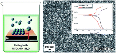
A facile electroless plating strategy to obtain nickel coatings on copper substrates was designed to simplify the plating baths and procedure. The plating baths contained only nickel sulfate and ammonia. The aluminium connected to the copper substrates served as the electron source for nickel deposition. The nickel coatings obtained via this approach were tested and proved to possess excellent anticorrosion behavior.

1 Introduction

Copper is widely used in electricity systems, electronics, machinery and decoration fields for its promising electrical conductivity, thermal conductivity, mechanical workability and fine appearance.1 However, copper is prone to oxidation and corrosion in humid environments,2 which generally results in the premature failure of copper products.3 Various methods have been developed to inhibit the oxidation and corrosion of copper, and one of the effective methods is surface coating treatment.4,5 As a well-known method for preparing coatings or films of metals and their alloys, electroless plating is a convenient and effective technique to improve the corrosion resistance of copper while eliminating the need for complicated equipment and dangerous power sources.6 The utilization of electroless nickel plating has grown steadily during the last decade because of the promising corrosion and wear resistance of nickel based coatings.7 However, electroless nickel plating has its problems, which emerge from the complexity of the plating bath. A traditional electroless nickel plating bath8 is complex and usually contains complexing agents, nickel salts, reducing agents, buffering agents, stabilizers, etc. Reducing agents, including NaH2PO2,9 KBH4[thin space (1/6-em)]10 and N2H4·H2O,11 have been used to prepare nickel coatings, and these costly and hazardous reducing agents usually lead to decreased stability of the plating baths. In addition, nickel cannot be electrolessly deposited on copper automatically because copper is inert to the hypophosphite oxidation reaction;12 therefore, complicated sensitization or activation steps13 are generally required.

Aluminium or iron wire can also be used to initiate electroless nickel plating on copper and its alloys by bringing them in contact with the substrates;14–16 in addition, electroless Fe–P plating was first achieved by coupling copper substrates with aluminium foil.17 Using the same technique, by introducing other elements, multicomponent iron alloys were also prepared;18,19 the plating rate of iron alloys without coupled aluminium is too slow to be observed.20

As mentioned above, aluminium is used to initiate or promote the electroless plating process; the reason is that aluminium can serve as the electron source, but aluminium is rarely used as a reducing agent to prepare electroless nickel coatings directly. Therefore, inspired by the above phenomena, we designed a facile electroless plating strategy to prepare nickel coatings on copper substrates in this paper. Aluminium was used instead of traditional and costly reducing agents in order to simplify the electroless nickel plating bath and process. The used plating bath only contained nickel sulphate and ammonia, and the plating process was to immerse copper substrates connected with aluminium into the above plating bath directly at room temperature. The plating bath was stable and could be used repeatedly, as it contained no reducing agent. The kinetics of the electroless nickel plating process was studied by electrochemical methods. The obtained nickel coatings were tested and proved to have excellent corrosion resistance.

2 Experimental

The copper substrates (99.9% purity) were etched with 5 wt% HCl solution for 30 s; they were then connected with aluminium foils and immersed into the plating bath without any sensitization or activation steps. The plating bath contained NiSO4·6H2O (20 g L−1) and ammonia (25 wt%, 500 mL L−1). After plating for 30 min at 20 °C, the samples were rinsed with de-ionized water and ethanol and then dried in a nitrogen stream. The traditional electroless nickel coating was prepared from a typical bath containing NiSO4·6H2O (30 g L−1), NaH2PO2·H2O (10 g L−1), C6H5O7(NH4)3 (65 g L−1), and NH4Cl (50 g L−1). Operating conditions were pH 9 (adjusted with 5 M NaOH solution), temperature 85 °C.7 The pure aluminium foil was connected with the copper substrates for several minutes to induce the electroless nickel plating; otherwise, the nickel coating could not be obtained.

The surface and cross-sectional morphology and structure of the coating were characterized by scanning electron microscopy (JSM 6701F and JSM 5600LV, JEOL) with energy dispersive X-ray spectroscopy and a glancing angle X-ray diffractometer (D/MAX2500, Rigaku). Electrochemical measurements were performed using an electrochemical analyser (μ Autolab III, Metrohm) with platinum as the counter electrode and Ag/AgCl electrode (saturated KCl) as the reference electrode. The potentials of copper, aluminium and copper connected with aluminium foil were measured in the plating bath and NiSO4·6H2O solution (20 g L−1). To simulate partial cathodic or anodic reactions, linear sweep voltammetry experiments of copper and aluminium in NiSO4 solution or plating bath were carried out. To investigate the corrosion behaviour of the nickel coatings, potentiodynamic polarization tests were performed in 3.5 wt% NaCl solution. The open circuit potential measurements were maintained up to 60 min. The potentiodynamic polarization tests were carried out at a scan rate of 2 mV s−1.

3 Results and discussion

After the coating process, the copper substrates were covered by uniform coatings with a silver-white appearance. The coating consisted of granules with irregular shapes, ranging in size under 100 nm, as shown in Fig. 1a and b. The granules were tightly packed to ensure a compacted structure. The EDX analysis result confirmed that the coating was composed of pure nickel (insert image in Fig. 1a). The XRD result indicated the coating showed typical crystallized peaks of fcc Ni at 2θ = 44.6°, 52.1° and 76.2° (inset image in Fig. 1b), which corroborated the result of the EDX analysis. Although the cross-sectional morphology of the sample is given in Fig. 1c, it was difficult to distinguish the coating and substrate under the electron microscope, as nickel and copper are adjacent elements in the periodic table. Therefore, EDX 2-D elemental mappings of copper and nickel were performed across cross-sections of the nickel coated samples (Fig. 1d). It can be clearly observed that a thin layer of nickel, which was compact, continuous and uniform, exists at the surface of the copper substrate. The average thickness of the nickel coating was about 1.0 μm.
image file: c6ra01435f-f1.tif
Fig. 1 (a) and (b): Surface morphology of the nickel coating obtained from the reducing agent-free bath; cross-sectional morphology (c) and corresponding elemental mapping (d) of the sample. The inset images in (a) and (b) are the EDX spectrum and XRD pattern, respectively.

Fig. 2a and b show the surface morphology of the coatings deposited from the traditional plating bath. The coating also showed a compact structure; however, the size of the nodules was estimated to be about 100 to 200 nm. Compared with the nickel coatings prepared from the reducing agent-free bath, the traditional nickel coatings consisted of nodules with larger sizes and showed clearer nodule boundaries. Because sodium hypophosphite was used as the reducing agent, the obtained nickel coatings contained 14.2 wt% phosphorus, as verified by the inset image in Fig. 2a. The cross-sectional morphology and corresponding elemental distribution mapping of the traditional nickel coating were given in Fig. 2c and d, from which a uniform and compact layer formed on the copper substrate can be observed. Elemental nickel and phosphorus were uniformly distributed throughout the coating and the coating thickness increased to about 2.1 μm as a result of using a reducing agent.


image file: c6ra01435f-f2.tif
Fig. 2 (a) and (b): Surface morphology of the traditional nickel coating; cross-sectional morphology (c) and corresponding elemental mapping (d) of the sample. The inset image in (a) is the EDX spectrum.

Nickel coatings were successfully prepared on copper substrates from a simple plating bath. To explore the possible mechanism of the nickel plating process, a contrast experiment was performed. No coatings were obtained on the copper surface when copper substrates connected with aluminium were immersed into NiSO4·6H2O solution (20 g L−1) for 30 min. The OCP-t technique was used to understand the reason. As shown in Fig. 3a, the potential of the copper substrate in the plating bath was −0.554 V, and it shifted negatively to about −1.152 V as the copper substrate was connected with aluminium foil. From Fig. 3b, the above phenomenon was more obvious. It was observed that the potential of the copper substrate decreased from −0.57 V to −0.71 V after it was connected with aluminium for 3 minutes. This indicated that nickel had already been deposited on the copper, owing to the inducing effect of coupled aluminium foil by shifting the potential of copper negatively. Meanwhile, as shown in Fig. 3c, the potential of the copper substrate in NiSO4 solution was −0.04 V; it shifted negatively to about −0.25 V after the copper was connected with aluminium foil. Furthermore, from Fig. 3d, it can be seen that the potential of the copper substrate in NiSO4 solution hardly changed after it was connected with aluminium for 3 minutes. This shows that although the copper substrate was connected with aluminium, its potential in NiSO4 solution was not negative enough to induce nickel deposition.


image file: c6ra01435f-f3.tif
Fig. 3 OCP of copper, aluminium and copper connected with aluminium in the plating bath (a) and NiSO4 solution (c); OCP of copper in the plating bath (b) and NiSO4 solution (d) dependence on time with or without connected aluminium.

To ulteriorly reveal the nickel plating mechanism, the partial anodic and cathodic polarization curves were measured. As shown in Fig. 4a, the cathodic nickel reducing and anodic aluminium oxidation curves in NiSO4 solution intersected at one point where the current density was 1.32 μA cm−2. According to the mixed potential theory,21 the deposition reaction was carried out with a current density of 1.32 μA cm−2. Meanwhile, the cathodic and anodic curves in the plating bath intersected at one point where the current density was 353 μA cm−2 (Fig. 4b). This means the nickel deposition reaction in the plating bath was carried out with a current density of 353 μA cm−2, which was about 260 times greater than that in NiSO4 solution.


image file: c6ra01435f-f4.tif
Fig. 4 IE curves for reduction of Ni2+ ions and oxidation of aluminium: (a) in NiSO4 solution, (b) in plating bath.

The nickel plating process can be expressed by two half-cell reactions:

Anodic reaction:22

 
Al → Al3+ + 3e (1)
 
Al + 4OH → [Al(OH)4] + 3e (2)

Cathodic reaction:

 
Ni2+ + 2e → Ni (3)

According to reactions (1) and (3), it was supposed that nickel ions should be reduced to nickel atoms and plated on copper while aluminium was oxidized simultaneously. However, as the thin layer of aluminium oxide and aluminium hydroxide were formed, they would become barriers preventing the oxidizing reaction of aluminium in NiSO4 solution. Therefore, nickel coatings could not be obtained on copper substrates from NiSO4 solution. However, adding ammonia to the NiSO4 solution could promote the oxidizing reaction of aluminium (reaction (2)). The generated electrons then transferred to the copper owing to the galvanic cell formed between copper and aluminium, and the nickel ions in the plating bath gained electrons and were reduced to nickel atoms. The aluminium served as the electron source for nickel deposition, and thus led to the continuous process of nickel plating. The ammonia also acted as a complexing agent to prevent precipitation.

To compare the corrosion resistance properties of the nickel coatings prepared by the current method and the traditional method, potentiodynamic polarization tests were carried out in 3.5 wt% NaCl solution. As described in Fig. 5, compared with bare copper (Ecorr = −324.45 mV), the corrosion potential (Ecorr) of the current nickel coating shifted in the positive direction to −294.83 mV, indicating the protective nature of the current nickel coating. Meanwhile, the corresponding corrosion current densities (icorr) were 3.221 μA cm−2 and 230.0 μA cm−2 for the current nickel coated copper and bare copper, respectively. This indicated that the corrosion of copper could be strongly restrained by the protective capability of the nickel coating prepared by the current facile approach. The traditional nickel coating possessed a slightly higher Ecorr value (Ecorr = −252.72 mV) than the current nickel coating; however, it had a relatively higher icorr value (icorr = 11.28 μA cm−2). The corresponding corrosion inhibition efficiencies (ηp) of the current and traditional nickel coatings reached 98.6% and 95.1% respectively, which could be calculated using the following equation:23

image file: c6ra01435f-t1.tif
where i0corr and icorr are the corrosion current density values of bare copper and nickel coated copper, respectively. Although the nickel coating prepared by the current facile method had a thinner coating, it exhibited similar or even slightly better anticorrosion properties than the traditional electroless nickel coating. It was speculated that this was because the current nickel coating had a smaller granule size and a denser structure.


image file: c6ra01435f-f5.tif
Fig. 5 Potentiodynamic polarization curves of bare copper and the copper substrates coated by the current and traditional nickel coatings in 3.5 wt% NaCl solution.

4 Conclusions

In summary, a facile and direct electroless plating strategy was designed to prepare nickel coatings on copper substrates. Compared with traditional electroless nickel plating, the current plating bath containing nickel sulphate and ammonia was simple and the plating process carried out at room temperature was free from sensitization or activation steps. The aluminium foil that connected with the copper substrate served as the electron source for nickel deposition instead of traditional reducing agents. The obtained nickel coatings exhibited excellent corrosion resistance, which was similar or even slightly better than that of a traditional electroless nickel coating.

Acknowledgements

Authors acknowledge research funding from the National Natural Science Foundation of China (Grant NO. 51305434).

References

  1. C. Li, X. Guo, S. Shen, P. Song, T. Xu, Y. Wen and H. F. Yang, Corros. Sci., 2014, 83, 147–154 CrossRef CAS.
  2. M. Finšgar, Corros. Sci., 2013, 77, 350–359 CrossRef.
  3. G. Kear, B. D. Barker and F. C. Walsh, Corros. Sci., 2004, 46, 109–115 CrossRef CAS.
  4. R. K. S. Raman, P. C. Banerjee, D. E. Lobo, H. Gullapalli, M. Sumandasa, A. Kumar, L. Choudhary, R. Tkacz, P. M. Ajayan and M. Majumder, Carbon, 2012, 50, 4040–4045 CrossRef.
  5. Z. Chai, Y. Liu, J. Li, X. Lu and D. He, RSC Adv., 2014, 4, 50503–50509 RSC.
  6. X. Zhang, W. Han, D. Fan and Y. Zheng, Mater. Lett., 2014, 130, 154–156 CrossRef CAS.
  7. J. Sudagar, J. Lian and W. Sha, J. Alloys Compd., 2013, 571, 183–204 CrossRef CAS.
  8. B. Hu, R. Sun, G. Yu, L. Liu, Z. Xie, X. He and X. Zhang, Surf. Coat. Technol., 2013, 228, 84–91 CrossRef CAS.
  9. R. Petro and M. Schlesinger, J. Electrochem. Soc., 2012, 159, D455–D461 CrossRef CAS.
  10. E. Correa, A. A. Zuleta, L. Guerra, M. A. Gómez, J. G. Castaño, F. Echeverría, H. Liu, A. Baron-Wiecheć, T. Hashimoto, P. Skeldon and G. E. Thompsonb, Surf. Coat. Technol., 2013, 232, 784–794 CrossRef CAS.
  11. H. Ogihara, M. Fujii and T. Saji, RSC Adv., 2014, 4, 58660–58663 RSC.
  12. T. Hommaa, I. Komatsua, A. Tamakia, H. Nakaib and T. Osakaa, Electrochim. Acta, 2001, 47, 47–53 CrossRef.
  13. C. L. Lee, L. C. Kuo, Y. C. Huang and Y. W. Yen, Electrochem. Commun., 2006, 5, 697–702 CrossRef.
  14. N. Du and M. Pritzker, J. Appl. Electrochem., 2003, 33, 1001–1009 CrossRef CAS.
  15. L. M. Abrantes and J. P. Correia, J. Electrochem. Soc., 1994, 141, 2356–2360 CrossRef CAS.
  16. P. L. Liu, Z. Xu and J. K. Shang, Metall. Mater. Trans. A, 2000, 31, 2857–2866 CrossRef.
  17. C. Ruscior and Ă. E. Croial, J. Electrochem. Soc., 1971, 118, 696–698 CrossRef CAS.
  18. H. Chen, J. Zhang, Y. Ouyang and X. Zhong, Trans. Inst. Met. Finish., 2007, 85, 270–273 CrossRef CAS.
  19. L. Wang, L. Zhao, B. Zhang, W. Hu, X. Shu, X. Sheng and Z. Fang, J. Alloys Compd., 1999, 287, 234–238 CrossRef CAS.
  20. J. Blickensderfer, P. Altemare, K. O. Thiel, S. Hans-Juergen and A. Rohan, J. Electrochem. Soc., 2014, 161, D495–D498 CrossRef CAS.
  21. G. Huang, W. Huang, L. Wang, Y. Meng, Z. Xie and B. S. Zou, Electrochim. Acta, 2006, 21, 4471–4476 CrossRef.
  22. K. C. Emregül and A. A. Aksüt, Corros. Sci., 2000, 42, 2051–2067 CrossRef.
  23. D. Daoud, T. Douadi, S. Issaadi and S. Chafaa, Corros. Sci., 2014, 79, 50–58 CrossRef CAS.

This journal is © The Royal Society of Chemistry 2016
Click here to see how this site uses Cookies. View our privacy policy here.