Preparation and dielectric properties of polymer composites incorporated with polydopamine@AgNPs core–satellite particles

Liang Zhang*a, Ranran Gaoa, Penghao Hua and Zhi-Min Dang*ab
aDepartment of Polymer Science and Engineering, School of Chemistry and Biological Engineering, University of Science & Technology Beijing, Beijing 100083, P. R. China. E-mail: zhangliang@ustb.edu.cn
bState Key Laboratory of Power System, Department of Electrical Engineering, Tsinghua University, Beijing 100084, P. R. China. E-mail: dangzm@tsinghua.edu.cn

Received 11th January 2016 , Accepted 29th March 2016

First published on 31st March 2016


Abstract

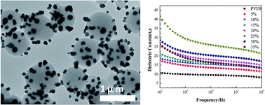
Polydopamine@AgNPs (PDA@AgNPs) core–satellite particles were fabricated by self-polymerization of dopamine and in situ reduction of Ag+ on the as-formed PDA surface. The PDA@AgNPs particles were introduced into poly(vinylidene difluoride) (PVDF) as fillers to prepare the PDA@AgNPs/PVDF composites. The employment of AgNPs could effectively increase the dielectric constant of the polymer composite. And the dielectric property of the composite could be regulated by the size of the PDA core. In addition, the core–satellite structure had the merit of preventing AgNPs from serious aggregation due to the immobilization on the PDA particles. Thanks to the bonding ability of PDA with various materials, this procedure shed light on the preparation of a number of new kinds of core–satellite particles with promising potentials in electronic fields.

1. Introduction

In recent years, with the rapid development of microelectronics and the electric power industry, the need for polymer composite materials with low cost and good dielectric performance is becoming more urgent.1–3 A variety of methods have been developed aiming to improve the dielectric constant of polymer composite materials. The traditional way is incorporating high dielectric constant inorganic ferroelectric ceramic particles into the polymer matrix. However, ceramic–polymer composites usually show low mechanical property and flexibility and poor adhesion.4–6 Another route is adding conductive fillers. The dielectric constant of the polymer composite could obtain a dramatic increase even when the conductive filler is employed at very low concentration. Among the conductive fillers, silver nanoparticles and nanofibers have gained a lot of attention due to their excellent thermal, electrical and optical properties. Especially, silver nanoparticles have been proven to be suitable fillers for dielectric composite materials. Lee et al. made barium titanate and silver as dispersed phase and polyimide as matrix, the dielectric constant could reach to more than 500.7 Yu et al. showed that by adding 40 vol% Ag@SiO2 and 20 vol% BaTiO3 into poly(vinylidene difluoride) (PVDF), the dielectric constant of the composite film was measured at 723.8 However, Ag particles are likely to aggregate in the matrix in the dispersion process which would harm the dielectric performance of the composites. Currently, one of the trends in this field is to construct special structured fillers such as core–shell or core–satellite particles.9–12 Under careful design, polymer composite materials with desired dielectric performance could be obtained through the construction of filler particles with special microstructures and electrical properties.

Dopamine (DA), a structural mimic of the mussel adhesive protein, has recently been considered as a robust and general surface building platform due to its strong interfacial adhesion.13 DA could spontaneously polymerize in alkaline solution and deposit on the surface of almost any kinds of materials including organic and inorganic materials due to the catechol and amine functional groups.14–17 Li et al. reported a composite film with dopamine coated ceramic particles as fillers. It was found that with the increase of filler contents, the dielectric constant increased, while the loss tangent remained constant in the frequency range of 103 to 105 Hz.18 Yang et al. prepared a SiO2/PDA/Ag/PDA multilayered shell particle and studied the dielectric property of its composite with poly(dimethyl siloxane).4 More recently, Zhang et al. created a AgNPs@PDA core–shell particle and incorporated into PVDF matrix. The dielectric performance of the polymer composite was effectively improved.19

Here, we present a new kind of dielectric composite with core–satellite structured PDA@AgNPs particles as fillers and PVDF as polymer matrix. The PDA@AgNPs particles were prepared by simple oxidative polymerization of DA and reaction with Ag+, where no excess reagents were involved. The AgNPs were scattered on the surface of the PDA spheres to form core–satellite structure. This special structure could prevent AgNPs from aggregation. The dielectric property of the composite films was carefully studied. And it was found the diameter of the PDA particles had an influence on the dielectric performance of the polymer composites.

2. Experimental

2.1. Materials

PVDF (type KF850) powder with density of 1.17–1.79 g cm−3 and melt flow index of 26 g × (10 min)−1 were purchased from Suzhou yimaishi plasticizing co. LTD (China). Silver nitrates were purchased from Sinopharm chemical reagent co. LTD (China). Hydrochloric acid, tris(hydroxymethyl) aminomethane (Tris) (99.9%), and N,N-dimethylmethanamide (DMF) were purchased from Beijing Chemical Plant (China). Dopamine hydrochlorides were purchased from Sigma Industrial Corporation (China). Ethanol was supplied by Lanyi Industrial Corporation (China).

2.2. Synthesis of PDA particles

The synthesis of PDA particles was carried out in water–ethanol mixed solvent. The typical preparation process is described as follows. Dopamine aqueous solution (1 mg mL−1) was prepared by dissolving dopamine (120 mg) in the Tris–HCl buffer solution (120 mL, 10 mM mixture based on deionized water and ethanol, Vwater[thin space (1/6-em)]:[thin space (1/6-em)]Vethanol = 5[thin space (1/6-em)]:[thin space (1/6-em)]1, pH = 8.5). Then the solution was kept magnetically stirring slowly at room temperature for 12 h. The obtained PDA particles were rinsed by an excess amount of deionized water for several times. Finally, the products were frozen in a −30 °C refrigerator for 5 h and then the powders were freeze-dried at a condenser with temperature of −50 °C under vacuum (10 Pa) for 8 h.

2.3. Synthesis of PDA@AgNPs particles

The as-synthesized PDA particles (about 30 mg) were dispersed in 80 mL deionized water and mixed with 40 mL AgNO3 aqueous solution. The concentration of AgNO3 solution was 2 mg mL−1 in the mixture. After stirred at room temperature for 3 h and washed by deionized water, the products were centrifuged and rinsed with deionized water for several times. Subsequently, the PDA@AgNPs particles were freeze-dried as same as the PDA particles.

2.4. Preparation of PDA@AgNPs/PVDF composites

A certain amount of PVDF powders were added into DMF at the temperature of 70 °C with mechanical agitation until the solution became transparent. PDA@AgNPs particles were ultrasonically dispersed in DMF. Then the two solutions were mixed together by mechanical stirring for 3 h in order to form a stable suspension. The mixture solution was cast onto a glass plate and dried under vacuum at 70 °C. Different ratios of PDA@AgNPs and PVDF were used to achieve a series of PDA@AgNPs/PVDF composite films with filler loadings of 5 wt%, 10 wt%, 15 wt%, 20 wt%, 25 wt%, 30 wt% and 35 wt%. The thickness of the achieved composite films was about 20 μm.

2.5. Characterization

The surface morphologies of the PDA particles, PDA@AgNPs particles and PDA@AgNPs/PVDF composite films were observed by scanning electron microscopy (SEM, HitachiS4700, Japan) operating at an accelerating voltage of 20 kV. The morphologies of the PDA and PDA@AgNPs particles were also achieved by Japan Hitachi H-7650B transmission electron microscopy (TEM). The crystal structures of the particles and composites were detected by X-ray diffraction (XRD). The elemental composition of PDA@AgNPs particles were carried out on an X-ray photoelectron spectroscopy (XPS, AXIS ULTRADLD Shimadzu Group Kratos Company). The patterns were recorded by a Rigaku DMAX-RB 12 kW rotating anode diffractometer. The dielectric property of composite films was measured by an impedance analyzer (Agilent 4294A) at room temperature over the frequency range of 102 to 106 Hz, and the samples were coated with copper by resistance high vacuum evaporation coating machine before test.

3. Results and discussion

The PDA particles were prepared by the self-polymerization of dopamine. The morphology of PDA spheres is shown in Fig. 1a. The diameter of the PDA spheres was about 500 nm. It could be seen that the shape of PDA spheres were almost spherical with smooth surfaces and uniform in size. It is essential to control the rate of polymerization of dopamine in preparation of monodispersed PDA particles. Therefore, ethanol was introduced here into the solvent which had the effect of manipulating the polymerization reaction of dopamine. The mechanism of dopamine polymerization could be described as follows. Under the weakly alkaline condition, the phenolic hydroxyl groups on the dopamine were oxidized by oxygen in the air and deprotonated to form dopamine quinone. Further, the inner ring of dopamine quinone rearranged to leukodopaminechrome and then continued to oxidized to 5,6-dihydroxyindole which was further oxidized and polymerized into crosslinked homopolymer.20 The PDA@AgNPs particles were prepared by the reaction between PDA particles and Ag ion. Due to the sufficient reductive capacity of PDA, no additional reducing agent was needed.21 According to the TEM image (Fig. 1b), the gray spheres showed the PDA core, AgNPs were shown by the dark region. AgNPs were immobilized on the PDA particles surfaces after the reduction with diameters ranging from tens of nanometers to a few hundreds. The immobilization of AgNPs was due to the metal binding ability of the catechols in PDA. The PDA particles and AgNPs together formed core–satellite structure.
image file: c6ra00827e-f1.tif
Fig. 1 (a) SEM image of PDA particles, (b) TEM image of PDA@AgNPs particles.

The chemical composition of PDA@AgNPs particles were determined by XPS spectra (Fig. 2). The strong peak at 284.8 eV was attributed to the binding energy of C. The N 1s spectrum had a signal at 399.9 eV, which was for amine N–H. The O 1s spectra composed two major signals, one at 532.1 eV (C–O) and the other one at 532.6 eV (O–H).22 The Ag 3d spectrums are shown in Fig. 2b. There were the two peak signals at binding energy of 368.05 eV and 374 eV for Ag 3d5/2 and Ag 3d3/2, respectively. These results proved the presence of PDA and Ag.


image file: c6ra00827e-f2.tif
Fig. 2 XPS spectra of PDA@AgNPs particles.

The as-prepared PDA@AgNPs particles were blended into PVDF by a series of contents. The crystalline structure of the PDA@AgNPs particles, PVDF film and PDA@AgNPs/PVDF were detected by XRD shown in Fig. 3. The five characteristic peaks of silver (2θ = 38.245°, 44.267°, 64.124°, 77.271° and 81.6°) could be seen in the PDA@AgNPs particles and PDA@AgNPs/PVDF samples, corresponding to Ag (111), Ag (200), Ag (220), Ag (311) and Ag (222) crystal planes, respectively. The PVDF crystals had three characteristic peaks at 2θ value of 18.6°, 20.4° and 39.3°. The highest diffraction peak at 2θ corresponding to 20.4 was assigned to β-PVDF.18 The weak diffraction peak centered at 18.6 and the broad peak centered at 39.3 were assigned to α-PVDF and γ-PVDF, respectively.


image file: c6ra00827e-f3.tif
Fig. 3 XRD spectra of PDA@AgNPs particles, PVDF film and PDA@AgNPs/PVDF composite. The filler loading of the composite film was 25 wt%.

The SEM images of the cross-sections of the PDA@AgNPs/PVDF composite films with various filler loadings are presented in Fig. 4. It can be seen that the PDA@AgNPs particles were homogenously dispersed in PVDF matrix when the filler loading were from 5 wt% to 30 wt%. The distance between PDA@AgNPs particles decreased with the increasing content of the particles. When the content of the filler particles increased to 30 wt%, almost all the particles were in contact with each other. With filler loading reaching to 35 wt%, the PDA@AgNPs particles showed a small degree of agglomeration in the matrix.


image file: c6ra00827e-f4.tif
Fig. 4 SEM images of PDA@AgNPs/PVDF composite films with various filler loading. (a) 5 wt%, (b) 10 wt%, (c) 15 wt%, (d) 20 wt% (e) 25 wt%, (f) 30 wt% and (g) 35 wt%.

The dielectric properties of the PDA@AgNPs/PVDF composite films are shown in Fig. 5. The dielectric constant of pure PVDF was about 10 at 102 Hz. When 5 wt% particles were added, dielectric constant increased to 17.5. As the content of filler increased, the dielectric constant of composite film also increased slowly. When the filler content was 25 wt%, the dielectric constant of the composite reached peak at 41.7, which was 4 times as high as that of PVDF matrix. Then, the dielectric constant of the composites decreased with the increase of PDA@AgNPs content. The overall increase of the dielectric constant could be described to the incorporation of the AgNPs which were conductive fillers with the ability to enhance the electric field in the matrix. And the decrease took place after the filler loading reached over 25 wt% was due to the over inclusion of the PDA, which was a semiconductor with low dielectric constant. The dielectric loss of the composite films was related to the frequency and the mass fraction of fillers, shown in Fig. 5b. The dielectric loss of the PDA@AgNPs/PVDF composite films increased with the increasing filler loading first and then reduced. When the filler content was 25 wt%, the dielectric loss reached to 0.38 at 102 Hz. In our previous work, Ag@PDA/PVDF composites were prepared using core–shell Ag@PDA as fillers and PVDF as matrix.19 In comparison, at the filler loading of 25 wt%, the core–shell filler system had higher dielectric constant at 53.0 than that of 41.7 of this core–satellite composite. This is likely due to the concentration of AgNPs in the core–shell filler composite was 16.7 wt%, slightly higher than the core–satellite filler composite, which was 15.9 wt%. However, the dielectric loss of the PDA@AgNPs/PVDF composite was lower than the Ag@PDA/PVDF composite, which was 0.38 compared to 0.52. This is not only due to the less AgNPs incorporation, but also the fillers' unique core–satellite microstructure. The scattering of the AgNPs on the PDA core could effectively prevent them from aggregation. Thus it could lower the dielectric loss which is important for dielectric materials.


image file: c6ra00827e-f5.tif
Fig. 5 Frequency dependence of (a) dielectric constant and (b) dielectric loss tangent of PDA@AgNPs/PVDF composite films with various filler loadings.

The dielectric properties of the PDA@AgNPs/PVDF composite films could be controlled by adjusting the size of the PDA particles. The particle size was regulated by the pH values of the dopamine solution during the PDA preparation process. With other conditions fixed, the pH values of the solutions dissolving dopamine were set at 7.5, 8.0, 8.5, and 9.0, respectively. The achieved PDA particles had diameters of about 200 nm, 300 nm, 500 nm, 550 nm, accordingly (Fig. 1 and S1). The diameter of PDA spheres decreased with the decrease of the pH value of Tris–HCl buffer solution. When the PDA particle size was 200 nm, the dielectric constant of the composite was 18.7 (Fig. 6). When the diameter increased to 300 nm, the dielectric constant increased to 20.9. It could be seen that when the PDA particle size was 500 nm, the composite had better dielectric performance compared to the others. The dielectric constant was 41.7 when the frequency was 102 Hz. Then, with increasing the particle size, the dielectric constant decreased slightly. The dielectric loss of the composites showed similar trend. This result is owing to the change of the AgNPs concentration in the composites. For the composites with PDA diameters ranged from 200 nm to 550 nm, the AgNPs concentration was 6.9 wt%, 8.2 wt%, 15.9 wt% and 14.3 wt%, accordingly. Both dielectric constant and dielectric loss showed the same trend with the changing AgNPs concentration.


image file: c6ra00827e-f6.tif
Fig. 6 Frequency dependence of (a) dielectric constant and (b) dielectric loss of PDA@AgNPs/PVDF composite films using PDA@AgNPs particles with varied PDA size. The filler loading was 25 wt%.

4. Conclusions

A dielectric polymer composite material was fabricated using a new kind of core–satellite structured filler. The fillers were constructed by PDA spheres as core and AgNPs as satellite particles. The introduction of AgNPs could increase the dielectric constant of the composite. The composite film achieved the highest dielectric constant at about 41.7 with 25 wt% filler loading at 100 Hz. The size of the core PDA particles could influence the dielectric property of the composite film. The core–satellite structure insured the homogenous dispersion of the AgNPs in the polymer matrix by immobilizing the AgNPs on the PDA particles. The dielectric property of the composite may be improved by the number, size or distance of the satellite particles, which is an on-going research in our group. Due to the bonding ability of PDA with various materials, this strategy could be extended to preparation of a variety of core–satellite filler particles with potential applications in electronic fields.

Acknowledgements

This work was supported by NSFC (No. 51303010, 51425201, 51377010), Specialized Research Fund for the Doctoral Program of Higher Education (20130006120019, 20130006130002) and the National Basic Research Program of China (973 Program, No. 2015CB654603).

Notes and references

  1. G. S. Wang, ACS Appl. Mater. Interfaces, 2010, 2, 1290 CAS.
  2. Y. Dan, M. Tian, D. D. Li, W. C. Wang, F. X. Ge and L. Q. Zhang, J. Mater. Chem. A, 2013, 1, 12276 Search PubMed.
  3. Y. Song, Y. Shen, H. Y. Liu, Y. H. Yuan, M. Li and C. W. Nan, J. Mater. Chem., 2012, 22, 8063 RSC.
  4. Y. Dan, M. Tian, W. C. Wang, D. D. Li, R. Y. Li, H. L. Liu and L. Q. Zhang, Electrochim. Acta, 2013, 87, 9 CrossRef.
  5. W. Zheng, X. F. Lu, W. Wang, Z. J. Wang, M. X. Song, Y. Wang and C. Wang, Phys. Status Solidi A, 2010, 207, 1870 CrossRef CAS.
  6. R. Saha and B. K. Mandal, J. Appl. Polym. Sci., 2010, 117, 122 CrossRef CAS.
  7. N. G. Devaraju and B. I. Lee, J. Appl. Polym. Sci., 2006, 99, 3018 CrossRef CAS.
  8. X. W. Liang, S. H. Yu, R. Sun, S. B. Luo and J. Wan, J. Mater. Res., 2012, 27, 991 CrossRef CAS.
  9. S. Kang, M. Baginska, S. R. White and N. R. Sottos, ACS Appl. Mater. Interfaces, 2015, 7, 10952 CAS.
  10. K. Yang, X. Y. Huang, J. L. He and P. K. Jiang, Adv. Mater. Interfaces, 2015, 2, 1500361 Search PubMed.
  11. L. W. Wu, X. H. Wang, H. L. Gong, Y. N. Hao, Z. B. Shen and L. T. Li, J. Mater. Chem. C, 2015, 3, 750 RSC.
  12. L. Y. Xie, X. Y. Huang, B. W. Li, C. Y. Zhi, T. Tanakae and P. K. Jiang, Phys. Chem. Chem. Phys., 2013, 15, 17560 RSC.
  13. V. K. Thakur, M.-F. Lin, E. J. Tana and P. S. Lee, J. Mater. Chem., 2012, 22, 5951 RSC.
  14. Y. Zhao, Y. Yeh, R. Liu, J. M. You and F. L. Qu, Solid State Sci., 2015, 45, 9 CrossRef CAS.
  15. J. Liebscher, R. Mrówczyński, H. A. Scheidt, C. Filip, N. D. Hădade, R. Turcu, A. Bende and S. Beck, Langmuir, 2013, 29, 10539 CrossRef CAS PubMed.
  16. L. J. Zhu, Y. L. Lu, Y. Q. Wang, L. Q. Zhang and W. C. Wang, Appl. Surf. Sci., 2012, 258, 5387 CrossRef CAS.
  17. H. W. Yang, Y. Lan, W. Zhu, W. N. Li, D. Xu, J. C. Cui, D. Z. Shen and G. T. Li, J. Mater. Chem., 2012, 22, 16994 RSC.
  18. B. C. Luo, X. H. Wang, Y. P. Wang and L. T. Li, J. Mater. Chem. A, 2014, 2, 510 CAS.
  19. L. Zhang, S. Yuan, S. Chen, D. R. Wang, B. Z. Han and Z. M. Dang, Compos. Sci. Technol., 2015, 110, 126 CrossRef CAS.
  20. J. Yan, L. P. Yang, M. F. Lin, J. Ma, X. H. Lu and P. S. Lee, Small, 2013, 9, 596 CrossRef CAS PubMed.
  21. J. Leng, X. L. Wen, J. N. Rao, G. Zou and Q. J. Zhang, Polymer, 2012, 53, 1543 CrossRef CAS.
  22. D. X. Yang, A. Velamakanni, G. Bozoklu, S. Park, M. Stoller, R. D. Piner, S. Stankovich, I. Jung, D. A. Field, C. A. Ventrice Jr and R. S. Ruoff, Carbon, 2009, 47, 145 CrossRef CAS.

Footnote

Electronic supplementary information (ESI) available. See DOI: 10.1039/c6ra00827e

This journal is © The Royal Society of Chemistry 2016
Click here to see how this site uses Cookies. View our privacy policy here.