Control of osmotic pressure through CO2-capture and release facilitated by the lower critical solution temperature (LCST) phase transition of acylated branched polyethylenimine

Jeongseon Parka, Minwoo Noha, Min Keun Cheya, Yeongbong Moka, Ji-Hun Seob and Yan Lee*a
aDepartment of Chemistry, Seoul National University, Gwanak-ro 1, Gwanak-gu, Seoul 151-747, Republic of Korea. E-mail: gacn@snu.ac.kr
bDepartment of Materials Science and Engineering, Korea University, 145 Anam-ro, Seongbuk-gu, Seoul 136-701, Republic of Korea

Received 6th January 2016 , Accepted 27th February 2016

First published on 4th March 2016


Abstract

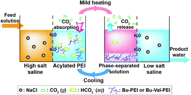
A solution of acylated polyethylenimine can absorb CO2 at low temperatures to elevate the osmotic pressure and draw water from a high-salt saline solution. Such a solution can be phase-separated to liberate CO2 by mild heating at 40 °C, and the osmotic pressure can be effectively reduced for water release into a low-salt saline solution. The osmotic pressure-controlling system has the potential to be used as a draw solution for forward osmosis.


The shortage of fresh water represents an imminent global problem. Although seawater accounts for 97% of all water on Earth, most of it cannot be used for drinking or agriculture because of its high salinity. While distillation and reverse-osmosis (RO) are the two most common commercially available methods of desalination, the forward-osmosis (FO) method has been actively investigated because of its energy efficiency. FO desalination utilizes a draw solute to raise the osmotic pressure of a solution to be higher than that of seawater, which results in the induction of osmotic flow through a semi-permeable membrane to draw water from seawater. Subsequently, the draw solutes are typically removed to yield freshwater.1

Ideally, for efficient and practical FO, a draw solute must satisfy several criteria. First, it should induce high osmotic pressure for effective water drawing from high-salt saline solutions. Secondly, the draw solute should be easily separated from the solution with minimal energy input after the drawing process is complete. Finally, the draw solute should be easily recovered and reusable for multiple desalination processes.

The most extensively studied draw solute for FO desalination is ammonium bicarbonate (NH4HCO3).2 NH4HCO3 meets, at least in part, several of the listed requirements for an ideal draw solute. Highly concentrated NH4HCO3 solutions induce high osmotic pressure to draw water from seawater. Thereafter, NH4HCO3 thermally decomposes into gaseous ammonia (NH3) and carbon dioxide (CO2), which can be removed from the draw solution afterwards. However, separating NH4HCO3 from the draw solution requires a high-energy input (>60 °C) for the decomposition of NH4HCO3. Moreover, a complex distillation-based removal process is required to completely remove the decomposed NH3 from the acquired water. Therefore, extensive research efforts have aimed to overcome the weaknesses associated with the pre-existing draw solutes.3

Meanwhile, amine-rich polymers such as branched polyethylenimine (b-PEI) are well-known as CO2 absorbers because the alkaline amine residues can strongly interact with carbonic acid (H2CO3), a hydrated form of CO2, in water and thereby increase the aqueous solubility of CO2.4 Based on the same rationale for the NH4HCO3-based FO, we expected that the amine-rich polymers have a potential to be used as FO draw solutes if the absorbed CO2 can be readily released from the aqueous solution of the polymers by mild temperature change.

Herein, we introduced lower critical solution temperature (LCST) properties to the amine-rich polymer for facilitating release of CO2 from the polymeric solution. At certain temperatures, LCST polymers exhibit abrupt phase separation from solvents.5 As shown in Fig. 1, at lower temperatures below the phase transition temperature, the amine-rich LCST polymer would raise the osmotic pressure of the solution by CO2 absorption and the generation of bicarbonate anions (HCO3), whereas at slightly higher temperatures above the phase transition temperature, the polymer would separate from the solution, resulting in the discharge of gaseous CO2 and a dramatic reduction of the osmotic pressure. Because the phase transition temperature of the LCST polymer can reflect the polymeric structure,6 the trigger temperature for controlling the osmotic pressure can be reduced to a temperature far below the decomposition temperature of NH4HCO3. Furthermore, the phase-separated LCST polymer could be easily removed and recycled. Some LCST polymers have been developed as draw solutes using temperature-dependent phase separation, but insufficient drawing activity or a high phase transition temperature has limited their practical use in desalination.7 Therefore, we propose an FO control system by combination of the CO2-aborbing property of an amine-rich polymer for the powerful drawing activity at a low temperature and the LCST property for the efficient CO2 release and recycling at a high temperature.


image file: c6ra00371k-f1.tif
Fig. 1 Schematic diagram of osmotic pressure-controlling system by temperature-sensitive absorption and release of CO2 based on LCST materials.

In previous reports, the LCST phase transition temperature of polymers has been shown to be easily controlled by simple acylation procedures.8 We acylated b-PEI by the same method for obtaining an amine-rich polymer with LCST property (Fig. S1, ESI). Four-carbon butyryl (Bu) group and five-carbon valeroyl (Val) group were introduced to the b-PEI backbone for the control of hydrophobicity and subsequently the phase transition temperature. Among the amine moieties in the b-PEI backbone, most primary and secondary amines were reacted to provide hydrophobic acyl groups, and the remaining tertiary amines could act as CO2-absorbing moieties in the draw solution.

The LCST phase separation could be observed by changes in the transmittance of an aqueous solution of acylated b-PEI.8 As shown in Fig. 2a, the transmittance of Bu–PEI solution dropped abruptly at the phase transition temperature, 40 °C. However, phase separation of the CO2-saturated Bu–PEI solution could be observed at 60 °C, a significantly higher temperature compared with the original phase transition temperature. The more hydrophobic Bu–Val–PEI has a lower phase transition temperature than does Bu–PEI. The phase separation temperatures of Bu–Val–PEI and CO2-saturated Bu–Val–PEI solutions were observed to occur at 20 °C and 27 °C, respectively, which were both significantly lower than those respective temperatures of Bu–PEI (Fig. 2b). In both solutions, CO2 saturation increased the phase transition temperature. Dissolved CO2 produces H2CO3 and subsequently forms a bicarbonate salt with a tertiary amine in the polymer backbone. The protonated ammonium residues may reverse the hydrophobic effects of the alkyl group, which could elevate the phase transition temperature.9


image file: c6ra00371k-f2.tif
Fig. 2 LCST phase transition of 3.4 m Bu–PEI (a) and 1.7 m Bu–Val–PEI (b) in CO2-free (●) and CO2-saturated (○) conditions.

Next, we examined whether CO2 absorption and release into the polymeric solution could be controlled by the LCST phase transition induced by mild changes in temperature. The CO2 content in the polymer solution was calculated by measuring the pH and the CO2-saturated condition was normalised to 100% of CO2 content.10 Fig. 3a compares the kinetics of CO2 absorption and release of b-PEI and Bu–PEI solutions with temperatures that varied between 25 °C and 70 °C. At 25 °C, CO2 was gradually absorbed into both solutions. The absorption rate into b-PEI was somewhat faster, but CO2 saturation was also observed in the Bu–PEI solution after 1 h of CO2 bubbling. At 70 °C, CO2 was released from the phase-separated Bu–PEI solution. Specifically, 60–80% of pre-absorbed CO2 was released within 20 min of heating, and 10–15% of CO2 was gradually released by an additional 100 min of heating. Release of CO2 from the non-phase-separated b-PEI solution was much slower than that of Bu–PEI (Fig. S3a, ESI).


image file: c6ra00371k-f3.tif
Fig. 3 (a) CO2 absorption (25 °C) and release (70 °C) of b-PEI (△) and Bu–PEI (●) solutions at the amine concentration of 3.4 m. (b) CO2 absorption (15 °C) and release (40 °C) of b-PEI (●), Bu–PEI (○), and Bu–Val–PEI (▼) solutions at the amine concentration of 1.7 m.

Furthermore, we compared the CO2 absorption and release kinetics of the Bu–Val–PEI solution with those of b-PEI and Bu–PEI solutions at a lower temperature range between 15 °C and 40 °C (Fig. 3b). The absorption rate of the Bu–Val–PEI solution was similar to that of the Bu–PEI solution, showing saturation after 30 min of CO2 bubbling, which was lower than that of b-PEI at 15 °C. The Bu–Val–PEI solution could be phase-separated and release CO2 at 40 °C. The release rate of CO2 from the Bu–Val–PEI solution was much faster than those from non-phase-separated b-PEI and Bu–PEI solutions (Fig. S3b, ESI). Within 10 min of heating at 40 °C, 60% of the absorbed CO2 was released from the Bu–Val–PEI solution. By contrast, b-PEI and Bu–PEI released only 10–20% of CO2 during the same heating time. In both CO2-releasing experiments at 70 °C and 40 °C, the phase-separated solutions showed higher releasing rate than non-phase-separated solutions. The introduction of LCST property by acylation clearly facilitated the release of absorbed CO2 induced by temperature change. The rapid release of CO2 from the Bu–Val–PEI solution by mild heating at 40 °C might effectively reduce the energy requirement for the FO system because CO2 can be released from NH4HCO3 solutions or other LCST polymer-based draw solutions at a temperature around 60 °C and most of energy is consumed for the process of separation and recovery of draw solutes in the FO system.2,3 During three-successive bubbling–heating cycles, all polymeric solutions exhibited similar absorption-release kinetics.

As the acylated PEI solutions showed efficient absorption and release of CO2 in response to mild changes in temperature, we could apply them as draw solutions for FO. The solutions would increase the osmotic pressure to draw water from a high-salt solution by absorbing CO2 at a low temperature, whereas at high temperature they would reduce the osmotic pressure to release water into a low-salt solution by discharging CO2. Fig. 4 shows osmotic flux between NaCl solutions and the acylated PEI solutions with varying temperatures. A Bu–PEI solution with an amine concentration of 3.4 m (molality) clearly showed high osmotic flux from NaCl solutions at 25 °C (Fig. 4a). This solution could draw water from a seawater equivalent (0.60 m NaCl solution), even in CO2-free conditions. In CO2 saturating conditions, the solution exhibited approximately 1.5–2-fold faster osmotic flux compared with the CO2-free solution. It was confirmed that dissolved CO2 and the resulting HCO3 could raise the actual osmotic pressure for effective drawing. The CO2-saturated Bu–PEI solution was subsequently heated to 70 °C to obtain a clear phase separation into a water-rich upper layer and a solute-rich lower layer. The osmotic pressure of the upper layer was sufficiently low to release the drawn water into low-salt solutions. The CO2-free Bu–PEI solution could release water into a NaCl solution that had a concentration of 0.10 m (Fig. 4b). The dissolved CO2 could be effectively liberated from the solution by phase separation to reduce the osmotic pressure.


image file: c6ra00371k-f4.tif
Fig. 4 Osmotic flux (a) from NaCl solutions to a Bu–PEI solution (amine concentration: 3.4 m) at 25 °C and (b) from the upper layer of the Bu–PEI solution to NaCl solutions at 70 °C. Osmotic flux (c) from NaCl solutions to a Bu–Val–PEI solution (amine concentration: 1.7 m) at 15 °C and (d) from the upper layer of the Bu–Val–PEI solution to NaCl solutions at 40 °C. CO2-free and CO2-saturated conditions are represented as white and grey bars, respectively. Each error bar means the standard deviation of three measurements.

Bu–Val–PEI has relatively low aqueous solubility because of the inherent hydrophobicity introduced by its valeroyl group, so a solution with an amine concentration of 1.7 m was used instead. Although the CO2-free Bu–Val–PEI solution could not induce osmotic pressure that was sufficiently low to draw water from a seawater equivalent, or even a 0.30 m NaCl solution, CO2-saturated Bu–Val–PEI did exhibit 2–3-fold enhanced osmotic flux from NaCl solutions with concentrations below 0.15 m, and they could barely draw water from 0.30 m NaCl solution at 15 °C (Fig. 4c). Similarly to the aforementioned studies, CO2 absorption effectively increased the drawing osmotic flux. The Bu–Val–PEI solution was phase-separated into a water-rich upper layer and a solute-rich lower layer at 40 °C. The osmotic pressure of the upper layer was reduced by the discharge of CO2 so that the release of water into a 0.10 m NaCl solution could be observed (Fig. 4d). The LCST phase separation of polymers represents the key-point for the control of CO2-dependent osmotic pressure by mild changes in temperature, the polymeric solutions in non-phase-separated conditions (b-PEI at 70 °C and 40 °C or Bu–PEI at 40 °C) show only limited change of osmotic fluxes and could not release water into a 0.15 m NaCl solution (Fig. S4, ESI). Based on these findings, we predicted that an FO system that could draw water with absorption of CO2 at 15 °C and release water with discharge of CO2 at 40 °C using Bu–Val–PEI. The temperature change between 15 °C and 40 °C might be achieved with a low energy cost if energy from waste heat or sunlight is used. Moreover, the phase-separated lower layer could be easily recycled for the second drawing-release cycle.

In summary, we prepared an efficient osmotic pressure-control system based on LCST phase separation and CO2 absorption-release. Acylated PEI with tertiary amines can serve as a CO2 absorber at a low temperature, but can be phase-separated to facilitate the discharge of CO2 by mild heating. Dissolved CO2 can elevate the osmotic pressure needed for water drawing, and the discharge of CO2 can reduce the osmotic pressure to allow for water release. The CO2-release temperature can be easily tailored by controlling the hydrophobicity of the structure of acylated PEI. Notably, Bu–Val–PEI could effectively liberate the dissolved CO2 at 40 °C, which is a far lower temperature compared with other previously reported CO2-based drawing solutes such as switchable polarity solvents and CO2-switchable polymers, without inert gas purging, which is required for phase separation.7 Although Bu–PEI and Bu–Val–PEI have strong potential for use as drawing solutes in desalination or water purification applications, several hurdles, such as the relatively high phase transition temperature (Bu–PEI) and low aqueous solubility (Bu–Val–PEI), remain to be overcome before their application in practical FO systems. In future studies, we intend to find an ideal balance between low phase transition temperatures and aqueous solubility that is appropriate for FO desalination by attaching various other hydrophobic alkyl groups to b-PEI and adjusting the degrees of acylation. Furthermore, detailed analyses of the energy requirements will be carried out to improve our design of a practical FO system in the future.

Experimental section

Preparation of Bu–PEI and Bu–Val–PEI

The scheme used to synthesize Bu–PEI and Bu–Val–PEI is shown in Fig. S1, ESI. For the synthesis of Bu–PEI, 50 g b-PEI (0.87 mol reactive amines) was dissolved in 600 mL methanol. An aqueous solution of NaHCO3 (1.0 M, 600 mL) was added to the solution as a proton quencher during the synthesis. Then, 140 mL n-butyric anhydride (0.87 mol, 1.0 eq.) was added drop-wise to the solution. The mixture was stirred for 1 h in an ice bath and then overnight at ambient temperature. For better extraction, an aqueous solution of NaOH (1.0 M) was added until the solution reached pH 11. The Bu–PEI was collected by extraction with dichloromethane (×3). The combined organic layer was evaporated to yield Bu–PEI as an opaque yellow viscous gel (yield > 90%). For the synthesis of Bu–Val–PEI, 100 g b-PEI (1.7 mol reactive amines) was dissolved in methanol (1200 mL). Subsequently, 24 mL TEA (0.17 mol; 0.10 eq.) was added to the solution as a proton quencher. With vigorous stirring of the solution, 21 mL valeroyl chloride (0.17 mol; 0.10 eq.) was added drop-wise to the solution, which was subsequently stirred in an ice bath for 1 h. After further stirring at ambient temperature for several hours, gaseous hydrochloric acid that had formed during the acylation reaction was removed by purging with N2 gas. The solution was concentrated by evaporating the methanol solvent. The remaining reaction mixture was purified by ether precipitation (×3) and valeroylated b-PEI (Val–PEI) was collected as a precipitate. After drying, Val–PEI was obtained as an opaque yellow viscous gel (yield > 90%). The remaining reactive amines of Val–PEI were further acylated by n-butyric anhydride following a similar procedure using Bu–PEI to produce Bu–Val–PEI, which was an opaque yellow viscous gel (yield > 90%). The 1H NMR spectra of Bu–PEI and Bu–Val–PEI are shown in Fig. S2, ESI.

Measurement of the LCST phase transition

Changes in light turbidity were measured at a wavelength of 600 nm to monitor the LCST phase transition of the polymeric solutions. Sample solutions were prepared at concentrations of 3.4 m or 1.7 m in water for Bu–PEI and Bu–Val–PEI, respectively. CO2-saturated polymer solutions were prepared by CO2 bubbling (100 mL min−1) for 1 h. Temperature-dependent changes in the transmittance of each sample solution was measured using a V-650 UV-Vis spectrophotometer (Jasco, Japan) at a heating rate of 0.5 °C min−1. The phase transition temperature is defined as the temperature at which the transmittance is 50% during the heating.

Measurements of CO2 absorption and release

The CO2 content was measured and calculated based on the pH of the polymeric solutions during the absorption and release cycles. During CO2 absorption, pH values were automatically measured using a S470 SevenExcellence™ pH/conductivity (Mettler Toledo, Switzerland) every 5 min. During heating, samples were collected at 10 min intervals. Those samples were cooled and the pH was measured using a LAQUAtwin Compact pH Meter (Horiba, Japan). The pH data were analyzed and used to calculate the CO2 content.10

Measurements of osmotic flux

Osmotic flux was measured using handmade glass tubes in a temperature-controlled water bath.11 A semi-permeable membrane (cellulose triacetate membrane cast on a non-woven backing consisting of polyester fibers coated with polyethylene; NW-CTA) was provided by Hydration Technology Innovation (USA). A membrane (diameter: 3.5 cm) was placed in the middle of the upper and lower tubes, and each tube was filled with NaCl and LCST polymer solutions, respectively, with stirring. The active layer of the semi-permeable membrane was oriented to face the polymer solution. The osmotic water flux from the NaCl solution to the LCST mixture was calculated based on the volumetric change of each solution over 0.5 h after 0.5 h stabilization at either 25 °C or 15 °C (±2 °C). The reverse osmotic flux from the polymeric to the NaCl solution was similarly calculated at 70 °C or 40 °C (±2 °C).

Acknowledgements

This work was supported by the GAIA project (G113-00055-3004-0) funded by Ministry of Environment, Korea, and by the National Research Foundation of Korea Grant funded by the Korean Government (NRF-2015052185).

Notes and references

  1. R. E. Karavath and J. A. Davis, Desalination, 1975, 16, 151 CrossRef CAS ; T. Y. Cath, A. E. Childress and M. Elimelech, J. Membr. Sci., 2006, 281, 70 CrossRef ; D. Li and H. Wang, J. Mater. Chem. A, 2013, 1, 14049 Search PubMed ; Q. Ge, M. Ling and T.-S. Chung, J. Membr. Sci., 2013, 442, 225 CrossRef ; W. Ye, J. Lin, H. T. Madsen, E. G. Søgaard, C. H. Nielsen, P. Luis and B. Van der Bruggen, J. Membr. Sci., 2016, 498, 75 CrossRef .
  2. J. R. McCutcheon, R. L. McGinnis and M. Elimelech, Desalination, 2005, 174, 1 CrossRef CAS ; J. R. McCutcheon, R. L. McGinnis and M. Elimelech, J. Membr. Sci., 2006, 278, 114 CrossRef ; A. Subramani and J. G. Jacangelo, Water Res., 2015, 75, 164 CrossRef PubMed .
  3. Q. Zhao, N. Chen, D. Zhao and X. Lu, ACS Appl. Mater. Interfaces, 2013, 5, 11453 Search PubMed ; A. Zhou, H. Luo, Q. Wang, L. Chen, T. C. Zhang and T. Tao, RSC Adv., 2015, 5, 15359 RSC ; D. Li, X. Zhang, J. Yao, G. P. Simon and H. Wang, Chem. Commun., 2011, 47, 1710 RSC ; A. Razmjou, Q. Liu, G. P. Simon and H. Wang, Environ. Sci. Technol., 2013, 47, 13160 CrossRef CAS PubMed ; D. Zhao, S. Chen, P. Wang, Q. Zhao and X. Lu, Ind. Eng. Chem. Res., 2014, 53, 16170 CrossRef ; C. X. Guo, D. Zhao, Q. Zhao, P. Wang and X. Lu, Chem. Commun., 2014, 50, 7318 RSC .
  4. M. Yue, Y. Hoshino, Y. Ohshiro, K. Imamura and Y. Miura, Angew. Chem., 2014, 126, 2692 CrossRef CAS ; P. Li, B. Ge, S. Zhang, S. Chen, Q. Zhang and Y. Zhao, Langmuir, 2008, 24, 6567 CrossRef PubMed ; E. Andreoli, E. P. Dillon, L. Cullum, L. B. Alemany and A. R. Barron, Sci. Rep., 2014, 4, 7304 CrossRef PubMed .
  5. R. B. Griffiths and J. C. Wheeler, Phys. Rev. A: At., Mol., Opt. Phys., 1970, 2, 1047 CrossRef .
  6. S. Salmaso, P. Caliceti, V. Amendola, M. Meneghetti, J. P. Magnusson, G. Pasparakis and C. Alexander, J. Mater. Chem., 2009, 19, 1608 RSC .
  7. M. L. Stone, C. Rae, F. F. Stewart and A. D. Wilson, Desalination, 2013, 312, 124 CrossRef CAS ; Y. Cai, W. Shen, R. Wang, W. B. Krantz, A. G. Fane and X. Hu, Chem. Commun., 2013, 49, 8377 RSC ; Y. Cai, W. Shen, J. Wei, T. H. Chong, R. Wang, W. B. Krantz, A. G. Fane and X. Hu, Environ. Sci.: Water Res. Technol., 2015, 1, 341 Search PubMed ; D. Han, X. Tong, O. Boissière and Y. Zhao, ACS Macro Lett., 2012, 1, 57 CrossRef .
  8. H. Kim, S. Lee, M. Noh, S. H. Lee, Y. Mok, G. Jin, J.-H. Seo and Y. Lee, Polymer, 2011, 52, 1367 CrossRef CAS .
  9. J.-H. Suh, H.-J. Paik and B. Hwang, Bioorg. Chem., 1994, 22, 318 CrossRef CAS ; Y. Yang, A. J. Mijalis, H. Fu, C. Agosto, K. J. Tan, J. D. Batteas and D. E. Bergbreiter, J. Am. Chem. Soc., 2012, 134, 7378 CrossRef PubMed .
  10. P. Singh, J. P. M. Niederer and G. F. Versteeg, Chem. Eng. Res. Des., 2009, 87, 135 CrossRef CAS ; A. Dibenedetto, C. Pastore, C. Fragale and M. Aresta, ChemSusChem, 2008, 1, 742 CrossRef PubMed ; J. N. Cameron and D. J. Randall, J. Exp. Biol., 1972, 57, 673 Search PubMed ; F. Mani, M. Peruzzinib and P. Stoppionia, Green Chem., 2006, 8, 995 RSC ; W. F. Boron and P. D. Weer, J. Gen. Physiol., 1976, 67, 91 CrossRef PubMed ; H. Bai and A. C. Yeh, Ind. Eng. Chem. Res., 1997, 36, 2490 CrossRef .
  11. M. Noh, Y. Mok, S. Lee, H. Kim, S. H. Lee, G.-W. Jin, J.-H. Seo, H. Koo, T. H. Park and Y. Lee, Chem. Commun., 2012, 48, 3845 RSC ; Y. Mok, D. Nakayama, M. Noh, S. Jang, T. Kim and Y. Lee, Phys. Chem. Chem. Phys., 2013, 15, 19510 RSC ; D. Nakayama, Y. Mok, M. Noh, J. Park, S. Kang and Y. Lee, Phys. Chem. Chem. Phys., 2014, 16, 5319 RSC .

Footnote

Electronic supplementary information (ESI) available: The synthetic scheme and H-NMR spectra of acylated PEI, and osmotic flux data. See DOI: 10.1039/c6ra00371k

This journal is © The Royal Society of Chemistry 2016