
 Open Access Article
 This Open Access Article is licensed under a
 Creative Commons Attribution 3.0 Unported Licence
Electrospun nanofiber SLIPS exhibiting high total transparency and scattering†
Jyunichiro
Abe
,
Mizuki
Tenjimbayashi
and
Seimei
Shiratori
*
Department of Integrated Design Engineering, Faculty of Science and Technology, Keio University, 3-14-1 Hiyoshi, Kohoku-ku, Yokohama, Kanagawa 223-8522, Japan. E-mail: shiratori@appi.keio.ac.jp
First published on 8th April 2016
Abstract
Antifouling coatings are important in fields such as mobility, architecture, power generation devices, and medical devices, where energy efficiency is required to be maximized. Slippery liquid-infused porous surfaces (SLIPS) are an antifouling approach inspired by nature from the pitcher plant, and have recently received widespread attention in many fields. SLIPS can repel various liquids, including organic solvents with low contact angle hystereses, but require further development to extend their application. We previously reported a fast and straight-forward process for preparing SLIPS called Gel-SLIPS. SLIPS were prepared by the non-solvent-induced phase separation (NIPS) of a poly(vinylidene fluoride-co-hexafluoropropylene) (PVDF–HFP)/di-n-butyl phthalate solution. In the current study, SLIPS were prepared by electrospinning to give nanofiber SLIPS. These exhibited high scattering (50%), high total transmittance (93.2%), and a low sliding angle (≤10°). These properties resulted from the nanofiber non-woven structure of the PVDF–HFP. Nanofiber SLIPS provide control over scattering by altering the under layer density, all while maintaining the total transparency. These characteristics are useful for energy efficient optical devices such as solar cells and street lighting.
1. Introduction
Antifouling coatings are used in various applications to prevent performance degradation due to fouling. For example, fouling lowers the power generation performance of solar cells.1–4 Various antifouling coatings have been investigated, such as hydrophobic coatings inspired by the lotus-leaf effect,5 and coatings based on semiconductor photocatalysis.6–8 However, these approaches suffer from low durability and limited application conditions. Antifouling coatings based on slippery liquid-infused porous surfaces (SLIPS) have attracted much recent attention for overcoming these problems.9,10 SLIPS are a kind of biomimetic of Nepenthes, produced by infusing lubricant oil into the hydrophobic underlying layer.SLIPS consist of a lubricant of low surface energy, and an under layer of low surface energy. The lubricant protects the structure of the under layer, so SLIPS can overcome problems associated with conventional antifouling approaches, such as their limited effect on low surface tension organic solvents, and susceptibility to physical damage and pressure. However, the hydrophobic under layer of conventional SLIPS are produced by a complex process.11,12 We previously fabricated the under layer of a poly(vinylidene fluoride-co-hexafluoropropylene) (PVDF–HFP) membrane, by a simple process called non-solvent-induced phase separation (NIPS). The PVDF–HFP membrane was used to fabricate SLIPS.13 The antifouling coating was named SLIPS, on account of it being inspired by the PVDF–HFP-gel-electrolyte of lithium ion batteries (LIBs).14 NIPS is a simple process for preparing micro-sized porous structures, and is based on self-organized phase separation at ambient temperature and pressure. NIPS can be used in various fields, such as air and water filtration/purification processes,15 and LIB separators.16,17 However, NIPS suffers from its inability to easily fabricate high surface roughness, and requires large amounts of organic solvent. The PVDF–HFP membrane previously prepared by NIPS exhibited a low surface roughness of Rrms ≤ 0.5 μm. RMS is the abbreviation of “root mean square”. Hence, Rrms means the standard variation of the surface roughness. Thus, organic droplets stuck to the SLIPS containing the PVDF–HFP under layer prepared by NIPS in several preparation conditions, in spite of the porous structure of the PVDF–HFP membrane.
Herein, we fabricated a PVDF–HFP nanofiber under layer by electrospinning, which possessed a high surface roughness. Electrospinning is a facile method of fabricating nanofiber non-woven polymer membranes, which are used in anti-fouling,18–20 electronics,21–25 tissue engineering,26–28 and filtration.29,30 The electrospun membrane possesses a high specific surface area, high porosity, high surface roughness and low weight. Electrospun PVDF–HFP under layers exhibit a Rrms ten times that of a PVDF–HFP under layer prepared by NIPS. SLIPS with electrospun PVDF–HFP under layers exhibit stable sliding of organic droplets on the surface without sticking, for all preparation conditions. This hints at the possibility of imparting such coatings with both omniphobicity and other functionality, such as useful optical properties.
We evaluated how the under layer structure influenced wettability (i.e. contact and sliding angles) and optical properties (i.e. total transmittance, scattering), by altering the electrospinning time. Total transmittance was largely constant with varying electrospinning time, whereas scattering was significantly dependent on electrospinning time. Such control of scattering while maintaining total transmittance and omniphobicity has potential for developing advanced materials. In this study, electrospun nanofiber SLIPS with high total transparency and scattering were applied in solar cells. Omniphobic solar cells were prepared, which exhibited an actual decrease in conversion efficiency of only 0.22%. The main text of the article should appear here with headings as appropriate.
2. Experimental
2.1 Material
PVDF–HFP pellets; average Mw ∼ 400![[thin space (1/6-em)]](https://www.rsc.org/images/entities/char_2009.gif) 000, average Mn ∼ 130000 were purchased from Sigma-Aldrich (USA). N,N-Dimethylformamide (DMF; 99.5%) were purchased from Tokyo Chemical Industry Co. Inc. (Tokyo, Japan). Glass was used as the substrate (Micro slide glass s 1226, refractive index 1.52, Matsunami, Osaka, Japan). Perfluoro-polyether (PFPE; Krytox 103, DuPont, Wilmington, DE, USA) was used as a lubricant.
000, average Mn ∼ 130000 were purchased from Sigma-Aldrich (USA). N,N-Dimethylformamide (DMF; 99.5%) were purchased from Tokyo Chemical Industry Co. Inc. (Tokyo, Japan). Glass was used as the substrate (Micro slide glass s 1226, refractive index 1.52, Matsunami, Osaka, Japan). Perfluoro-polyether (PFPE; Krytox 103, DuPont, Wilmington, DE, USA) was used as a lubricant.
This lubricant has low surface tension of about 17 mN m−1, low pour point of −60 degrees celsius, density of 1.92 g ml−1 (0 degrees celsius), viscosity of 82 mm2 s−1 (20 degrees celsius). Plastic syringes and needles (21G 1/2) were purchased from Terumo (Tokyo, Japan).
2.2 Fabrication of SLIPS
Nanofiber SLIPS were prepared by under layer fabrication and subsequent lubricant oil layer fabrication, as shown in Fig. 1. | ||
| Fig. 1 Scheme diagram of lubricant impregnated electrospun nanofiber SLIPS. | ||
2.3 Electrospun under layer
PVDF–HFP was dissolved in DMF at 20 wt%, and the solution was stirred for 24 h at room temperature. The solution was then loaded into a plastic syringe. Glass substrates were mounted on a metal collector. The applied voltage was set to 10 kV, and the distance between the needle tip and collector was set to 15 cm. The humidity was maintained between 40% and 50%.2.4 Fabrication of lubricant layer
PFPE was infused into the PVDF–HFP under layer. The PFPE infused PVDF–HFP film on glass was then blown with air to remove excess PFPE.2.5 Characterization
The surface morphology and roughness of the PVDF–HFP porous films were determined with a laser microscope (VK-9700 Generation II, KEYENCE, Osaka, Japan). Contact and sliding angles were measured using a contact angle meter (CA-DT, Kyowa, Saitama, Japan). The transmittance was measured using ultraviolet-visible (UV-vis) absorption spectroscopy (UV-mini 1240, Shimadzu, Japan). After infusing with the lubricant oil, the surface morphologies of the PVDF–HFP porous films were investigated by scanning electron microscopy (SEM, TM3030, Hitachi Ltd., Tokyo, Japan), field-emission SEM (FE-SEM; S-4700, Hitachi Ltd., Tokyo, Japan) and energy dispersive X-ray spectroscopy (EDX, Quantax70, Bruker nano GmbH, Berlin, Germany). Total transmittance (T.T.), parallel transmittance (P.T.), diffusion (DIF) and haze values (HAZE) of the films were measured using a haze meter (NDH-5000, Nippon Denshoku Industries, Tokyo, Japan) with a white light-emitting diode (5 V, 3 W) as the optical source. Photocurrent density–voltage curves of amorphous silicon solar cells (Artec, Tokyo, Japan) were measured under illumination with an AM 1.5 solar simulator (100 mW cm−2), for a 2.8 cm2 masked area. A 500 W Xe lamp (UXL-500SX, Ushio Inc., Tokyo, Japan) was used as the light source.3. Results and discussion
SLIPS are composed of lubricating oils of low surface energy and an under layer of low surface energy. This section introduces theory on the conditions for an under layer to retain a lubricant. A repelling liquid (liquid A in Fig. 2) must remain on the lubricant. Therefore, configuration A must be unstable compared with configurations 1 and 2 in Fig. 2.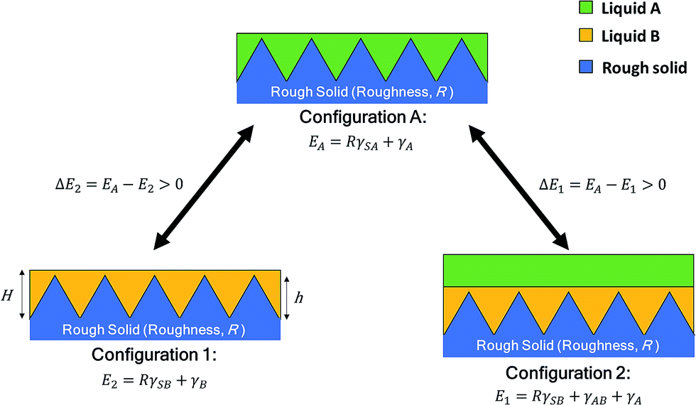 | ||
| Fig. 2 Conditions required to achieve stable SLIPS. E1, E2, EA are the total free energy of configuration 1, 2, A, respectively. R is the roughness of rough surface. γA (γB) is the vapor/liquid A (B) interfacial tension. γSA (γSB) is the solid/liquid A (B) interfacial tension. | ||
The total free energy of configuration A must be larger than that of configurations 1 and 2. The binding conditions for SLIPS stability are:
(1) The liquid covering the solid must completely contact the solid.
(2) The thickness of the lubricant layer must be sufficient to negate the influence of capillary forces.
(3) The surface roughness distribution indicated no defects in the film.
(4) Liquids A and B must be immiscible.
The condition that the energy of configuration A is larger than that of configuration 1 is shown as:
| ΔE1 = EA − E1 > 0 | (1) |
| R(γSA − γSB) − γAB > 0 | (2) |
Substituting eqn (2) into eqn (3) and arranging yields:
| R(γBcosθB − γAcosθA) − γAB > 0 | (3) |
 | (4) |
The condition that the energy of configuration A is larger than that of configuration 2 is shown as:
| ΔE2 = EA − E2 > 0 | (5) |
| R(γSA − γSB) + γA − γB > 0 | (6) |
Substituting eqn (5) into eqn (6) and arranging yields:
| R(γBcosθB − γAcosθA) + γA − γB > 0 | (7) |
The stability of SLIPS can therefore be calculated from eqn (3) and (7). EA is the sum of the surface energy of the droplets and the under layer. E1 is the sum of the surface energy of the droplets, lubricant and under layer. E2 is the sum of the surface energy of the lubricant and under layer. The droplet penetrates into the lubricant oil when eqn (1) or (2) is not satisfied. Eqn (1) and (2) show that SLIPS require a low surface energy under layer. Thus, a rough under layer of low surface energy was prepared by electrospinning low surface energy materials of PVDF–HFP in this study.
Laser microscope images of the surface structure with increasing electrospinning time are shown in Fig. 3(a). Increasing electrospinning time resulted in less exposed glass substrate, as indicated by the decreasing blue color in the three-dimensional laser micro images. PVDF–HFP nanofibers preferentially adhered to the glass, because of the interaction between the charged polymers and charged under layer. Electrospun polymers which are typically poor conductivity continue holding on to the charges immediately after deposition.31 Thus, the density of the PVDF–HFP under layer could be controlled by the electrospinning time. The Rrms of the surface structure at each electrospinning time is shown in Fig. 3(b). The PVDF–HFP under layer greatly increased the surface roughness, compared with the glass substrate. The Rrms value exhibited a maximum after 5 min of electrospinning, after which it decreased, because macroscale parts of the uncoated substrate became filled. The contact angle changed little with electrospinning time. The water contact angles on the nanofiber PVDF–HFP under layer are shown in Fig. 3(c). The surface became hydrophobic upon coating with the nanofiber PVDF–HFP under layer. The contact angle increased with electrospinning time, and became constant after approximately 7 min. Surface roughness was at a maximum after 5 min of electrospinning, but the contact angle was low because part of the glass surface remained exposed. The surface roughness and contact angle did not significantly change with electrospinning time, in contrast to the density of the PVDF–HFP under layer. Thus, electrospinning could be used to vary the structure of the under layer, without changing the surface energy.
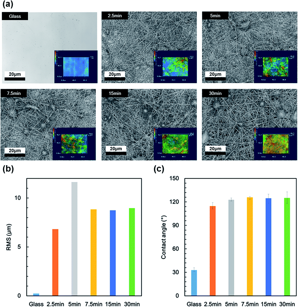 | ||
| Fig. 3 (a) Three-dimensional microscope images, (b) RMS surface roughness values, and (c) water contact angles of a PVDF under layer after electrospinning times of 0, 2.5, 5, 7.5, 15, and 30 min. | ||
Photographic images of the SLIPS before and after infusing with lubricant oil are shown in Fig. 4(a). The surface of the PVDF–HFP under layer before infusing appeared milky white, because of scattering reflection due to its high roughness. After infusing, the surface of the PVDF–HFP under layer appeared fogged, indicating that the lubricant oil suppressed scattering reflection, but retained light scattering. An SEM image and EDX map of the SLIPS before and after infusing are shown in Fig. 4(b). The lubricant smoothed the rough surface, by filling space between the fibers. Fig. 4(c) shows models depicting how the lubricant suppressed reflection. Reflected light consists of scattered and speculum components. The rough surface typically exhibited high scattering, because scattering depends on roughness. After infusing, the PVDF under layer exhibited low scattering because of it was smoother.
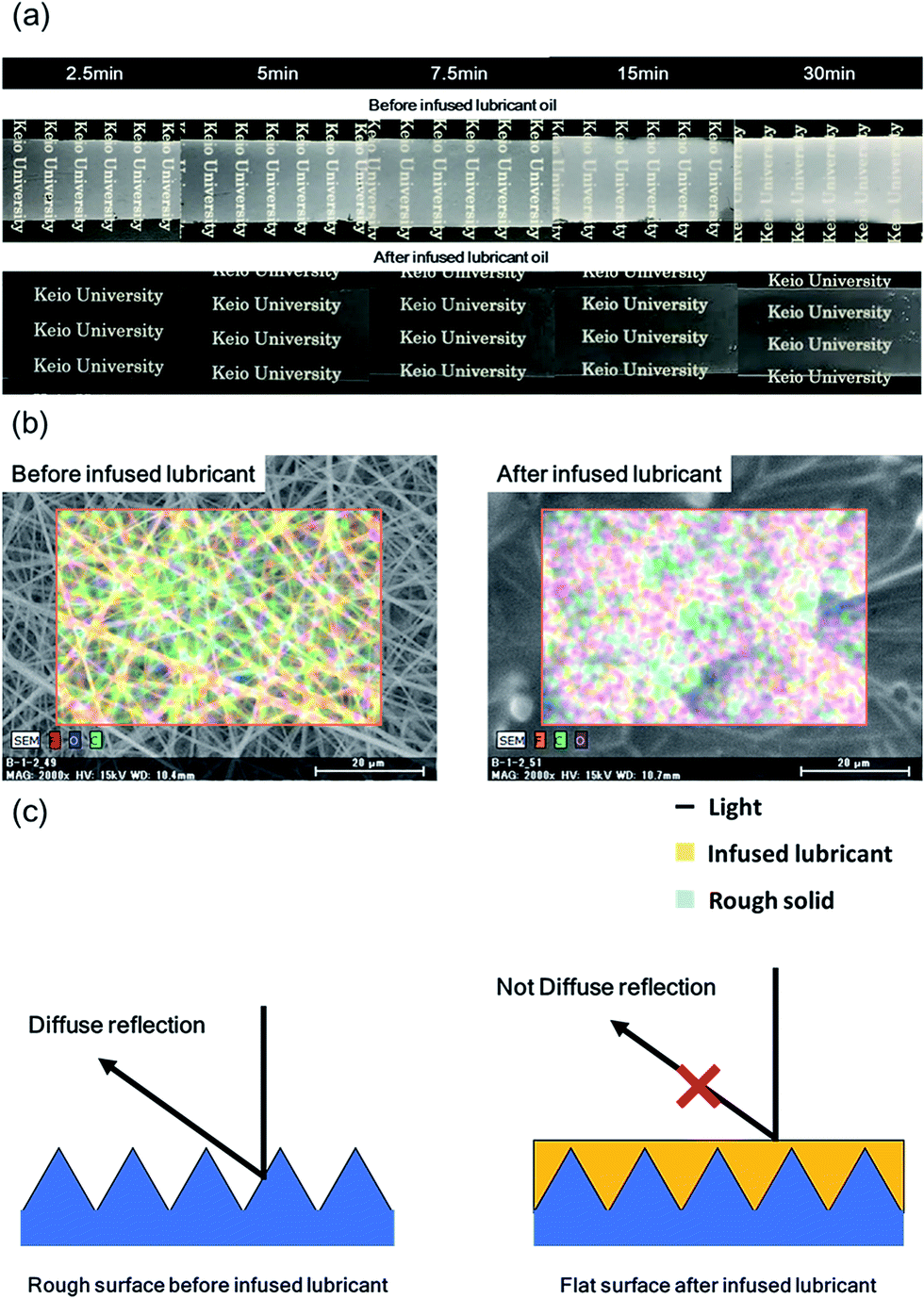 | ||
| Fig. 4 (a) Photographs of the nanofiber SLIPS before and after infusing with lubricant, for various electrospinning times. (b) SEM images and EDX maps of a PVDF under layer before and after infusing, for an electrospinning time of 30 min. (c) Models showing how lubricant suppresses reflection. | ||
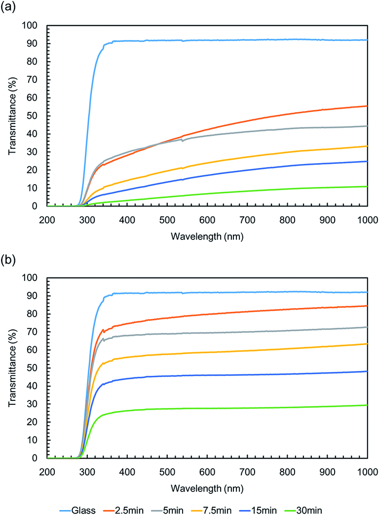
UV-vis absorption spectra of the SLIPS before infusing with lubricant are shown in Fig. 5(a). The transmittance of the PVDF–HFP under layer decreased at all wavelengths with increasing electrospinning time. The transmittance was higher at longer wavelengths, because of the wavelength dependence of reflectance. The UV-vis absorption spectra of the SLIPS after infusing with lubricant are shown in Fig. 5(b). The transmittance of the PVDF–HFP under layer increased at all wavelengths, after infusing with lubricant. This was caused by the lubricant suppressing reflection at all wavelengths. Thus, the wavelength dependence of the transmittance loss decreased after infusing. The HAZE of the PVDF–HFP under layer before infusing is shown in Fig. 6(a).
 | ||
| Fig. 5 UV-vis absorption spectra of nanofiber SLIPS (a) before and (b) after infusing with lubricant, for various electrospinning times. | ||
 | ||
| Fig. 6 Optical properties of SLIPS before (a) and (b) after infusing, for various electrospinning times. | ||
The T.T. of the PVDF–HFP under layer before infusing gradually decreased with increasing electrospinning time, which was consistent with increasing reflection or back scattering. The T.T. of the PVDF–HFP under layer after infusing was largely constant with increasing electrospinning time, as shown in Fig. 6(b), because the lubricant suppressed reflection. These results showed that the surface of the PVDF–HFP under layer after infusing was smooth after all electrospinning times. Some of the loss due to reflection was converted to scattering by the infused lubricant. Scattering of the PVDF–HFP under layer after infusing gradually increased with increasing electrospinning time, as represented by:
 | (8) |
The sliding angle of the PVDF–HFP under layer before and after infusing is shown in Fig. 7. Low sliding angles (≤10°) for water and hexadecane were observed after all electrospinning times. Hexadecane has a much lower surface energy (27 mN m−1) than the majority of solvents. The nanofiber SLIPS could therefore potentially slide a variety of liquids. The nanofiber SILPS was applied in a solar cell. Fig. 8 shows the I–V curve of the resulting cell. The decrease in power generation efficiency of a cell covered with a nanofiber SLIPS compared with another absent of any nanofiber SLIPS was 0.22%. This efficiency decrease is lower than that of conventional SLIPS, and resulted from the constant T.T. and enhanced scattering. Thus, the nanofiber Gel-SILPS is useful in optical devices such as solar cells, because this efficiency decrease is much lower than that due to fouling (Table 1).
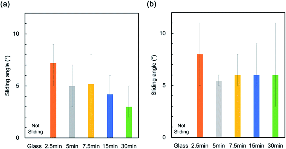 | ||
| Fig. 7 Sliding angles of 20 μL (a) water and (b) hexadecane droplets on nanofiber SLIPS. | ||
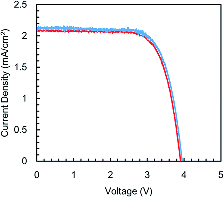 | ||
| Fig. 8 Photocurrent density (JSC) versus voltage (VOC) of a bare solar cell covered with a glass and nanofiber SLIPS. | ||
| V OC [V] | J SC [mA cm−2] | FF | Efficiency [%] | |
|---|---|---|---|---|
| Glass | 3.96 | 2.13 | 0.721 | 6.10 |
| Electrospun nanofiber SLIPS | 3.92 | 2.09 | 0.719 | 5.88 |
4. Conclusions
SLIPS exhibiting controlled scattering were prepared by electrospinning. The change in under layer structure with increasing electrospinning time was responsible for this. Reported antifouling coatings tend to lack both favourable antifouling and optical properties. High total transmittance (93.2%) and scattering properties were achieved by electrospinning, while maintaining the antifouling properties (hexadecane sliding angel of ≤10°). Such antifouling coating with high T.T. and scattering characteristics are useful in devices such as solar cells.Acknowledgements
We are grateful to Shiratori Laboratory Members and Yuka Abe.Notes and references
- T. Sarver, A. Al-Qaraghuli and L. L. Kazmerski, Renewable Sustainable Energy Rev., 2013, 22, 698–733 CrossRef.
- A. Sayyah, M. N. Horenstein and M. K. Mazumder, Sol. Energy, 2014, 107, 576–604 CrossRef.
- A. a. Kazem, M. T. Chaichan and H. a. Kazem, Renewable Sustainable Energy Rev., 2014, 37, 734–749 CrossRef.
- S. a M. Said and H. M. Walwil, Sol. Energy, 2014, 107, 328–337 CrossRef.
- W. Barthlott and C. Neinhuis, Planta, 1997, 202, 1–8 CrossRef CAS.
- K. Sunada, Y. Kikuchi, K. Hashimoto and A. Fujishima, Environ. Sci. Technol., 1998, 32, 726–728 CrossRef CAS.
- J. C. Yu, W. Ho, J. Yu, H. Yip, K. W. Po and J. Zhao, Environ. Sci. Technol., 2005, 39, 1175–1179 CrossRef CAS PubMed.
- O. Akhavan and E. Ghaderi, 2009, 20214–20220.
- T.-S. Wong, S. H. Kang, S. K. Y. Tang, E. J. Smythe, B. D. Hatton, A. Grinthal and J. Aizenberg, Nature, 2011, 477, 443–447 CrossRef CAS PubMed.
- a. K. Epstein, T.-S. Wong, R. a. Belisle, E. M. Boggs and J. Aizenberg, Proc. Natl. Acad. Sci. U. S. A., 2012, 109, 13182–13187 CrossRef CAS PubMed.
- B. Pokroy, A. K. Epstein, M. C. M. Persson-Gulda and J. Aizenberg, Adv. Mater., 2009, 21, 463–469 CrossRef CAS.
- H. a. Stone, ACS Nano, 2012, 6, 6536–6540 CrossRef CAS PubMed.
- I. Okada and S. Shiratori, ACS Appl. Mater. Interfaces, 2014, 6, 1502–1508 CAS.
- a. M. Stephan, Eur. Polym. J., 2006, 42, 21–42 CrossRef.
- H. Susanto and M. Ulbricht, J. Membr. Sci., 2009, 327, 125–135 CrossRef CAS.
- D. Djian, F. Alloin, S. Martinet and H. Lignier, J. Power Sources, 2009, 187, 575–580 CrossRef CAS.
- J. H. Cao, B. K. Zhu, G. L. Ji and Y. Y. Xu, J. Membr. Sci., 2005, 266, 102–109 CrossRef CAS.
- V. A. Ganesh, a. S. Nair, H. K. Raut, T. T. Yuan Tan, C. He, S. Ramakrishna and J. Xu, J. Mater. Chem., 2012, 22, 18479 RSC.
- M. Ma, R. M. Hill, J. L. Lowery, S. V Fridrikh and G. C. Rutledge, Macromolecules, 2005, 5549–5554 CAS.
- B. S. Lalia, S. Anand, K. K. Varanasi and R. Hashaikeh, Langmuir, 2013, 29, 13081–13088 CrossRef CAS PubMed.
- L. Wang, Y. Yu, P. C. Chen, D. W. Zhang and C. H. Chen, J. Power Sources, 2008, 183, 717–723 CrossRef CAS.
- H. Wu, L. Hu, M. W. Rowell, D. Kong, J. J. Cha, J. R. McDonough, J. Zhu, Y. Yang, M. D. McGehee and Y. Cui, Nano Lett., 2010, 10, 4242–4248 CrossRef CAS PubMed.
- L. Mai, L. Xu, C. Han, X. Xu, Y. Luo, S. Zhao and Y. Zhao, Nano Lett., 2010, 10, 4750–4755 CrossRef CAS PubMed.
- M. Y. Song, D. K. Kim, K. J. Ihn, S. M. Jo and D. Y. Kim, Nanotechnology, 2004, 15, 1861–1865 CrossRef CAS.
- K. Onozuka, B. Ding, Y. Tsuge, T. Naka, M. Yamazaki, S. Sugi, S. Ohno, M. Yoshikawa and S. Shiratori, Nanotechnology, 2006, 17, 1026–1031 CrossRef CAS PubMed.
- W. J. Li, C. T. Laurencin, E. J. Caterson, R. S. Tuan and F. K. Ko, J. Biomed. Mater. Res., 2002, 60, 613–621 CrossRef CAS PubMed.
- H. Yoshimoto, Y. M. Shin, H. Terai and J. P. Vacanti, Biomaterials, 2003, 24, 2077–2082 CrossRef CAS PubMed.
- F. Yang, R. Murugan, S. Wang and S. Ramakrishna, Biomaterials, 2005, 26, 2603–2610 CrossRef CAS PubMed.
- K. Yoon, K. Kim, X. Wang, D. Fang, B. S. Hsiao and B. Chu, Polymer, 2006, 47, 2434–2441 CrossRef CAS.
- R. Gopal, S. Kaur, C. Y. Feng, C. Chan, S. Ramakrishna, S. Tabe and T. Matsuura, J. Membr. Sci., 2007, 289, 210–219 CrossRef CAS.
- H. Schreuder-Gibson, P. Gibson and P. Tsai, Int. Nonwovens J., 2004, 39–45 CAS.
Footnote |
| † Electronic supplementary information (ESI) available. See DOI: 10.1039/c6ra00276e |
| This journal is © The Royal Society of Chemistry 2016 |