Thoroughly mesoporous TiO2 nanotubes prepared by a foaming agent-assisted electrospun template for photocatalytic applications

Y. Lv a, Z. L. Xub, H. Asaia, N. Shimadaa and K. Nakane*a
aFrontier Fiber Technology and Science, Graduate School of Engineering, University of Fukui, 3-9-1, Bunkyo, Fukui, 910-8507, Japan. E-mail: nakane@u-fukui.ac.jp
bHeadquarters for Innovative Society-Academic Cooperation, University of Fukui, Bunkyo 3-9-1, Fukui, 910-8507, Japan

Received 5th January 2016 , Accepted 15th February 2016

First published on 16th February 2016


Abstract

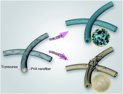
A thoroughly mesoporous long TiO2 nanotube with intact morphology was firstly prepared using a foaming agent-assisted electrospun template method in which an electrospun water-soluble PVA nanofiber was used as the template. The large volumes of vapors released from the introduced foaming agents are attributed to the production of mesopores with uniform spatial distribution on the whole TiO2 tube wall and these mesopores prevent damage to the TiO2 nanotubular morphology during the PVA template removal. The present work represents a critically important solution in advancing the electrospinning technique for generating mesoporous nanotubes in an effective and facile manner.

Mesoporous materials have attracted more and more interest owing to their high specific surface areas compared to their conventional solid counterparts. They can interact with atoms, ions, molecules, and nanoparticles not only at their surfaces but also throughout the bulk of the material.1 Among the families that have experienced intensive advances, mesoporous TiO2 nanotubes are of particular interest and are undergoing the most explosive growth mainly due to the perspective of using the structures to enhance the properties in Grätzel-type solar cells2 and photocatalytic materials3 compared to TiO2 with other morphologies (e.g. nanoparticles and nanofibers). Therefore, the design and synthesis of mesoporous TiO2 nanotubes with uniform spatial distribution are important from both fundamental and technological viewpoints. Up to date, several methods have been developed to fabricate mesoporous TiO2 nanotubes, such as hydrothermal route,4 template assisted process,5 and electrospinning technique6 and so on. However, among these methods, it still remains a great challenge to fabricate thoroughly mesoporous nanotubes with satisfied intact geometry in a simple and fast manner.7

Electrospinning is a versatile, simple, and cost-effective strategy for producing 1D nanostructures of a wide range of polymers with tunable diameters and morphologies.8 These uniform nanofibers can be used as the ideal templates for preparing tubular materials. However, the electrospun template-directed approach only works best for relatively short structures because of the overlapping or entanglement between long, flexible nanofibers templates inevitably causes interconnections between resultant composite nanofibers. These interconnections generally became very weak points leading to the damage of the resultant tubular morphology after the post treatment (e.g. the template removal). Thus the as-fabricated nanotubes from most of the reported works still can not overcome the following limitations such as solid surface without pores, damage of tubular morphology during the post treatment of templates and complicated preparation steps.7

How to advance the facile electrospinning method to create mesoporous nanotubes with intact morphology through a facile manner in a breakthrough is still a challenging issue. With the primary motivation, for the first time, we present a facile strategy, namely, foaming agent assisted electrospun template method for preparing long mesoporous TiO2 nanotubes. The resultant mesoporous nanotubes exhibit much better morphology without the damage of tubular structure and better performance compared to the conventional solid nanotubes and the commercially available P25 product, suggesting their very promising application prospect. The present work might open new doors for the exploration of mesoporous nanotubes with high photoelectrochemical property.

Mesoporous TiO2 nanotubes were prepared by the following steps. Water-soluble PVA nanofibers were firstly electrospun for the template by dissolving PVA in distilled water. As-spun PVA nanofibers were then immersed in ethanol solution containing titanium isopropoxide (TTIP) and foaming agent diisopropyl azodiformate (DIPA) for 30 minutes. After that the composite nanofibers were taken out and dried under room temperature for 20 min. Finally the composite nanofibers were calcined at 500 °C for 2 h to obtain the mesoporous TiO2 nanotubes. For comparison, the controlled solid TiO2 nanotubes were obtained the same as the above processes without adding DIPA. The resultant mesoporous TiO2 and solid TiO2 nanotubes were marked as sample NT1 and sample NT2, respectively. The detailed experimental section can be seen in ESI.

Scanning electron microscopy (SEM) is used to characterize the electrospun precursor nanofibers and nanotubes obtained by subsequent calcination. The as-spun PVA nanofiber template of sample NT1 has smooth surface with average diameter of 300 nm and lengths up to several hundred of micrometres (Fig. S1a). After immersed in DIPA/TTIP ethanol solution, the composite nanofiber diameter increased to 450 nm (Fig. S1b) owing to the uniform coating of TiO2 precursor on PVA nanofibers surface.9 The corresponding elemental mappings show uniform spatial distribution of Ti, O, and N (Fig. S2), indicating DIPA molecules uniformly distributed at the whole tube wall. Fig. 1a shows the typical SEM image of the sample NT1 obtained from DIPA/Ti-precursor/PVA nanofibers by calcination. Surprisingly, the nanotubes remained intact after PVA template removal, almost without damage to the tubular morphology. With clear observation, Fig. 1b shows a representative cross-section SEM image of the mesoporous TiO2 nanotubes, showing that the tube wall possesses a thoroughly and uniformly porous structure.


image file: c6ra00241b-f1.tif
Fig. 1 Typical SEM images of (a and b) the mesoporous TiO2 nanotubes and (c and d) the solid TiO2 nanotubes under different magnifications. (e) A representative TEM image of a single mesoporous TiO2 nanotube. The inset is the corresponding SAED pattern recorded from the nanotube wall. (f) XRD patterns of sample NT1 and sample NT2 after calcination.

For comparison, Fig. 1c shows the SEM image of the sample NT2 obtained from the control experiment without adding foaming agent in the initial solution. Compared to sample NT1, sample NT2 emerged large cracks at tube wall and collapses of the tube skeleton. High resolution SEM image (Fig. 1d) of the sample NT2 exhibits a solid and fragile tube wall with many crevices (marked by red arrow), which are quite different from the mesoporous structures synthesized with the 10 wt% foaming agent, suggesting that the added foaming agent plays a critical role in the formation of the mesoporous structures at tube wall and maintaining the tubular morphology.

For further characterization to the above two nanotubes with different surface structure, Fig. 1e (also Fig. S3a) provides a representative TEM image of a single sample NT1, clearly indicating the formation of tubular structure with an average inner diameter and wall thickness of 300 nm and 70 nm, respectively, which are quite consistent with the results from SEM observation. Meanwhile, this image further confirms that densely distributed pores exist throughout the tube wall. The SAED pattern (the inset in Fig. 1e) recorded at the whole tube wall suggests that the obtained product is anatase TiO2 (JCPDS, no. 21-1272) with a polycrystalline structure. While the TME image of the sample NT2 shows a nanotubular structure with solid surface (Fig. S3), which well agrees with the result from SEM analysis. Furthermore, the EDS spectrum discloses that the tube wall of sample NT1 mainly possess Ti and O (Fig. S4). Element N that belongs to DIPA foaming agent was not detected in the calcined samples, suggesting all the precursor nanofibers have been completely converted into mesoporous TiO2 nanotubes with a high purity. It is necessary to note that almost long mesoporous nanotube survived the scratching and ultrasonic treatments during the TEM sample preparation process, indicating their high structural robustness. As confirmed by X-ray diffraction studies (Fig. 1f), the nanotube walls of both sample NT1 and sample NT2 were made of polycrystalline anatase TiO2 (JCPDS, no. 21-1272), suggesting the pure phase of both resultant nanotubes and also implying that the foaming agent has no effect on the change of crystalline and compositions of the resultant products. The sharp diffraction peaks indicate that both the products are highly crystalline.

Based on the effect of foaming agent of DIPA on the tubular framework and tubular structure of the resultant products, nitrogen adsorption isotherms were used to calculate the specific surface area and pore size distribution of these two different nanotubes, which are critical factors for affecting the chemical and physical performances for materials.10 Fig. 2a revealed that the sample NT1 exhibits the type IV isotherm behaviour with H3 hysteresis, implying that the as-obtained nanotubes are mesoporous with a Brunauer–Emmett–Teller (BET) surface area of 89 m2 g−1. And its main pore size was found to be 16 nm from the Barrett–Joyner–Halenda (BJH) pore size distribution. However, the calcined sample NT2 without adding DIPA shows only a BET surface area of ca. 17 m2 g−1 (Fig. 2a), which is about 5 times lower than that of sample NT1. Moreover, sample NT1 (0.23 cm3 g−1) possesses much larger pore volume than NT2 (0.064 cm3 g−1), implying that the foaming agent of DIPA is responsible for the formation of the mesopores within the nanotube wall. This comparison clearly and unambiguously suggests the foaming agent plays a critically important role on the formation of the mesoporous nanotubes, which helps create the pores throughout the entire tube wall with uniform spatial distribution, leading to larger BET surface area of the resultant nanotubes. Meanwhile, the mesopores induced by foaming agent DIPA provide nanotube wall good air permeability and thus prevent the morphology of the resultant products from damage or collapses during the post treatment.


image file: c6ra00241b-f2.tif
Fig. 2 (a) Nitrogen adsorption–desorption isotherm (−196 °C) of the sample NT1 and sample NT2. (b) Corresponding pore size distribution.

The effect of adding DIPA or not on the formation of the as-prepared nanotubes with different morphology could be explained in Fig. 3a. First, the DIPA, the foaming agent, is assembled into the TiO2 precursor solutions when the DIPA is dissolved in the solutions. The DIPA is distributed homogeneously within the TiO2 precursor coating evidenced by elemental mapping observation and the formation of uniform porous structure throughout the tube wall. During the calcination process under air at 500 °C, the DIPA foamer, with the chemical formula of C8H14N2O4, is completely decomposed into vapor phases (e.g., CO2, NO2, and H2O), which cause the formation of the pores throughout the tube wall. The first formed mesopores on the tube wall thus provides the ventilation passage way for the large amount of released vapors from the subsequent decomposition of PVA template, which largely avoid the sudden and intensive released vapors to dash against the tube wall and thus protects the tube wall from the damage. It is noticeable that the interconnections between two nanotubes which are regarded as the weakest parts still maintain intact during the removal of PVA templates due to the mesoporous structure on the tube wall. Moreover, the mesopores makes the separate nanotubes integrated, as shown in Fig. S5, which not only increase the density of active sites with high accessibility but also facilitate the diffusion of reactants and products. The thermal behavior of the as-spun PVA/TTIP/DIPA nanofibers was measured using TG-DTA analysis (Fig. 3b). The initial weight loss in the low temperature range (30–130 °C) is attributed to the residual solvent decomposition and volatilization. The 10% weight loss between 130 and 200 °C is caused by the decomposition of DIPA (DTA exothermic peak at ∼160 °C), which results in the formation of mesoporous nanotube wall. The 30% weight loss at the higher temperatures (240–480 °C) should be attributed to the decomposition of PVA (DTA endothermic peak at 420 °C). Finally, the DTA exothermic peak at 500 °C is attributed to the TiO2 crystallization. In contrast, there are only two exothermic peaks observed for sample NT2, which are related to PVA decomposition. We also notice that the main DTA endothermic of PVA template in sample NT1 is a little lower than that in sample NT2. We explain that the mesoporous structure on tube wall facilitates the thermal conduction from outside into inside leading to PVA decomposition earlier and more completely than the solid one. In the case without adding DIPA, the interconnections, the weakest parts, between the as-spun PVA/TTIP nanofibers were firstly impacted by the large amount of released vapors during the PVA removal. These interconnections became to crack and these cracks tended to largen and zipper-type tear to the both ends of nanotube with increase of calcination time. During this process, the cracks also increase along with the whole tube wall and finally caused the collapses of the nanotubular framework, and a remarkable decrease of surface area. This whole process in the case of no adding DIPA was evidenced in Fig. S6. These data suggest that the introduction of the DIPA foaming agents notably affects the thermal behaviors of as-spun nanofibers.


image file: c6ra00241b-f3.tif
Fig. 3 (a) Schematic illustration of the formation of sample NT1 and sample NT2. (b) TG/DTA spectra of polymeric precursor nanofibers of sample NT1 and NT2.

For best photocatalytic activity, a high surface area and anatase structure of TiO2 with high crystalline are required. The tubular architectures with mesopores on the tube wall enhance the specific surface area to harvest UV light and cause increased scattering that improves light absorption and thus benefits the photocatalysis. The high surface area can also increase the number of interactions between surface catalytic centers in a solar energy conversion system.11 Constructing such mesoporous TiO2 nanotubes with high surface area and high anatase purity is the aim of this communication. The adsorption curves of methylene blue under dark environment over sample NT1, sample NT2 and commercial P25 are displayed in Fig. 4a. The concentration of the methylene blue solution over the sample NT1 was lower than that over the sample NT2 and commercial P25 after dark adsorption for 30 min, suggesting that thoroughly mesoporous structure is ideal support to enhance the dark physical adsorption capacity of sample NT1. The increased adsorption capacity is favourable for the enrichment of target reactants from the bulk solution onto the surface of photocatalyst. These reactants then effectively react with the photogenerated active species (such as electrons, holes, hydroxyl radicals and superoxide radicals) on the surface of TiO2 nanotubes, thus contributing to the improved photoredox activity and the overall photocatalytic efficiency.12


image file: c6ra00241b-f4.tif
Fig. 4 (a) Comparison of dark adsorption behaviour of methylene blue. (b) Comparison of photocatalytic degradation rates of methylene blue. (c) Average reaction rate constants (min−1) for the photodegradation of methylene blue. (d) Results of reusability experiments for photocatalytic methylene blue degradation using sample NT1.

The photodegradation curves of methylene blue over sample NT1, sample NT2 and commercial P25 are further displayed in Fig. 4b. It shows that the photodegradation efficiency of MB solution under UV light follows the order of sample NT1 (mesoporous TiO2 nanotubes) > sample NT2 (solid TiO2 nanotubes) > P25. From the kinetic studies on the photocatalytic reactions over the products, their photocatalytic performances can be well illustrated using the equation ln(C0/C) = k (where k is the average rate constant, C and C0 are the concentrations of the real-time and initial MB solutions respectively) by a pseudo-first-order pattern. As shown in Fig. 4c, the corresponding average reaction rate constants (k) are calculated to be 0.0023, 0.0806, 0.0395, 0.0257 min−1 for blank MB, sample NT1, sample NT2 and P25, respectively, suggesting that the photocatalytic efficiency of the mesoporous TiO2 nanotubes is much higher than its conventional solid counterparts and P25. This could be due to the increased synergistic interaction between tubular and mesoporous tube wall. The photocatalytic reaction over the mesoporous TiO2 nanotube will occur not only on the surface of nanotube but also randomly into the entire nanotube through the creation of the foaming agent induced pores throughout the tube wall and then bring significant enhancement to the photocatalytic activity of TiO2.13 Because of the unique tubular structure for nanotubes, photogenerated electrons and holes could arrive at the surface more rapidly than nanoparticles, leading to a longer lifetime. This indicates the time related to combination process of electrons and holes is prolonged, and therefore the charge carriers are separated efficiently and enhance photocatalytic activity compared with P25 nanoparticles.14

To further investigate the reusability and stability, mesoporous TiO2 nanotubes were recovered and reused for photodegradation of MB under the similar conditions. As shown in Fig. 4d, the result shows that the as-prepared mesoporous TiO2 nanotubes are relatively stable although the photocatalytic activity has a little decrease after 5 cycles of the photocatalysis experiment. The decrease could be explained for two reasons. One reason may be due to residual adsorption of methylene blue during the recovery process and another reason maybe the amount loss of the catalyst during the centrifugal separation. Fig. S7 shows the typical SEM image of sample NT1 (mesoporous TiO2 nanotubes) after photocatalysis. The result demonstrates that the photocatalysts maintain their initial structures in morphology with mesoporous nanotubes after degradation of methylene blue. Actually, their high structural robustness can also be evidenced by the ultrasonic treated sample during TEM measurement.

Thus, the higher photocatalytic activity of mesoporous TiO2 nanotubes could be associated with the presence of mesopores within the tube wall and interconnected nanotubes induced by the foaming agent. Recently, porous photocatalysts have been extensively attracted due to the superior advantages such as high surface-to-volume ratio and uniform pore size distribution. In this study, the mesoporous TiO2 nanotubes with thoroughly mesopores in the whole tube wall not only effectively enhance the surface area but also increase the number of interactions between surface catalytic centers in a solar energy conversion system. The thoroughly mesopores in the tube wall provide a direct charge carrier transport pathway in both the pores and tubes, thus optimizing charge collection efficiency11 which can efficiently adsorb dye molecules and allow the effective transportation of gaseous products.15 Furthermore, the fact that mesoporous TiO2 nanotubes exhibit better photocatalytic activity than solid counterpart could be also due to the more effective absorption of UV light and the increased rate of photogenerated electron–hole pairs on the surface.16 When the mesoporous TiO2 nanotubes are irradiated by light, some of the photons are not directly absorbed by the nanotubes, but they can be trapped within the mesopores and then repeatedly reflected until being totally absorbed. Thus, these synergetic effects as mentioned above are responsible for the much improved photocatalytic properties of the mesoporous TiO2 nanotubes with high activity and stability, which are potentially suitable for wastewater treatment and air purification applications.

Conclusions

We have successfully developed a facile strategy called the foaming agent assisted electrospun template to fabricate the mesoporous TiO2 nanotubes with intact morphology and high purity. The formation of numerous mesopores within the interconnected nanotube wall caused by removal of the introducing foaming agent DIPA remarkably enhance specific surface areas and effectively prevent TiO2 nanotubular morphology from damage during the PVA template removal. The as-prepared mesoporous TiO2 nanotubes exhibit a much higher photocatalytic activity than both the conventional solid counterparts and the commercially available P25 and also show relatively stable after 5 cycle of the photocatalysis experiment. The present work might open new doors for the exploration of mesoporous nanotubes for high performances in photovoltaic, lithium-ion insertion and catalytic applications.

References

  1. M. E. Davis, Nature, 2002, 417, 813 CrossRef CAS PubMed.
  2. B. O'Regan and M. Gratzel, Nature, 1991, 353, 737 CrossRef CAS; M. Gratzel, Nature, 2001, 414, 338 CrossRef PubMed.
  3. A. Fujishima and K. Honda, Nature, 1972, 238, 37 CrossRef CAS PubMed; J. Yu, G. Dai and B. J. Cheng, J. Phys. Chem. C, 2010, 114, 19378 Search PubMed; N. Liu, I. Paramasivam, M. Yang and P. J. Schmuki, Solid State Electrochem., 2012, 16, 3499 CrossRef; J. Zhao, X. Wang, T. Sun and L. J. Li, J. Alloys Compd., 2007, 434–435, 792 CrossRef; H.-J. Oh, J.-H. Lee, Y.-J. Kim, S.-J. Suh, J.-H. Lee and C.-S. Chi, Appl. Catal., B, 2008, 84, 142 CrossRef; R. Mohammadpour, A. Irajizad, M. M. Ahadian, N. Taghavinia and A. Dolati, Eur. Phys. J.: Appl. Phys., 2009, 47, 10601 CrossRef.
  4. D. V. Bavykin, V. N. Parmon, A. A. Lapkina and F. C. Walshc, J. Mater. Chem., 2004, 14, 3370 RSC.
  5. Y. Wan and D. Y. Zhao, Chem. Rev., 2007, 107, 2821 CrossRef CAS PubMed; F. Schüth, Angew. Chem., Int. Ed., 2003, 42, 3604 CrossRef PubMed; Y. Wan, Y. F. Shi and D. Y. Zhao, Chem. Mater., 2008, 20, 932 CrossRef; H. F. Yang and D. Y. Zhao, J. Mater. Chem., 2005, 15, 1217 Search PubMed.
  6. D. Li, A. Babel, S. A. Jenekhe and Y. N. Xia, Adv. Mater., 2004, 16, 2062 CrossRef CAS.
  7. Z. Xing, A. M. Asiri, A. Y. Obaid, X. Sun and X. Ge, RSC Adv., 2014, 4, 9061 RSC; Y. Wan, P. Chang, Z. Yang, G. Xiong, P. Liu and H. Luo, J. Mater. Chem. B, 2015, 3, 5595 RSC; Z. Bian, J. Zhu, F. Cao, Y. Huo, Y. Lu and H. Li, Chem. Commun., 2010, 46, 8451 RSC.
  8. C. Huang, S. J. Soenen, J. Rejman, B. Lucas, K. Braeckmans, J. Demeester and S. C. De Smedt, Chem. Soc. Rev., 2011, 40, 2417 RSC; A. Greiner and J. Wendorff, Angew. Chem., Int. Ed., 2007, 46, 5670 CrossRef CAS PubMed; D. Crespy, K. Friedemann and A. M. Popa, Macromol. Rapid Commun., 2012, 33, 1978 CrossRef PubMed; M. Bognitzki, T. Frese, M. Steinhart, A. Greiner, J. H. Wendorff, A. Schaper and M. Hellwig, Polym. Eng. Sci., 2001, 41, 982 Search PubMed; A. J. Mieszawska, R. Jalilian, G. U. Sumanasekera and F. P. Zamborini, Small, 2007, 3, 722 CrossRef PubMed.
  9. K. Nakane, N. Shimada, T. Ogihara, N. Ogata and S. Yamaguchi, J. Mater. Sci., 2007, 42, 4031 CrossRef CAS.
  10. W. Dong, Y. Sun, C. W. Lee, W. Hua, X. Lu, Y. Shi, S. Zhang, J. Chen and D. Zhao, J. Am. Chem. Soc., 2007, 129, 13894 CrossRef CAS PubMed; R. Liu, Y. Ren, Y. Shi, F. Zhang, L. Zhang, B. Tu and D. Zhao, Chem. Mater., 2008, 20, 1140 CrossRef; C.-H. Huang, D. Gu, D. Zhao and R.-A. Dong, Chem. Mater., 2010, 22, 1760 CrossRef; W. Zhou, F. Sun, K. Pan, G. Tian, B. Jiang, Z. Ren, C. Tian and H. Fu, Adv. Funct. Mater., 2011, 21, 1922 CrossRef.
  11. S. Liu, Z. R. Tang, Y. Sun, J. C. Colmenares and Y. J. Xu, Chem. Soc. Rev., 2015, 44, 5053 RSC.
  12. N. Zhang, M. Q. Yang, S. Liu, Y. Sun and Y. J. Xu, Chem. Rev., 2015, 115, 10307 CrossRef CAS PubMed; C. Han, M. Q. Yang, B. Weng and Y. J. Xu, Phys. Chem. Chem. Phys., 2014, 16, 16891 RSC.
  13. K. Naito, T. Tachikawa, M. Fujitsuka and T. Majima, J. Am. Chem. Soc., 2009, 131, 934 CrossRef CAS PubMed.
  14. Y. Zhang, Z. R. Tang, X. Fu and Y. J. Xu, ACS Nano, 2010, 4, 7303 CrossRef CAS PubMed; Y. Yu, P. Zhang, L. Guo, Z. Chen, Q. Wu, Y. Ding, W. Zheng and Y. Cao, J. Phys. Chem. C, 2014, 118, 12727 Search PubMed.
  15. J. C. Yu, X. Wang and X. Fu, Chem. Mater., 2004, 16, 1523 CrossRef CAS; C. Guo, M. Ge, L. Liu, G. Gao, Y. Feng and Y. Wang, Environ. Sci. Technol., 2009, 44, 419 CrossRef PubMed; W. Zhou, W. Li, J. Wang, Y. Qu, Y. Yang, Y. Xie, K. Zhang, L. Wang, H. Fu and D. Zhao, J. Am. Chem. Soc., 2014, 136, 9280 CrossRef PubMed.
  16. Q. Zhang, X. J. Li, F. B. Li and J. Chang, J. Chem. Phys., 2004, 20, 507 CAS; K. Liu, Y. Hsueh, H. Chen and T. Perng, J. Mater. Chem. A, 2014, 2, 5387 Search PubMed.

Footnotes

Electronic supplementary information (ESI) available: Detailed descriptions of experimental procedures and figures. See DOI: 10.1039/c6ra00241b
Y. Lv and Z. L. Xu contributed equally.

This journal is © The Royal Society of Chemistry 2016
Click here to see how this site uses Cookies. View our privacy policy here.